Inventory

This chapter contains the following topics:

Viewing Inventory Information

Beginning with Cisco DCNM release 6.x, you can view the inventory and the performance for both SAN and LAN switches by using the global Scope pane. You can select LAN, SAN, or both to view the inventory information. You can also export and print the inventory information.

You can either Print this information or export to Microsoft Excel.


Note

You can use the Print icon to print the information that is displayed or you can also use the Export icon to export the information that is displayed to a Microsoft Excel spreadsheet. You can also choose the column that you want to display.

The Inventory menu includes the following submenus:

Viewing Inventory Information for Switches

To view the inventory information for switches from the Cisco DCNM Web UI, perform the following steps:

Procedure


Step 1

Choose Inventory > View > Switches.

The Switches window with a list of all the switches for a selected Scope is displayed.

Step 2

You can also view the following information.

  • Group column displays the switch group to which the switch belongs.

  • In the Device Name column, select a switch to display the Switch Dashboard.

  • IP Address column displays the IP address of the switch.

  • WWN/Chassis ID displays the Worldwide Name (WWN) if available or chassis ID.

  • Health displays the health situation of the switch.

    Note 

    To refresh and recalculate the latest health data for all the switches on Cisco DCNM, click the Recalculate Health button above the switches table.

  • Mode column displays the current mode of the switch. The switch can be in Normal, Maintenance, or Migration mode.

  • Status column displays the status of the switch.

  • # Ports column displays the number of ports.

  • Model column displays the model name of the switch.

  • Serial No. column displays the serial number of the switch.

  • Release column displays the switch version.

  • Up Time column displays the time period for which the switch is active.

  • Container Based ISSU Mode column indicates whether the Container Based ISSU Mode is enabled or not. The container-based ISSU can be enabled for Cisco Nexus 3000 and Cisco Nexus 9000 series switches. This is a one-time configuration on the device.

    Enhanced in-service software upgrade (ISSU)—Enables you to upgrade the device software while the switch continues to forward traffic, which reduces the downtime typically caused by software upgrades (similar to the regular ISSU, also known as a non-disruptive upgrade). However, with container-based ISSU, the software runs inside a separate Linux container (LXC) for the supervisor and line cards, and a third container is created as part of the ISSU procedure and is brought up as a standby supervisor.

    Container-based ISSUs are supported on Cisco Nexus 3164Q, 9200 series switches, 9332PQ, 9372PX, 9372TX, 9396PX, 9396TX, 93120TX, and 93128TX switches.

    For more information about the Cisco Nexus 3000 and 9000 switches, where the Container-based ISSU feature is supported, see the following URLs:

    Cisco Nexus 9000 Series NX-OS Software Upgrade and Downgrade Guide, Release 9.x

    Cisco Nexus 3000 Series NX-OS Software Upgrade and Downgrade Guide, Release 9.x

    Cisco NX-OS ISSU Support Matrix

Step 3

Click Health to access the Health score window for a device. The Health score window includes health score calculation and health trend. The Overview tab displays the overall health score. All the modules, switch ports and alarms are taken into consideration while calculating the health score. Hover over the graph under Health Trend for detailed information on specific dates. Hover over the info icon next to Alarms to display the number of Critical, Major, Minor, and Warning alarms that have been generated.

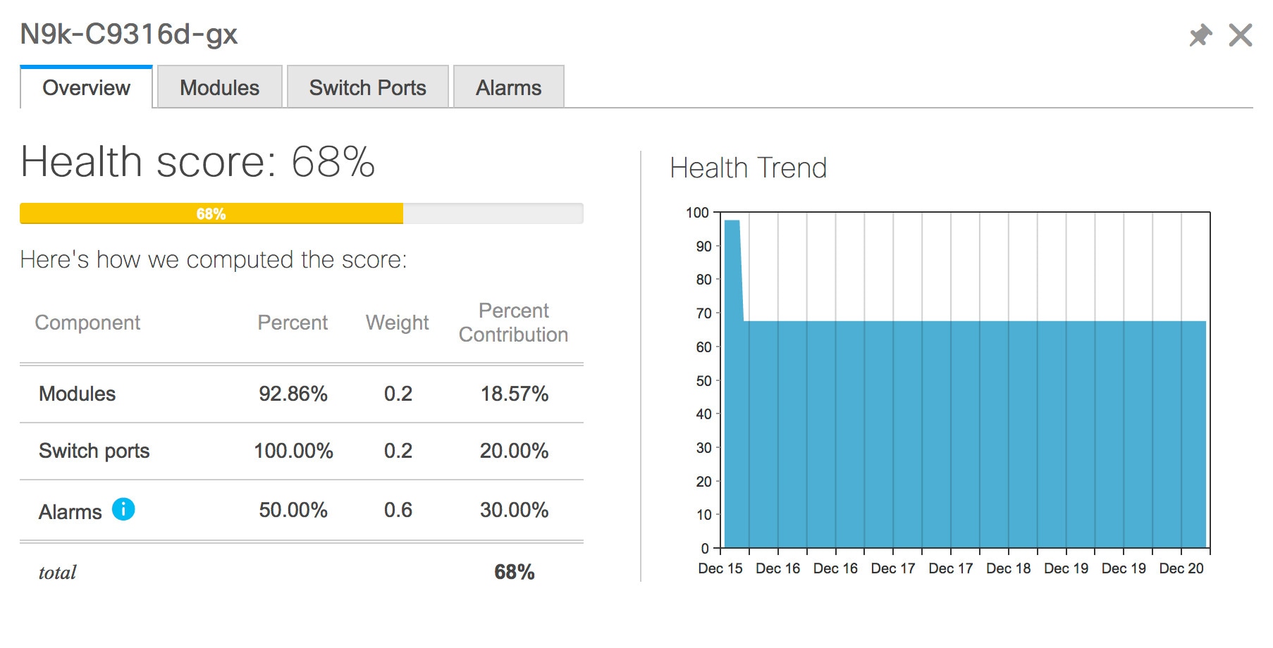
Click the Modules tab to display information about the various modules in the device. This tab displays information such as Name, Model name, Serial number, Status, Type, Slot, Hardware revision and Software revision.

Click the Switch Ports tab to display information about the device ports. This tab displays information such as Name, Description, Status, Speed, and the device to which a port is connected .

Click the Alarms tab to display information about the alarms that have been generated. This tab displays information such as alarm Severity, Message, Category, and the Policy that has been activated due to which the alarm is generated.

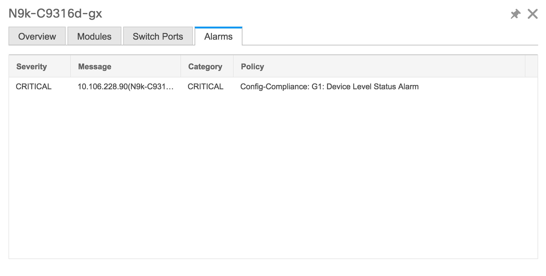
In the Health column, the switch health is calculated by the capacity manager based on the following parameters:

  • Total number of modules

  • Total number of modules impacted by the warning

  • Total number of switch ports

  • Total number of switch ports impacted by the warning

  • Total number of critical severity alarms

  • Total number of warning severity alarms

  • Total number of major severity alarms

  • Total number of minor severity alarms

Step 4

The value in the Health column is calculated based on the following:

  • Percentage of modules impacted by warnings (Contributes 20% of the total health).

  • Percentage of ports impacted by warnings (Contributes 20% of the total health).

  • Percentage of alarms (Contributes 60% of the total health). The critical alarms contribute the highest value to this percentage followed by major alarms, minor alarms and warning alarms.

You may also have your own health calculation formula by implementing the common interface class: com.cisco.dcbu.sm.common.rif.HealthCalculatorRif.

The default Java class is defined as: health.calculator=com.cisco.dcbu.sm.common.util.HealthCalculatorAlarms.

  • Capacity Manager calculates health only for the license switches. If the health column does not display a value, the switch either does not have a license or it has missed the capacity manager daily cycle.

  • If the switch is unlicensed, click Unlicensed in the DCNM License column. The Administration > License window appears which allows you to assign a license to the user.

  • The capacity manager runs two hours after the DCNM server starts. So, if you discover a device after two hours of the DCNM start time, the health will be calculated 24 hours after this DCNM start time

Starting from Cisco DCNM 11.3(1) Release, you can view information about switch health along with the switch summary by clicking on a switch in the Topology window or by choosing Control>Fabrics>Fabric Builder, selecting a fabric and clicking on a switch in the Fabric Builder window.


Viewing System Information

The switch dashboard displays the details of the selected switch.

Procedure

Step 1

From the Cisco DCNM home page, choose Inventory > View > Switches.

An inventory of all the switches that are discovered by Cisco DCNM Web UI is displayed.

Step 2

Click a switch in the Device Name column.

The Switch dashboard that corresponds to that switch is displayed along with the following information:

Step 3

Click the System Information tab. This tab displays detailed system information such as group name, health, module, time when system is up, serial number, the version number, contact, location, DCNM license, status, system log sending status, CPU and memory utilization, and VTEP IP address are displayed. Click Health to access the Health score screen, which includes health score calculation and health trend. The popup contains Overview, Modules, Switch Ports, and Events tabs.

  • (Optional) Click SSH to access the switch through Secure Shell (SSH).

  • (Optional) Click Device Manager to view a graphical representation of a Cisco MDS 9000 Family switch chassis, a Cisco Nexus 5000 Series switch chassis, a Cisco Nexus 7000 Series switch chassis, or a Cisco Nexus 9000 Series switch chassis including the installed switching modules, the supervisor modules, the status of each port within each module, the power supplies, and the fan assemblies.

  • (Optional) Click HTTP to access the switch through Hypertext Transfer Protocol (HTTP) for that switch.

  • (Optional) Click Accounting to go to the Viewing Accounting Information window pertaining to this switch.

  • (Optional) Click Backup to go to the Viewing a Configuration window.

  • (Optional) Click Events to go to the Viewing Events Registration window.

  • (Optional) Click Show Commands to display the device show commands. The Device Show Commands page helps you to view commands and execute them.

  • (Optional) Click Copy Running Config to Startup Config to copy the running configuration to the startup configuration.

  • Click Generate tac-pac to collect technical support from a device in Cisco DCNM. See the Collecting Technical Support from Devices section for more information.


Collecting Technical Support from Devices

You can choose the protocol while generating technical support from a device in Cisco DCNM Web Client. To collect technical support from a device in Cisco DCNM Web UI, perform the following steps:

Procedure

Step 1

Choose Inventory > View > Switches.

An inventory of all the switches that are discovered by Cisco DCNM is displayed.

Step 2

Click a switch in the Device Name column.

The switch dashboard that corresponds to that switch appears.

Step 3

In the Actions area, click Generate tac-pac.

The Generate tac-pac dialog box appears.

Step 4

Choose a management interface by clicking the appropriate radio button.

Valid values are default, vrf management, and vrf default. The default value selected is default.

Note 

This option is valid only for Nexus switches.

Step 5

Choose the transport protocol from switch to DCNM by clicking the appropriate radio button.

Valid values are TFTP, SCP, and SFTP.

Note 

If you choose the SCP or SFTP option, enter the DCNM server credentials.

Step 6

Click Ok.

After the tac-pac is generated and saved on server, a dialog box appears to open or save the file on your local machine.


Viewing Device Manager Information


Note

After you install Cisco DCNM for Windows, you must edit and provide credentials in the Cisco DCNM SAN Services to Log on. Navigate to Services > Cisco DCNM SAN Server > Cisco DCNM SAN Server Properties > Log On tab. Select This account radio button, and provide username and password. Click Ok. Log on to SSH and stop DCNM services. After you start the DCNM services, you must be able to use Device Manager.

Note

After you install Cisco DCNM for Linux, perform the procedure that is provided on the screen for Device Manager to be functional. Device Manager requires graphical environment that is configured properly in the Linux/OVA DCNM server.


The switch dashboard displays the details of the selected switch.

Procedure

Step 1

From the left menu bar, choose Inventory > View > Switches.

An inventory of switches discovered by Cisco DCNM Web Client is displayed.

Step 2

Click a switch in the Device Name column.

The Switch dashboard that corresponds to that switch is displayed along with the following information:

Step 3

Click the Device Manager tab. The Device Manager login dialog box appears. Log into the Device Manager application. The Device Manager provides a graphic representation of the installed switching modules, the supervisor modules, the status of each port within each module, the power supplies, and the fan assemblies.

For more information about the Device Manager, go to the following URL:

Cisco DCNM SAN Client Online Help


Installing a Switch License

To install a switch license from the Cisco DCNM Web UI, perform the following steps:
Procedure

Step 1

Choose Inventory > View > Switches.

Alternatively, you can choose Inventory > View > Switches.

Step 2

Click License in the switch dashboard.

Step 3

Click Install to install the switch license file on a switch.

A Switch License Install window appears.

Step 4

Click Select License File, and select the license file from your local system.

Step 5

Select the transport method. The available options are:

  • SCP

  • SFTP

Step 6

Enter the username and password to connect to the DCNM server.

Step 7

Click Install.


Rediscovering Switch Licenses

To rediscover switch licenses from the Cisco DCNM Web UI, perform the following steps:
Procedure

Step 1

Choose Inventory > View > Switches.

Alternatively, you can choose Inventory > View > Switches.

Step 2

Choose a switch in the Device Name column.

Step 3

Click the License tab in the switch dashboard.

Step 4

Click Rediscover to rediscover switch licenses on a switch.

Rediscovering the switch licenses takes some time.

Step 5

Click the Last Updated icon to refresh the licenses.


Interfaces

Displaying Interface Show Commands
To display interface show commands from the Cisco DCNM Web UI, perform the following steps:
Procedure

Step 1

Choose Inventory > View > Switches.

You see the Switches window displaying a list of all the switches for a selected Scope.
Step 2

In the Device Name column, select a switch to display Switch Dashboard.

Step 3

Click the Interfaces tab.

Step 4

Click Show to display the interface show commands.

The Interface Show Commands window helps you to view commands and execute them.


Rediscovering Interfaces
To rediscover interfaces from the Cisco DCNM Web UI, perform the following steps:
Procedure

Step 1

Choose Inventory > View > Switches.

The Switches window is displayed showing a list of all the switches for a selected Scope.

Step 2

In the Device Name column, select a switch to display Switch Dashboard.

Step 3

Click the Interfaces tab.

Step 4

Click Rediscover to rediscover the selected interfaces. For example, after you edit or enable an interface, you can rediscover the interface.


Viewing Interface History
To view the interface history from the Cisco DCNM Web UI, perform the following steps:
Procedure

Step 1

Choose Inventory > View > Switches.

You see the Switches window displaying a list of all the switches for a selected Scope.

Step 2

In the Device Name column, select a switch to display Switch Dashboard.

Step 3

Click the Interfaces tab.

Step 4

Click Interface History to display the interface history details such as Policy Name, Time of Execution, and so on.


VLAN

You create a VLAN by assigning a number to it; you can delete VLANs and move them from the active operational state to the suspended operational state.

To configure VLANs, choose Inventory > View > Switches, and then click a switch in the Device Name column.

The following table describes the buttons that appear on this page.

Table 1. VLAN Tab

Field

Description

Clear Selections

Allows you to unselect all the VLANs that you selected.

Add

Allows you to create Classical Ethernet or Fabric Path VLANs.

Edit

Allows you to edit a VLAN.

Delete

Allows you to delete a VLAN.

No Shutdown

Allows you to enable a VLAN.

Shutdown

Allows you to disable a VLAN.

Show

Allows you to display the VLAN show commands.

This section contains the following:

Adding a VLAN
To add a VLAN from the Cisco DCNM Web UI, perform the following steps:
Procedure

Step 1

Choose Inventory > View > Switches.

You see the Switches window displaying a list of all the switches for a selected Scope.

Step 2

In the Device Name column, select a switch to display the Switch Dashboard.

Step 3

Click the VLAN tab.

Step 4

Click Add to create Classical Ethernet or Fabric Path VLANs. In the Add VLAN window, specify the following fields:

  1. In the Vlan Id field, enter the VLAN ID.

  2. In the Mode field, specify whether you are adding Classical Ethernet or Fabric Path VLAN.

  3. Select the Admin State ON check box to specify whether the VLAN is shut down or not.


Editing a VLAN
To edit a VLAN from the Cisco DCNM Web UI, perform the following steps:
Procedure

Step 1

Choose Inventory > View > Switches.

The Switches window is displayed with a list of all the switches for a selected Scope.

Step 2

In the Device Name column, select a switch to display the Switch Dashboard.

Step 3

Select one or more VLANs, and then click the Edit.


Deleting a VLAN
To delete a VLAN from the Cisco DCNM Web UI, perform the following steps:
Procedure

Step 1

Choose Inventory > View > Switches.

You see the Switches window displaying a list of all the switches for a selected Scope.

Step 2

In the Device Name column, select a switch to display the Switch Dashboard.

Step 3

Click VLAN tab.

Step 4

Select the VLAN that you want to delete, and then click Delete.


Shutting Down a VLAN
To shut down a VLAN from the Cisco DCNM Web UI, perform the following steps:
Procedure

Step 1

Choose Inventory > View > Switches.

You see the Switches window displaying a list of all the switches for a selected Scope.

Step 2

In the Device Name column, select a switch to display Switch Dashboard.

Step 3

Click the VLAN tab.

Step 4

Click Shutdown to disable a VLAN.

To enable a VLAN, click No Shutdown button. For example, if you want to start traffic flow on a VLAN you can enable it.


Displaying VLAN Show Commands
To display VLAN show commands from the Cisco DCNM Web UI, perform the following steps:
Procedure

Step 1

Choose Inventory > View > Switches.

The Switches window is displayed, showing a list of all the switches for a selected Scope.

Step 2

In the Device Name column, select a switch to display Switch Dashboard.

Step 3

Click the VLAN tab.

Step 4

Click Show to display the VLAN show commands. Based on the VLAN selection, you can show the VLAN commands. Interface Show Commands window displays the commands and allows you to execute them.


FEX

The Fabric Extender feature allows you to manage a Cisco Nexus 2000 Series Fabric Extender and its association with the Cisco NX-OS switch that it is attached to. A Fabric Extender is connected to the switch through physical Ethernet interfaces or a Port Channel. By default, the switch does not allow the attached Fabric Extender to connect until it has been assigned a chassis ID and is associated with the connected interface. You can configure a Fabric Extender host interface port as a routed or Layer 3 port. However, no routing protocols can be tied to this routed interface.


Note

FEX feature is available on LAN devices only. Therefore, you will see FEX on Cisco DCNM Inventory Switches. If a Cisco Nexus Switch is discovered as part of SAN fabric, FEX feature is not available. FEX is also not supported on Cisco Nexus 1000V devices.

Note

4x10G breakout for FEX connectivity is not supported on Cisco Nexus 9500 Switches.


Note

The Fabric Extender may connect to the switch through several separate physical Ethernet interfaces or at most one port channel interface.


This section describes how to manage Fabric Extender (FEX) on Cisco Nexus Switches through Cisco DCNM.

You can create and manage FEX from Cisco DCNM Inventory > Switches.


Note

FEX tab is visible only if you choose a LAN device.


The following table describes the fields that appear on this page.

Table 2. FEX Operations

Field

Description

Add

Click to add a new FEX to a Cisco Nexus Switch.

Edit

Select any active FEX radio button and click Edit to edit the FEX configuration.

You can create an edit template and use it for editing FEX. Select template type as POLICY and sub type as FEX.

Delete

Select the FEX radio button, and click Delete icon to delete the FEX associated with the switch.

Show

Allows you to view various configuration details for the selected FEX ID. You can select the following from the drop-down list.

  • show_diagnostic

  • show_fex

  • show_fex_detail

  • show_fex_fabric

  • show_fex_inventory

  • show_fex_module

The variables for respective show commands are displayed in the Variables area. Review the Variables and click Execute. The output appears in the Output area.

You can create a show template for FEX. Select template type as SHOW and sub type as FEX.

FEX History

Allows you to view the history of the FEX configuration tasks for a particular FEX. You can review the Event Type, Policy Name, Status, Time of Execution, User Name for the selected FEX.

Table 3. FEX Field and Description

Field

Description

Fex Id

Uniquely identifies a Fabric Extender that is connected to a Cisco NX-OS device.

Fex Description

Description that is configured for the Fabric Extender.

Fex Version

Specifies the version of the FEX that is associated with the switch.

Pinning

An integer value that denotes the maximum pinning uplinks of the Fabric Extender that is active at a time.

State

Specifies the status of the FEX as associated with the Cisco Nexus Switch.

Model

Specifies the model of the FEX.

Serial No.

Specifies the configured serial number.

Note 

If this configured serial number and the serial number of the Fabric Extender are not the same, the Fabric Extender will not be active.

Port Channel

Specifies the port channel number to which the FEX is physically connected to the Switch.

Ethernet

Refers to the physical interfaces to which the FEX is connected.

vPC ID

Specifies the vPC ID configured for FEX.

This chapter includes the following sections:

Add FEX

To add single-home FEX from the Cisco DCNM Web UI, perform the following steps:

Before you begin

You can add a Fabric Extender (FEX) to the Cisco Nexus Switches through the Cisco DCNM Web Client. If the FEX is physically connected to the switch, FEX will become online after it is added. If the FEX is not physically connected to the switch, the configuration is deployed to the switch, which in turn enables FEX when connected.


Note

You can create only single homed FEX through Inventory > Switches > FEX > Add FEX. To create a dual-homed FEX, use the vPC wizard through Configure > Deploy > vPC.


Ensure that you have successfully discovered LAN devices and configured LAN credentials before you configure FEX.

Procedure

Step 1

Choose Inventory > Switches > FEX.

The FEX window is displayed.

Step 2

Click the Add FEX icon.

Step 3

In the General tab, in the PORTCHANNEL field, enter the interface port channel number which is connected to the FEX.

Step 4

In the INT_RANGE field, enter the interface range within which the FEX is connected to the switch.

Note 

Do not enter the interface range, if the interfaces are already a part of port channel.

Step 5

In the FEX_ID field, enter the ID for FEX that is connected to a Cisco NX-OS device.

The identifier must be an integer value between 100 to 199.

Step 6

Click Add.

The configured Single-home FEX appears in the list of FEXs associated to the device.


Edit FEX

To edit and deploy FEX from the Cisco DCNM Web UI, perform the following steps:

Procedure

Step 1

Choose Inventory > Switches > FEX.

The FEX window is displayed.

Step 2

Select the FEX radio button that you must edit. Click Edit FEX icon.

Step 3

In the Edit Configuration window, from the Policy drop-down list, select Edit_FEX to edit the FEX configuration.

Step 4

Edit the pinning and FEX_DESC fields, as required.

Note 

If you initially configured port 33 on the parent switch as your only fabric interface, all 48 host interfaces are pinned to this port. If you provision another port, for example 35, then you must perform this procedure to redistribute the host interfaces. All host interfaces are brought down and host interfaces 1 to 24 are pinned to fabric interface 33 and host interfaces 25 to 48 are pinned to fabric interface 35.

Step 5

Click Preview.

You can view the generated configuration for the selected FEX ID. The following is a configuration example for FEX ID 101.

fex 101
pinning max-links 1
description test
Step 6

After you review the configuration summary on the Preview window, on the Edit Configuration screen, click Deploy to deploy the FEX for the switch.


VDCs

This section describes how to manage Virtual Device Contexts (VDCs) on Cisco Nexus 7000 Switches through Cisco DCNM.

Users with the network administrator (network-admin) role can create Virtual Device Contexts (VDCs). VDC resource templates limit the amount of physical device resources available to the VDC. The Cisco NX-OS software provides a default resource template, or you can create resource templates.

You can create and manage VDCs from Cisco DCNM Inventory > Switches > VDCs. As Cisco DCNM supports DCNM on Cisco Nexus 7000 Series only, click an active Cisco Nexus 7000 Switch. After you create a VDC, you can change the interface allocation, VDC resource limits, and the high availability (HA) policies.

The following table describes the fields that appear on this page.

Table 4. VDC Operations

Field

Description

Add

Click to add a new VDC.

Edit

Select any active VDC radio button and click Edit to edit the VDC configuration.

Delete

Allows you to delete the VDC. Select any active VDC radio button and click Delete to remove the VDC associated with the device.

Resume

Allows you to resume a suspended VDC.

Suspend

Allows you to suspend an active non-default VDC.

Save the VDC running configuration to the startup configuration before suspending the VDC. Otherwise, you will lose the changes to the running configuration.

Note 

You cannot suspend the default VDC.

Caution 

Suspending a VDC disrupts all traffic on the VDC.

Rediscover

Allows you to resume a non-default VDC from the suspended state. The VDC resumes with the configuration that is saved in the startup configuration.

Show

Allows you to view the Interfaces and Resources that are allocated to the selected VDC.

In the Interface tab, you can view the mode, admin-status, and operational status for each interface associated with the VDC.

In the Resource tab, you can view the allocation of resources and current usage of these resources.

Table 5. Vdc Table Field and Description

Field

Description

Name

Displays the unique name for the VDC

Type

Species the type of VDC. The two types of VDCs are:

  • Ethernet

  • Storage

Status

Specifies the status of the VDC.

Resource Limit-Module Type

Displays the allocated resource limit and module type.

HA-Policy

  • Single Supervisor

  • Dual Supervisor

Specifies the action that the Cisco NX-OS software takes when an unrecoverable VDC fault occurs.

You can specify the HA policies for single supervisor module and dual supervisor module configurations when you create the VDC. The HA policy options are as follows:

Single supervisor module configuration:

  • Bringdown—Puts the VDC in the failed state. To recover from the failed state, you must reload the physical device.

  • Reload—Reloads the supervisor module.

  • Restart—Takes down the VDC processes and interfaces and restarts it using the startup configuration.

Dual supervisor module configuration:

  • Bringdown—Puts the VDC in the failed state. To recover from the failed state, you must reload the physical device.

  • Restart—Takes down the VDC processes and interfaces and restarts it using the startup configuration.

  • Switchover—Initiates a supervisor module switchover.

The default HA policies for a non-default VDC that you create is restart for a single supervisor module configuration and switchover for a dual supervisor module configuration. The default HA policy for the default VDC is reload for a single supervisor module configuration and switchover for a dual supervisor module configuration.

Mac Address

Specifies the default VDC management MAC address.

Management Interface

  • IP Address Prefix

  • Status

Species the IP Address of the VDC Management interface. The status shows if the interface if up or down.

SSH

Specifies the SSH status


Note

If you change the VDC hostname of a neighbor device after initial configuration, the link to the old VDC hostname is not replaced with the new hostname automatically. As a workaround, we recommend manually deleting the link to the old VDC hostname.


This chapter includes the following sections:

Add VDCs

To add VDC from the Cisco DCNM Web UI, perform the following steps:

Before you begin

Ensure that you have discovered the physical device using a username that has the network-admin role.

Obtain an IPv4 or IPv6 address for the management interface (mgmt 0) if you want to use out-of-band management for the VDC.

Create a storage VDC to run FCoE. The storage VDC cannot be the default VDC and you can have one storage VDC on the device.

Procedure

Step 1

Choose Inventory > Switches > VDC.

The VDC window is displayed.

Step 2

Click the Add VDC icon.

Step 3

From the drop-down list, select the VDC type.

You can configure the VDC in two modes.

The default VDC type is Ethernet.

Step 4

Click OK.


Configuring Ethernet VDCs

To configure VDC in Ethernet mode from the Cisco DCNM Web UI, perform the following steps:

Procedure

Step 1

In the General Parameter tab, specify the VDC Name, Single supervisor HA-policy, Dual supervisor HA-policy, and Resource Limit - Module Type.

Step 2

In the Allocate Interface tab, select the network interfaces (dedicated interfaces membership) to be allocated to the VDC.

Click Next.

Step 3

In the Allocate Resource tab, specify the resource limits for the VDC.

Select the radio button and choose Select a Template from existing Templates or Create a New Resource Template. VDC resource templates describe the minimum and maximum resources that the VDC can use. If you do not specify a VDC resource template when you create a VDC, the Cisco NX-OS software uses the default template, vdc-default.

  • If you choose Select a Template from existing Templates, from the Template Name drop-down list, you can select None, global-default, or vdc-default.

    The template resource limits are detailed in the following below:

    Table 6. Template Resource Limits

    Resource

    Minimum

    Maximum

    Global Default VDC Template Resource Limits

    Anycast Bundled

    IPv6 multicast route memory

    8

    8

    Route memory is in megabytes.

    IPv4 multicast route memory

    48

    48

    IPv6 unicast route memory

    32

    32

    IPv4 unicast route memory

    VDC Default Template Resource Limits

    Monitor session extended

    Monitor session mx exception

    Monitor SRC INBAND

    Port Channels

    Monitor DST ERSPAN

    SPAN Sessions

    VLAN

    Anycast Bundled

    IPv6 multicast route memory

    IPv4 multicast route memory

    IPv6 unicast route memory

    IPv4 unicast route memory

    VRF

  • If you choose Create New Resource Template, enter a unique Template Name. In the Resource Limits area, enter the minimum and maximum limits, as required for the resources.

You can edit individual resource limits for a single VDC through the Cisco DCNM Web Client > Inventory > Switches > VDC.

Click Next.

Step 4

In the Authenticate tab, you can allow the Admin to configure the password and also authenticate users using AAA Server Groups.

In the Admin User Area:

  • Check the Enable Password Strength Check checkbox, if necessary.

  • In the Password field, enter the admin user password.

  • In the Confirm Password field, reenter the admin user password.

  • In the Expiry Date field, click the down arrow and choose an expiry date for the admin user from the Expiry Date dialog box. You can also select Never radio button not to expire the password.

In the AAA Server Groups area:

  • In the Group Name field, enter an AAA server group name.

  • In the Servers field, enter one or more host server IPv4 or IPv6 addresses or names, which are separated by commas.

  • In the Type field, choose the type of server group from the drop-down list.

Click Next.

Step 5

In the Management Ip tab, enter IPv4 or IPv6 Address information.

Click Next.

Step 6

In the Summary tab, review the VDC configuration.

Click Previous to edit any parameters.

Click Deploy to configure VDC on the device.

Step 7

In the Deploy tab, the status of the VDC deployment is displayed.

A confirmation message appears. Click Know More to view the commands that are executed to deploy the VDC.

Click Finish to close the VDC configuration wizard and revert to view the list of VDCs configured on the device.


Configuring Storage VDCs

To configure VDCs in storage mode from the Cisco DCNM Web UI, perform the following steps:

Before you begin

Create a separate storage VDC when you run FCoE on the device. Only one of the VDCs can be a storage VDC, and the default VDC cannot be configured as a storage VDC.

You can configure shared interfaces that carry both Ethernet and Fibre Channel traffic. In this specific case, the same interface belongs to more than one VDC. The shared interface is allocated to both an Ethernet and a storage VDC.

Procedure

Step 1

In the General Parameter tab, specify the VDC Name, Single supervisor HA-policy, Dual supervisor HA-policy, and Resource Limit - Module Type.

Step 2

In the Allocate FCoE Vlan tab, select the available Ethernet Vdc from the drop-down list.

The existing Ethernet VLANs range is displayed. Select None not to choose any available Ethernet VDCs.

You can allocate specified FCoE VLANs to the storage VDC and specified interfaces.

Click Next.

Step 3

In the Allocate Interface tab, add the dedicated and shared interfaces to the FCoE VDC.

Note 

The dedicated interface carries only FCoE traffic and the shared interface carries both the Ethernet and the FCoE traffic.

You can configure shared interfaces that carry both Ethernet and Fibre Channel traffic. In this specific case, the same interface belongs to more than one VDC. FCoE VLAN and shared interface can be allocated from same Ethernet VDC.

Click Next.

Step 4

In the Authenticate tab, you can allow the Admin to configure the password and also authenticate users using AAA Server Groups.

In the Admin User Area:

  • Check the Enable Password Strength Check checkbox, if necessary.

  • In the Password field, enter the admin user password.

  • In the Confirm Password field, reenter the admin user password.

  • In the Expiry Date field, click the down arrow and choose an expiry date for the admin user from the Expiry Date dialog box. You can also select Never radio button not to expire the password.

In the AAA Server Groups area:

  • In the Group Name field, enter an AAA server group name.

  • In the Servers field, enter one or more host server IPv4 or IPv6 addresses or names, which are separated by commas.

  • In the Type field, choose the type of server group from the drop-down list.

Click Next.

Step 5

In the Management Ip tab, enter IPv4 or IPv6 Address information.

Click Next.

Step 6

In the Summary tab, review the VDC configuration.

Click Previous to edit any parameters.

Click Deploy to configure VDC on the device.

Step 7

In the Deploy tab, the status of the VDC deployment is displayed.

A confirmation message appears. Click Know More to view the commands that are executed to deploy the VDC.

Click Finish to close the VDC configuration wizard and revert to view the list of VDCs configured on the device.


Edit VDC

To edit VDC from the Cisco DCNM Web UI, perform the following steps:

Procedure

Step 1

Choose Inventory > Switches > VDC.

The VDC window is displayed.

Step 2

Select the VDC radio button that you must edit. Click the Edit VDC icon.

Step 3

Modify the parameters as required.

Step 4

After you review the configuration summary on the Summary tab, click Deploy the VDC with the new configuration.


Viewing Inventory Information for Modules

To view the inventory information for modules from the Cisco DCNM Web UI, perform the following steps:

Procedure


Step 1

Choose Inventory > View > Modules.

The Modules window is displayed with a list of all the switches and its details for a selected Scope.

Step 2

You can view the following information.

  • Group column displays the group name of the module.

  • Switch column displays the switch name on which the module is discovered.

  • Name displays the module name.

  • ModelName displays the model name.

  • SerialNum column displays the serial number.

  • 2nd SerialNum column displays the second serial number.

  • Type column displays the type of the module.

  • Slot column displays the slot number.

  • Hardware Revision column displays the hardware version of the module.

  • Software Revision column displays the software version of the module.

  • Asset ID column displays the asset id of the module.

  • OperStatus column displays the operation status of the module.

  • IO FPGA column displays the IO field programmable gate arrays (FPGA) version.

  • MI FPGA column displays the MI field programmable gate arrays (FPGA) version.


Viewing Inventory Information for Licenses

To view the inventory information for licenses from the Cisco DCNM Web UI, perform the following steps:

Procedure


Step 1

Choose Inventory > View > Licenses.

The Licenses window is displayed based on the selected Scope.

Step 2

You can view the following information.

  • Group column displays the group name of switches.

  • Switch column displays the switch name on which the feature is enabled.

  • Feature displays the installed feature.

  • Status displays the usage status of the license.

  • Type column displays the type of the license.

  • Warnings column displays the warning message.


Discovery

Starting from Cisco DCNM release 10.x, Cisco DCNM Web Client allows the admin to associate user to one or more device scope or group. That means you can only access and configure the associated group or scope devices based on Role Based Access Control (RBAC). Though you might not have the access to other users' associated devices, you can still see all the discovered devices under the Inventory > Discovery tab.

From the left menu bar, go to Administration > Management Users. You can create users and associate groups, manage remote authentication, and see all the connected clients. For more information about RBAC, navigate to Management Users.

Adding, Editing, Re-Discovering, Purging and Removing LAN, LAN Tasks and Switch

Cisco DCNM Web Client reports information that is obtained by the Cisco DCNM-LAN devices.


Tip

If the discovered Device is not in the scope of the current user the check box for the LAN Device in the LAN table grays out.


This section contains the following:

Adding LAN Switches

To add LAN switches from the Cisco DCNM Web UI, perform the following steps.

For any switch to be successfully imported into DCNM, the user defined on the switch via local or remote AAA, and used for import into DCNM should have the following permissions:

  • SSH access to the switch

  • Ability to perform SNMPv3 queries

  • Ability to run show commands

Procedure

Step 1

Choose Inventory > Discovery > LAN Switches.

You see the list of LAN devices in the Switch column.

Step 2

Click the Add icon to add LAN.

You see the Add LAN Devicesdialog box.

Step 3

Select Hops from seed Switch or Switch List. The fields vary depending on your selection.

Step 4

Enter the Seed Switch IP address for the fabric.

For LAN Switches Discovery, DCNM allow both IPv4 and IPv6 address for the Seed Switch.

Step 5

The options vary depending on the discovery type selected. For example, if you check Use SNMPv3/SSH, varied fields are displayed.

Step 6

Click the drop-down list and choose Auth-Privacy security level.

Step 7

Enter the Community, or user credentials.

Step 8

Select the LAN group from the LAN groups candidates which is in the scope of the current user.

Note 

Select DCNM server and click Add to add LAN switches.

Step 9

Click Next to begin the shallow discovery.

Step 10

In the LAN Discovery window, you can select all switches by using the checkbox next to the switch name column or select individual switches. Click Previous to go back and edit the parameters.

Note 
.
  • In the Status column, if the switch status is timeout or Cannot be contacted, these switches cannot be added. Only the switches that are reachable and not managed yet are available to select. The checkbox is disabled for the switches that are not available

  • When you add or discover LAN devices in DCNM, java is used as a part of the discovery process. If firewall blocks the process then it uses TCP connection port 7 as a discovery process. Ensure that the cdp.discoverPingDisable server property is set to true. Choose Web UI > Administration > DCNM Server > Server Properties to set the server property.

Step 11

Select a switch and click Add to add a switch to the switch group.

If one of more seed switches is not reachable, it is shown as “unknown” on the shallow Discovery window.


Editing LAN Devices

To edit LAN devices from the Cisco DCNM Web UI, perform the following steps:

Procedure

Step 1

Choose Inventory > Discovery > LAN Switches.

Step 2

Select the check box next to the LAN that you want to edit and click Edit icon.

You see the Edit LAN dialog box.

Step 3

Enter the Username and Password.

Note 

Select Credential or Management State to change the Credential or Management state. If Credential is selected, you can change the SNMP version and Auth-Privacy if v3, username or password. If Management State is selected, you can change the status to managed or unmanaged.

Step 4

Select the LAN status as Managed or Unmanaged.

Step 5

Click Apply to save the changes.


Removing LAN Devices from Cisco DCNM

You can remove a LAN switch from Cisco DCNM.

Procedure

Step 1

Choose Inventory > Discovery > LAN Switches.

Step 2

Select the check box next to the LAN that you want to remove and click Delete to remove the switches and all their data.

Step 3

Click Yes to review the LAN device.


Moving LAN Devices Under a Task

You can move LAN devices under a task to a different server using Cisco DCNM Web Client. This feature is available only in the federation setup and the Move LAN is displayed in the federation setup screen.

You can move the LAN from a server, which is down, to an active server. The management state remains the same.

Procedure

Step 1

Choose Inventory > Discovery > LAN Switches.

Step 2

Choose the LAN devices from the LAN table. Click Move.

Step 3

In the Move LAN Tasks to another DCNM Server dialog box, enter the LAN Device to be moved and specify the DCNM server.

All the LAN devices under the selected tasks will be moved.


Rediscover LAN Task

Procedure

Step 1

Choose Inventory > Discovery > LAN Switches.

Step 2

Click Rediscover LAN.

Step 3

Click Yes in the pop-up window to rediscover the LAN.


Adding, Editing, Re-Discovering, Purging and Removing the Managed Fabrics

Cisco DCNM reports information that is obtained by the Cisco DCNM-SAN on any fabric known to Cisco DCNM-SAN. To view the SAN Switches, choose Inventory > Discovery > SAN Switches.

The Status column of the SAN Switches page displays the fabric status.

  • managedContinuously—The fabric is automatically managed when the Cisco DCNM-SAN server starts and continues to be managed until this option is changed to Unmanage.

  • managed—The fabric is managed by Cisco DCNM-SAN Server until there are no instances of DCNM-SAN viewing the fabric.

  • unmanaged—Cisco DCNM-SAN Server stops managing this fabric.

This section contains the following:

Adding a Fabric

Before you begin
Before you discover a new fabric, ensure that you create an SNMP user on the switch.
Procedure

Step 1

Choose Inventory > Discovery > SAN Switches.

The SAN Switches window is displayed with a list of fabrics, if any, managed by Cisco DCNM-SAN.

Step 2

Click Add to add a new fabric.

The Add Fabric window appears.

Step 3

Enter the Fabric Seed Switch IP address or DNS name for this fabric.

Step 4

(Optional) Check the SNMP check box to use SNMPv3 or SSH. If you check the SNMP check box, the field Community changes to Username and Password.

Step 5

Enter the Username and Password for this fabric.

Step 6

Select the privacy settings from the Auth-Privacy drop-down list.

Step 7

(Optional) Check the Limit Discovery by VSAN check box to specify the included VSAN list or excluded VSAN list from the VSANs provided to discover a new fabric.

Step 8

(Optional) Check the Enable NPV Discovery in all Fabrics check box. If you check enable NPV discovery in all fabrics, the changes are applied to all the fabrics that are previously discovered.

Step 9

Click Options and specify the UCS Username and UCS Password.

Step 10

Select a DCNM server from the DCNM Server drop-down list.

Note 

This option is applicable only for Federation setups.

Step 11

Click Add to begin managing this fabric.

You can remove single or multiple fabrics from the Cisco DCNM Web Client.


Deleting a Fabric

Procedure

Step 1

Choose Inventory > Discovery > SAN Switches.

Step 2

Select the check box next to the fabric that you want to remove.

Step 3

Click Delete to remove the fabric from the datasource and to discontinue data collection for that fabric.


Editing a Fabric

To edit a fabric from the Cisco DCNM Web UI, perform the following steps:
Procedure

Step 1

Choose Inventory > Discovery > SAN Switches.

Step 2

Select the check box next to the fabric that you want to edit and click the Edit icon.

You see the Edit Fabric dialog box. You can edit only one fabric at a time.

Step 3

Enter a new fabric Name.

Step 4

(Optional) Check the SNMPV3 check box. If you check SNMPV3, the Community field change to Username and Password.

Step 5

Enter the Username and Password, privacy and specify how you want DCNM Web Client to manage the fabric by selecting one of the status options.

Step 6

Change the fabric management state to Managed, Unmanaged, or Managed Continuously.

Step 7

Click Apply to save the changes.

Step 8

To modify the password, go to from the Cisco DCNM Web UI, perform the following steps:

  1. Choose Inventory > Discovery > SAN Switches.

  2. Select the fabric for which the fabric switch password is changed.

  3. Click Edit, unmanage the fabric, specify the new password, and then manage the fabric.

    You will not be able to open the fabric as the new password is not be validated with the database.

    You can go to Administration > Credentials Management > SAN Credentials to validate the password.


Moving Fabrics to Another Server Federation

This feature is only available on the federation setup and the Move Fabric is only displayed in the federation setup screen.

You can move the fabrics from a server, which is down, to an active server. The management state remains the same.

Procedure

Step 1

Choose Inventory > Discovery > SAN Switches.

Step 2

Select the fabric(s) that you want to move to a different server, and then click Move.

Step 3

In the Move Fabric dialog box, select the DCNM server where the fabrics will be moved.

The To DCNM Server drop-down list lists only the active servers.

Note 

The status of the Fabric will display Unmanaged for a few minutes, and displays managedContinuously, later.


Rediscovering a Fabric

Procedure

Step 1

Choose Inventory > Discovery > SAN Switches.

Step 2

Select the check box next to the fabric and click Rediscover.

Step 3

Click Yes in the pop-up window.

The Fabric is rediscovered.


Purging a Fabric

You can clean and update the fabric discovery table through the Purge option.

Procedure

Step 1

Choose Inventory > Discovery > SAN Switches.

Step 2

Select the check box next to the fabric and click Purge fabric icon.

Step 3

Click Yes in the pop-up window.

The Fabric is purged.


UCS Fabric Interconnect Integration

From Release 11.3(1), you can discover and manage UCS FI devices.

Enable Discovery

To allow Cisco DCNM to discover UCS FI server blade and service profile information, you must modify the server.properties file.

On the Cisco DCNM Web UI, choose Administration > DCNM Server > Server Properties. Locate the fabric.enableUcsHttpDiscovery property. Ensure that this value is set to true.

Discovering UCS FI devices

From Release 11.3(1), Cisco DCNM can discover UCS FI server blade and service profile from the Web UI.

To discover UCS FI devices from the Cisco DCNM Web UI, perform the following steps:

Procedure

Step 1

Choose Inventory > Discovery > SAN Switches.

The SAN Switches window displays list of fabrics, if any, managed by Cisco DCNM-SAN.

Step 2

Click Add (+) icon to add a new fabric.

The Add Fabric window appears.

Step 3

Enter the Fabric Seed Switch IP address or DNS name for this fabric.

Step 4

(Optional) Check the SNMP check box to use SNMPv3 or SSH.

If you check the SNMP check box, the field Community changes to Username and Password.

Step 5

Enter the Username and Password for this fabric.

Step 6

Select the privacy settings from the Auth-Privacy drop-down list.

Step 7

(Optional) Check the Limit Discovery by VSAN check box to specify the included VSAN list or excluded VSAN list from the VSANs provided to discover a new fabric.

Step 8

(Optional) Check the Enable NPV Discovery in all Fabrics check box.

If you check enable NPV discovery in all fabrics, the changes are applied to all the fabrics that are previously discovered.

Note 

By default, the Cisco UCS FI is in NPV mode. Therefore, we recommend that you check the Enable NPV Discovery in All Fabrics check box.

Step 9

Click Options and specify the UCS Username and UCS Password.

Note 

Username and password is the SNMP credential; while, UCS User Name and password is the UCS FI CLI admin credential.

Step 10

Select a DCNM server from the DCNM Server drop-down list.

This option is applicable only for Federation setups.

Step 11

Click Add to begin managing this fabric.

You can remove single or multiple fabrics from the Cisco DCNM Web Client.

Note 

UCS FI prohibits using SNMP user admin.


Creating SNMP User on UCS FI

To create a separate SNMP user on UCS FI, follow steps below.

Procedure

Step 1

Login to UCS Manager.

Enter appropriate UCS FI IP Address to the web browser and click Launch UCS Manager.

Step 2

Click Admin tab and choose Communication Management > Communication Services.

Step 3

In the SNMP section Admin State field, select Enabled.

Step 4

Create a new SNMP user and provide the credentials.

UCS Manager 3.2(3) and later releases do not support MD5 authentication if SNMPv3 is in Federal Information Processing Standards (FIPS) mode.

Alternatively, use SHA with AES-128 encryption.

UCS FI supports SNMP communication over SHA_AES Authentication type only (not MD5). Therefore, you must configure SNMP user on both the UCS FI and all switches in the fabric, so that the DCNM can communicate with both the switches and the FI using that common user, such as dcnmuser.

Step 5

Configure dcnmuser on the UCS FI and set the SNMP password as password1. Note that this can be different from the admin or read-only CLI user password of the UCS FI, say password2.

On all the switches in the fabric, you must configure the same SNMP user dcnmuser as network-admin or network-operator with authentication type as SHA_AES.

MDS9396T-174145# show run | i dcnmuser
username dcnmuser password **** role network-admin
snmp-server user dcnmuser network-admin auth sha **** priv aes-128 
**** localizedkey
MDS9396T-174145#

MDS9396T-174145# show snmp user
__________________________________________________________________
                  SNMP USERS
__________________________________________________________________
User           Auth  Priv(enforce) Groups              acl_filter
____           ____  _____________ ______              __________
admin          md5   des(no)       network-admin
dcnmuser       sha   aes-128(no)   network-admin
_________________________________________________________________
NOTIFICATION TARGET USERS (configured  for sending V3 Inform)
_________________________________________________________________


User           Auth  Priv
____           ____  ____

This applies to the Cisco NPV switches, also.

MDS9132T-1747# show feature | i npv
npv                   1         enabled

MDS9132T-1747# show snmp user
_________________________________________________________________
                  SNMP USERS
_________________________________________________________________
User           Auth  Priv(enforce) Groups              acl_filter
____           ____  _____________ ______              __________
admin          md5   des(no)       network-admin
dcnmuser       sha   aes-128(no)   network-admin       network-operator
_________________________________________________________________
NOTIFICATION TARGET USERS (configured  for sending V3 Inform)
_________________________________________________________________

User           Auth  Priv
____           ____  ____
Step 6

After the USC FI and the switches are accessible using te same credentials, username: dcnmuser and password: password1 , you can discover the Fabric.

Choose Inventory > Discovery > SAN Switches, to discover the Fabric.

Note that you must use username: admin or read-only CLI username and password: password2 for UCS FI.

Step 7

Verify if the UCF FI switches are listed on Cisco DCNM Web UI > Inventory > Switches.

Ensure that the status of these switches are correct.


Viewing the UCS FI Switches in the Inventory

You can view the interfaces of the UCSFI switches through Inventory > Switches > UCSFI > Interfaces, on the Cisco DCNM Web Client.

The Interfaces tab shows the UCS FI interfaces and the Server Blades that they connect to.

Click on the chart icon under Name column to view the 24 hour traffic data for that port.

System Info tab displays the corresponding Primary UCS FI IP for the Secondary UCS FI.

Blades tab displays information of all server blades attached to the UCS FI. Primary UCS FI only in redundancy setup or standalone UCS FI are displayed.

vHBAs tab displays the list of vHBA for that particular UCS FI. Click the chart icon to view 24hour traffic for the vHBA.

vNICs tab displays the list of vNIC for that UCS FI. Click the chart icon will show the 24 hour traffic for the vNIC.

Viewing UCS FI information on Compute Dashboard

From the Cisco DCNM Web UI, choose Dashboard > Compute.

Click on the details for Host Enclosure connecting to the UCS FIs to view the topology, the Server Blade information and its service profile.

To view the Blade and Service Profile information, hover over the host enclosure in the topology.

Adding, Editing, Removing, Rediscovering and Refreshing SMI-S Storage

The SMI-S providers are managed using the Cisco DCNM Web UI.

This section contains the following:

Adding SMI-S Provider

To add an SMI-S provider from the Cisco DCNM Web UI, perform the following steps:
Procedure

Step 1

Choose Inventory > Discovery > Storage Devices.

The Storage Devices window is displayed.

Step 2

Click the AddSMI-S provider icon.

The Add SMI-S Provider window is displayed.

Step 3

Use the drop-down to select the Vendor.

All the supported vendors are available in the drop-down list. More SMI-S storage vendors are discovered through a ‘best effort’ handler using the Other vendor option in the drop-down.

Note 
At least one valid DCNM license must be provisioned before adding the data sources for SMI-S storage discovery.
Step 4

Specify the SMI-S Server IP, Username, and Password.

Step 5

Specify the Name Space and Interop Name Space.

Step 6

By default, the Port number is prepopulated.

If you select the Secure checkbox, then the default secure port number is populated.

When using the Secure mode with EMC, the default setting is mutual authentication. For more information, see the EMC documentation about adding an SSL certificate to their trust store. Also, you can set SSLClientAuthentication value to None in the Security_Settings.xml configuration file and restart the ECOM service.

Step 7

Click Add.

The credentials are validated and if it’s valid the storage discovery starts. If the credential check fails, you will be prompted to enter valid credentials.


Deleting SMI-S Provider

To delete the SMI-S provider from the Cisco DCNM Web UI, perform the following steps:
Procedure

Step 1

Choose Inventory > Discovery > Storage Devices.

Step 2

Use the check-box to select the SMI-S provider and click Delete icon.

The provider is removed and all data that is associated with the provider is purged from the system.


Editing SMI-S Provider

To edit the SMI-S provider from the Cisco DCNM Web UI, perform the following steps:
Procedure

Step 1

Choose Inventory > Discovery > Storage Devices.

Step 2

Use the check-box to select the SMI-S provider and click the Edit SMI-S provider icon.

Step 3

In the Edit SMI-S Provider window, use the drop-down to select the Vendor.

Step 4

Specify the SMI-S Sever IP, User Name and Password.

Step 5

Specify the Name Space and Interop Name Space.

Step 6

By default, the Port number is pre-populated.

If you select the Secure checkbox, then the default secure port number is populated.

Step 7

Click Apply.

The storage discovery is stopped and a new task is created using the new information and the storage discovery is re-started.


Re-Discover SMI-S Provider

Procedure

Step 1

Choose Inventory > Discovery > Storage Devices.

Step 2

Use the check box to select the SMI-S provider and click Rediscover SMI-S provider.


Purge SMI-S Provider

Procedure

Step 1

Choose Inventory > Discovery > Storage Devices.

Step 2

Use the check box to select the SMI-S provider and click Purge.

The providers are purged.


Adding, Editing, Re-Discovering and Removing VMware Servers

Cisco DCNM reports information that is gathered by Cisco DCNM-SAN on any VMware servers supported by Cisco DCNM-SAN.


Note

Ensure that the SANdiscovered before you add the vCenter on the datasource.

This section contains the following:

Adding a Virtual Center Server

You can add a virtual center server from Cisco DCNM.

Procedure

Step 1

Choose Inventory > Discovery > Virtual Machine Manager.

You see the list of VMware servers (if any) that are managed by Cisco DCNM-SAN in the table.

Step 2

Click Add.

You see the Add VCenter window.

Step 3

Enter the Virtual Center Server IP address for this VMware server.

Step 4

Enter the User Name and Password for this VMware server.

Step 5

Click Add to begin managing this VMware server.


Deleting a VMware Server

You can remove a VMware server from the Cisco DCNM.

Procedure

Step 1

Choose Inventory > Discovery > Virtual Machine Manager.

Step 2

Select the check box next to the VMware server that you want to remove and click Delete to discontinue data collection for that VMware server.


Editing a VMware Server

You can edit a VMware server from Cisco DCNM Web Client.

Procedure

Step 1

Choose Inventory > Discovery > Virtual Machine Manager.

Step 2

Check the check box next to the VMware server that you want to edit and click Edit virtual center icon.

You see the Edit VCenter dialog box.

Step 3

Enter a the User Name and Password.

Step 4

Select managed or unmanaged status.

Step 5

Click Apply to save the changes.


Rediscovering a VMware Server

You can rediscover a VMware server from Cisco DCNM.

Procedure

Step 1

Choose Inventory > Discovery > Virtual Machine Manager.

Step 2

Select the check box next to the VMware that you want to rediscover.

Step 3

Click Rediscover.

A dialog box with warning "Please wait for rediscovery operation to complete." appears.

Step 4

Click OK in the dialog box.