Configure

This chapter contains the following topics:

Templates

The Templates menu includes the following option:

Template Library

Template Library includes the following tabs:

Template Library

You can add, edit, or delete templates that are configured across different Cisco Nexus and Cisco MDS platforms using Cisco DCNM Web client. From Cisco DCNM Web client home page, choose Configure > Templates > Template Library > Templates. The following parameters are displayed for each template that is configured on Cisco DCNM Web client. Templates support JavaScript. You can use the JavaScript function in a template to perform arithmetic operations and string manipulations in the template syntax.

The following table describes the fields that appear on this page.

Table 1. Templates Operations

Field

Description

Add Template

Allows you to add a new template.

Launch job creation wizard

Allows you to create jobs.

Modify/View Template

Allows you to view the template definition and modify as required.

Save Template As

Allows you to save the selected template in a different name. You can edit the template as required.

Delete Template

Allows you to delete a template

Import Template

Allows you to import a template from your local directory, one at a time.

Export template

Allows you to export the template configuration to a local directory location.

Import Template Zip File

Allows you to import .zip file, that contains more than one template that is bundled in a .zip format

All the templates in the ZIP file are extracted and listed in the table as individual templates.


Note

Notifications appear next to Import Template Zip File if there are issues while loading templates after restarting the server. Click the notifications to see the errors in the Issues in loading Template window. Templates with errors are not listed in the Templates window. To import these templates, correct the errors, and import them.


Table 2. Template Properties

Field

Description

Template Name

Displays the name of the configured template.

Template Description

Displays the description that is provided while configuring templates.

Tags

Displays the tag that is assigned for the template and aids to filter templates based on the tags.

Supported Platforms

Displays the supported Cisco Nexus platforms compatible with the template. Check the check box of platforms that are supported with the template.

Note 

You can select multiple platforms.

Template Type

Displays the type of the template.

Template Sub Type

Specifies the sub type that is associated with the template.

Template Content Type

Specifies if it is Jython or Template CLI.

Table 3. Advanced Template Properties

Field

Description

Implements

Displays the abstract template to be implemented.

Dependencies

Specifies the specific feature of a switch.

Published

Specifies if the template is published or not.

Imports

Specifies the base template for importing.

In addition, from the menu bar, choose Configure > Templates > Template Library > Templates and you can also:

  • Click Show Filter to filter the templates that is based on the headers.

  • Click Print to print the list of templates.

  • Click Export to Excel to export the list of template to a Microsoft Excel spreadsheet.

This section contains the following:

Template Structure

The configuration template content mainly consists of four parts. Click the Help icon next to the Template Content for information about editing the content of the template.

This section contains the following:

Template Format

This section describes the basic information of the template. The possible fields are as detailed in the table below.

Property Name

Description

Valid Values

Optional?

name

The name of the template

Text

No

description

Brief description about the template

Text

Yes

userDefined

Indicates whether the user created the template. Value is ‘true’ if user created.

“true” or “false”

Yes

supportedPlatforms

List of device platforms supports this configuration template. Specify ‘All’ to support all platforms.

N1K, N3K, N3500, N4K, N5K, N5500, N5600, N6K, N7K, N9K, MDS, VDC, N9K-9000v, IOS-XE, IOS-XR, Others, All Nexus Switches list separated by comma.

No

templateType

Specifies the type of Template used.

  • CLI

  • POAP

  • POLICY

  • SHOW

  • PROFILE

  • FABRIC

  • ABSTRACT

Yes

templateSubType

Specifies the sub type associated with the template.

  • CLI

    • N/A

  • POAP

    • N/A

    • VXLAN

    • FABRICPATH

    • VLAN

    • PMN

  • POLICY

    • VLAN

    • INTERFACE_VLAN

    • INTERFACE_VPC

    • INTERFACE_ETHERNET

    • INTERFACE_BD

    • INTERFACE_PORT_CHANNEL

    • INTERFACE_FC

    • INTERFACE_MGMT

    • INTERFACE_LOOPBACK

    • INTERFACE_NVE

    • INTERFACE_VFC

    • INTERFACE_SAN_PORT_CHANNEL

    • DEVICE

    • FEX

    • INTRA_FABRIC_LINK

    • INTER_FABRIC_LINK

    • INTERFACE

  • SHOW

    • VLAN

    • INTERFACE_VLAN

    • INTERFACE_VPC

    • INTERFACE_ETHERNET

    • INTERFACE_BD

    • INTERFACE_PORT_CHANNEL

    • INTERFACE_FC

    • INTERFACE_MGMT

    • INTERFACE_LOOPBACK

    • INTERFACE_NVE

    • INTERFACE_VFC

    • INTERFACE_SAN_PORT_CHANNEL

    • DEVICE

    • FEX

    • INTRA_FABRIC_LINK

    • INTER_FABRIC_LINK

    • INTERFACE

  • PROFILE

    • VXLAN

  • FABRIC

    • NA

  • ABSTRACT

    • VLAN

    • INTERFACE_VLAN

    • INTERFACE_VPC

    • INTERFACE_ETHERNET

    • INTERFACE_BD

    • INTERFACE_PORT_CHANNEL

    • INTERFACE_FC

    • INTERFACE_MGMT

    • INTERFACE_LOOPBACK

    • INTERFACE_NVE

    • INTERFACE_VFC

    • INTERFACE_SAN_PORT_CHANNEL

    • DEVICE

    • FEX

    • INTRA_FABRIC_LINK

    • INTER_FABRIC_LINK

    • INTERFACE

contentType

  • CLI

    • TEMPLATE_CLI

  • POAP

    • TEMPLATE_CLI

  • POLICY

    • TEMPLATE_CLI

    • PYTHON

  • SHOW

    • TEMPLATE_CLI

  • PROFILE

    • TEMPLATE_CLI

    • PYTHON

  • FABRIC

    • PYTHON

  • ABSTRACT

    • TEMPLATE_CLI

    • PYTHON

Yes

implements

Used to implement the abstract template.

Text

Yes

dependencies

Used to select the specific feature of a switch.

Text

Yes

published

Used to Mark the template as read only and avoids changes to it.

“true” or “false”

Yes

Template Variables

This section contains declared variables, the data type, default values, and valid values conditions for the parameters that are used in the template. These declared variables are used for value substitution in the template content section during the dynamic command generation process. Also these variables are used in decision making and in iteration blocks in the template content section. Variables have predefined data types. You can also add a description about the variable. The following table describes the syntax and usage for the available datatypes.

Variable Type

Valid Value

Iterative?

boolean

true|false

No

enum


Example: running-config, startup-config

No

float

Floating number format

No

floatRange


Example: 10.1,50.01

Yes

Integer

Any number

No

integerRange

Contiguous numbers separated by “-“

Discrete numbers separated by “,”


Example: 1-10,15,18,20

Yes

interface

Format: <if type><slot>[/<sub slot>]/<port>


Example: eth1/1, fa10/1/2 etc.

No

interfaceRange


Example: eth10/1/20-25, eth11/1-5

Yes

ipAddress

IPv4 OR IPv6 address

No

ipAddressList

You can have a list of IPv4, IPv6, or a combination of both types of addresses.

Example 1: 172.22.31.97,
           172.22.31.99,
           172.22.31.105,
           172.22.31.109
Example 2: 2001:0db8:85a3:0000:0000:8a2e:0370:7334, 
           2001:0db8:85a3:0000:0000:8a2e:0370:7335,
           2001:0db8:85a3:1230:0000:8a2f:0370:7334
Example 3: 172.22.31.97, 172.22.31.99,
           2001:0db8:85a3:0000:0000:8a2e:0370:7334, 
           172.22.31.254

Yes

ipAddressWithoutPrefix

Example: 192.168.1.1

or

Example: 1:2:3:4:5:6:7:8

No

ipV4Address

IPv4 address

No

ipV4AddressWithSubnet

Example: 192.168.1.1/24

No

ipV6Address

IPv6 address

No

ipV6AddressWithPrefix

Example: 1:2:3:4:5:6:7:8 
22 

No

ipV6AddressWithSubnet

IPv6 Address with Subnet

No

ISISNetAddress

Example: 49.0001.00a0.c96b.c490.00

No

long

Example: 100

No

macAddress

14 or 17 character length MAC address format

No

string

Free text, for example, used for the description of a variable


Example:
string scheduledTime
{
    regularExpr=^([01]\d|2[0-3]):([0-5]\d)$;
}

No

string[]


Example: {a,b,c,str1,str2}

Yes

struct

Set of parameters that are bundled under a single variable.


struct <structure name declaration > {
<parameter type> <parameter 1>;
<parameter type> <parameter 2>;
…..
} [<structure_inst1>] [, <structure_inst2>] [, <structure_array_inst3 []>];


struct interface_detail {
	string inf_name;
	string inf_description;
	ipAddress inf_host;
	enum duplex {
		validValues = auto, full, half;
	};
 }myInterface, myInterfaceArray[];

No

Note 

If the struct variable is declared as an array, the variable is iterative.

wwn

(Available only in Cisco DCNM Web Client)


Example: 20:01:00:08:02:11:05:03

No

Example: Template Variables

##template variables
integer VSAN_ID;
string SLOT_NUMBER;
integerRange PORT_RANGE;
integer VFC_PREFIX;
##
Variable Meta Property

Each variable that is defined in the template variable section has a set of meta properties. The meta properties are mainly the validation rules that are defined for the variable.

The following table describes the various meta properties applicable for the available variable types.

Variable Type

Description

Variable Meta Property

default Value

valid Values

decimal Length

min

max

min Slot

max Slot

min Port

max Port

min Length

max Length

regular Expr

boolean

A boolean value.

Example: true

Yes

enum

Yes

float

signed real number.

Example: 75.56, -8.5

Yes

Yes

Yes

Yes

Yes

floatRange

range of signed real numbers

Example: 50.5 - 54.75

Yes

Yes

Yes

Yes

Yes

integer

signed number

Example: 50, -75

Yes

Yes

Yes

Yes

integerRange

Range of signed numbers

Example: 50-65

Yes

Yes

Yes

Yes

interface

specifies interface/port

Example: Ethernet 5/10

Yes

Yes

Yes

Yes

Yes

Yes

interfaceRange

Yes

Yes

Yes

Yes

Yes

Yes

ipAddress

IP address in IPv4 or IPv6 format

Yes

ipAddressList

You can have a list of IPv4, IPv6, or a combination of both types of addresses.
Example 1: 172.22.31.97, 172.22.31.99, 172.22.31.105, 172.22.31.109
Example 2: 2001:0db8:85a3:0000:0000:8a2e:0370:7334, 2001:0db8:85a3:0000:0000:8a2e:0370:7335, 2001:0db8:85a3:1230:0000:8a2f:0370:7334
Example 3: 172.22.31.97, 172.22.31.99, 2001:0db8:85a3:0000:0000:8a2e:0370:7334, 172.22.31.254
Note 

Separate the addresses in the list using commas and not hyphens.

Yes

ipAddressWithoutPrefix

IPv4 or IPv6 Address (does not require prefix/subnet).

ipV4Address

IPv4 address

Yes

ipV4AddressWithSubnet

IPv4 Address with Subnet

Yes

ipV6Address

IPv6 address

Yes

ipV6AddressWithPrefix

IPv6 Address with prefix

Yes

ipV6AddressWithSubnet

IPv6 Address with Subnet

Yes

ISISNetAddress

Example: 49.0001.00a0.c96b.c490.00

long

Example: 100

Yes

Yes

Yes

macAddress

MAC address

string

literal string

Example for string Regular expression:
string scheduledTime
{
    regularExpr=^([01]\d|2[0-3]):([0-5]\d)$;
}

Yes

Yes

Yes

Yes

string[]

string literals that are separated by a comma (,)

Example: {string1, string2}

Yes

struct

Set of parameters that are bundled under a single variable.

struct <structure name declaration > {
<parameter type> <parameter 1>;
<parameter type> <parameter 2>;
…..
} [<structure_inst1>] [, <structure_inst2>] [, <structure_array_inst3 []>];

wwn

WWN address

Example: Meta Property Usage

##template variables

integer VLAN_ID {
min = 100;
max= 200;
};

string USER_NAME {
defaultValue = admin123;
minLength = 5;
};

struct interface_a{
	string inf_name;
	string inf_description;
	ipAddress inf_host;
	enum duplex {
		validValues = auto, full, half;
	};
}myInterface;

##
Variable Annotation

You can configure the variable properties marking the variables using annotations.


Note

Variable Annotations are available for POAP only. However, the annotations do not impact on the template type ‘CLI’.

The following annotations can be used in the template variable section.

Annotation Key

Valid Values

Description

AutoPopulate

Text

Copies values from one field to another

DataDepend

Text

Description

Text

Description of the field appearing in the window

DisplayName

Text

Note 
Enclose the text with quotes, if there is space.

Display name of the field appearing in the window

Enum

Text1, Text2, Text3, and so on

Lists the text or numeric values to select from

IsAlphaNumeric

“true” or “false”

Validates if the string is alphanumeric

IsAsn

“true” or “false”

IsDestinationDevice

“true” or “false”

IsDestinationFabric

“true” or “false”

IsDestinationInterface

“true” or “false”

IsDestinationSwitchName

“true” or “false”

IsDeviceID

“true” or “false”

IsDot1qId

“true” or “false”

IsFEXID

“true” or “false”

IsGateway

“true” or “false”

Validates if the IP address is a gateway

IsInternal

“true” or “false”

Makes the fields internal and does not display them on the window

Note 

Use this annotation only for the ipAddress variable.

IsManagementIP

“true” or “false”

Note 
This annotation must be marked only for variable “ipAddress”.

IsMandatory

“true” or “false”

Validates if a value should be passed to the field mandatorily

IsMTU

“true” or “false”

IsMultiCastGroupAddress

“true” or “false”

IsMultiLineString

“true” or “false”

Converts a string field to multiline string text area

IsMultiplicity

“true” or “false”

IsPassword

“true” or “false”

IsPositive

“true” or “false”

Checks if the value is positive

IsReplicationMode

“true” or “false”

IsShow

“true” or “false”

Displays or hides a field on the window

IsSiteId

“true” or “false”

IsSourceDevice

“true” or “false”

IsSourceFabric

“true” or “false”

IsSourceInterface

“true” or “false”

IsSourceSwitchName

“true” or “false”

IsSwitchName

“true” or “false”

IsRMID

“true” or “false”

IsVPCDomainID

“true” or “false”

IsVPCID

“true” or “false”

IsVPCPeerLinkPort

“true” or “false”

IsVPCPeerLinkPortChannel

“true” or “false”

IsVPCPortChannel

“true” or “false”

Password

Text

Validates the password field

UsePool

“true” or “false”

UseDNSReverseLookup

Username

Text

Displays the username field on the window

Warning

Text

Provides text to override the Description annotation

Example: AutoPopulate Annotation
##template variables
string BGP_AS;
 @(AutoPopulate="BGP_AS")
  string SITE_ID;
##
Example: DisplayName Annotation
##template variables
@(DisplayName="Host Name", Description = "Description of the host")
String hostname;
@(DisplayName="Host Address", Description = " test description" IsManagementIP=true)
ipAddress hostAddress;
##
Example: IsMandatory Annotation
##template variables
@(IsMandatory="ipv6!=null")
ipV4Address ipv4;
@(IsMandatory="ipv4!=null")
ipV6Address ipv6;
##
Example: IsMultiLineString Annotation
##template variables
@(IsMultiLineString=true)
string EXTRA_CONF_SPINE;
##
IsShow Annotation

##template variables
boolean isVlan;
@(IsShow="isVlan==true")
integer vlanNo;
##

##template variables
boolean enableScheduledBackup;
@(IsShow="enableScheduledBackup==true",Description="Server time")
string scheduledTime;
##
The condition "enableScheduledBackup==true" evaluates to true/false
 
##template variables
@(Enum="Manual,Back2BackOnly,ToExternalOnly,Both")
string VRF_LITE_AUTOCONFIG;
@(IsShow="VRF_LITE_AUTOCONFIG!=Manual",  Description="Target Mask")
integer DCI_SUBNET_TARGET_MASK
##
The condition "VRF_LITE_AUTOCONFIG!=Manual" matches string comparison to evaluate to true or false
Example: Warning Annotation
##template variables
@(Warning="This is a warning msg")
  string SITE_ID;
##
Templates Content

This section includes the configuration commands and any parameters that you want to include in the template. These commands can include the variables declared in the template variables section. During the command generation process the variable values are substituted appropriately in the template content.


Note

You must specify the commands that you include as if you were entering them in the global configuration command mode on any device. You must consider the command mode when you include commands.

Template content is governed by the usage of variables.

  • Scalar variables: does not take a range or array of values which cannot be used for iteration (In the variable types table those marked iterate-able as 'No'). Scalar variables must be defined inside the template content.

    
    Syntax: $$<variable name>$$
    Example: $$USER_NAME$$
    
  • Iterative variables: used for block iteration. These loop variable must be accessed as shown below inside the iteration block.

    
    Syntax:@<loop variable>
    Example:
    foreach val in $$INTEGER_RANGE_VALUE$$ {
    @val
    }
    
  • Scalar Structure Variable: Structure member variables can be accessed inside the template content.

    
    Syntax: $$<structure instance name>.<member variable name>$$
    Example: $$myInterface.inf_name$$
    
  • Array Structure Variable: Structure member variables can be accessed inside the template content.

    
    Syntax: $$<structure instance name>.<member variable name>$$
    Example: $$myInterface.inf_name$$
    

In addition to the template variables, you can use the conditional and iterative command generation using the following statements:

  • if-else if-else Statement: makes a logical decision in inclusion/exclusion of set of configuration command based on the value assigned for the variable in it.

    
    Syntax: if(<operand 1>  <logical operator>  <operand 2>){
    command1 ..
    command2..
    ..
    }
    else  if (<operand 3> <logical operator> <operand 4> )
    {
    Command3 ..
    Command4..
    ..
    }
    else
    {
    Command5 ..
    Command6..
    ..
    }
    Example: if-else if-else statement
    if($$USER_NAME$$ == 'admin'){
    Interface2/10
    no shut
    }
    else {
    Interface2/10
    shut
    }
    
  • foreach Statement: used for iterating a block of commands. The iteration is performed based on the assigned loop variable value.

    
    Syntax:
    foreach <loop index variable> in $$<loop variable>$$ {
    @<loop index variable> ..
    }
    Example: foreach Statement
    foreach ports in $$MY_INF_RANGE$${
    interface @ports
    no shut
    }
    
  • Optional parameters: By default all parameters are mandatory. To make a parameter optional, you must annotate the parameter.

  • Interactive command handling: Include prompt and response as part of the template content for handling interactive commands.

    Example:
    
    ##template variables
    string srcFile;
    string srcDir;
    string password;
    string vrf;
    ##
    
    ##template content
    copy scp://root@10.127.117.65/$$srcFile$$ bootflash: vrf $$vrf$$ <prompt:'(yes/no)?',
    response:'yes'> <prompt:'(y/n)?[n]',
    response:'y'> <prompt:'password:',
    response:'$$password$$'>

In the variable section, you can include the following command:

  • @(IsMandatory=false)

  • Integer frequency;

    In the template content section, a command can be excluded or included without using “if” condition check, by assigning a value to the parameter. The optional command can be framed as below:

  • probe icmp [frequency frequency-value] [timeout seconds] [retry-count retry-count-value]

Template Content Editor

The template content editor has the following features:

  • Syntax highlighting: The editor highlights the syntax, like different types of statements, keywords, and so on, for Python scripting.

  • Autocompletion: The editor suggests the template datatypes, annotations, or metaproperties when you start typing.

  • Go to line: You can navigate to the exact line in the template content editor instead of scrolling. Press Command-L in Mac or Ctrl-L in Windows, and enter the line number to which you want to navigate to in the pop-up window.

    If you enter a value greater than the number of lines in the editor, you will be navigated to the last line in the editor window.

  • Template search and replace: Press Command-F in Mac or Ctrl-F in Windows, enter the search term in the Search for field, and select the type of search in the search window. You can perform the following searches in the editor:

    • RegExp Search: You can perform the regular expression search in the editor.

    • CaseSensitive Search: You can perform a case-sensitive search in the editor.

    • Whole Word Search: You can perform a whole word search to find the exact words in the editor. For example, a regular search for the word "play" returns results where it is part of words like "display," but the whole word search returns results only when there is an exact match for the word "play".

    • Search In Selection: You can perform a search in the selected content. Select the content to which you want to limit the search and enter the search term.

    Choose the + icon in the search window to use the replace option. Enter the replacing word in the Replace with field. You can replace the selected word once by selecting Replace. To replace all the occurrences of the selected word, select All.

  • Code folding: You can expand or group code blocks in the editor by clicking the arrow next to their line numbers.

  • Other features: The editor automatically indents the code, the closing braces, and highlights the matching parenthesis.

Template Editor Settings

You can edit the following features of a template editor by clicking Template Editor Settings.

  • Theme: Select the required theme for the editor from the drop-down list.

  • KeyBinding: Select the editor mode from the KeyBinding drop-down list to customize the editor. Vim and Ace modes are supported. The default is Ace.

  • Font Size: Select the required font size for the editor.

Advanced Features

The following are the advanced features available to configure templates.

  • Assignment Operation

    Config template supports assignment of variable values inside the template content section. The values are validated for the declared data type of the variable. If there is a mismatch, the value is not assigned.

    Assignment operation can be used under the following guidelines:

    • The operator on the left must be any of the template parameters or a for loop parameter.

    • The operator on the right values can be any of the values from template parameters, for loop parameters, literal string values surrounded by quotes or simple string values.

    If a statement does not follow these guidelines, or if it does not suit this format, it will not be considered as assignment operation. It is substituted during command generation like other normal lines.
    
    Example: Template with assignment operation
    ##template properties
    name =vlan creation;
    userDefined= true;
    supportedPlatforms = All;
    templateType = CLI;
    published = false;
    ##
    ##template variables
    integerRange vlan_range;
    @(internal=true)
    integer vlanName;
    ##
    ##template content
    foreach vlanID in $$vlan_range$${
    vlan @vlanID
    $$vlanName$$=@vlanID
    name myvlan$$vlanName$$
    }
    ##
  • Evaluate methods

    Config template uses the Java runtime provided Java script environment to perform arithmetic operations (such as ADD, SUBTRACT, and so on), string manipulations, and so on.

    Locate the JavaScript file in the template repository path. This file contains primary set of arithmetic, string functions. You can also add custom JavaScript methods.

    These methods can be called from config template content section in below format:
    
    Example1:
    $$somevar$$ = evalscript(add, "100", $$anothervar$$)
    Also the evalscript can be called inside if conditions as below:
    
    if($$range$$ > evalscript(sum, $$vlan_id$$,  -10)){
    do something...
    }

    You can call a method that is located at the backend of the Java script file.

  • Dynamic decision

    Config template provides a special internal variable “LAST_CMD_RESPONSE”. This variable stores the last command response from the device during the execution of the command. This can be used in the config template content to make dynamic decisions to deliver the commands that are based on the device condition.


    Note

    The if block must be followed by an else block in a new line, which can be empty.


    An example use case to create a VLAN, if it is does not exist on the device.
    Example: Create VLAN
    ##template content
    show vlan id $$vlan_id$$
    if($$LAST_CMD_RESPONSE$$ contains "not found"){
    vlan $$vlan_id$$
    }
    else{
    }
    ##

    This special implicit variable can be used only in the “IF” blocks.

  • Template referencing

    You can have a base template with all the variables defined. This base template can be imported to multiple templates. The base template content is substituted in the appropriate place of the extending template. The imported template parameters and the contents can be accessed inside the extending template.

    Example: Template Referencing
    Base template:
    ##template properties
    	name =a vlan base;
    	userDefined= true;
    	supportedPlatforms = All;
    	templateType = CLI;
    	published = false;
    	timestamp = 2015-07-14 16:07:52;
    	imports = ;
    ##
    ##template variables
    	integer vlan_id;
    ##
    ##template content
    	vlan $$vlan_id$$
    ##
    
    Derived Template:
    ##template properties
    	name =a vlan extended;
    	userDefined= true;
    	supportedPlatforms = All;
    	templateType = CLI;
    	published = false;
    	timestamp = 2015-07-14 16:07:52;
    	imports = a vlan base,template2;
    ##
    ##template variables
    	interface vlanInterface;
    ##
    ##template content
    	<substitute a vlan base>
    	interface $$vlanInterface$$
    	<substitute a vlan base>
    ##

    When you launch the extended template, the parameter inputs for the base template are also obtained. In addition, the substituted content is used for complete CLI command generation.

  • Solution POAP Templates for VXLAN and FabricPath

    From Cisco DCNM Release 10.0(1), Cisco provides you a set of defined templates to aid in POAP operations. You can download Cisco-defined templates from https://software.cisco.com/download/release.html.

    For instructions on how to download and install POAP templates, see Cisco DCNM Installation Guide, Release 10.0(x).

Adding a Template

To add user-defined templates and schedule jobs from the Cisco DCNM Web UI, perform the following steps:

Procedure

Step 1

Choose Configure > Templates > Template Library > Templates.

The Templates window is displayed with the name of the template along with its description, supported platforms, and tags.

Step 2

Click Add to add a new template.

The Template Properties window appears.

Step 3

Specify a template name, description, tags, and supported platforms for the new template.

Step 4

Specify a Template Type for the template. Select POAP to make this template available when you power on the application.

Note 

The template is considered as a CLI template if POAP is not selected.

Step 5

Select a Template Sub Type and Template Content Type for the template.

Step 6

Click the Advanced tab to edit other properties like Implements, Dependencies, Published, and Imports. Select Published to make the template read-only. You cannot edit a published template.

Step 7

From the Imports > Template Name list, check the template check box.

The base template content is displayed in the Template Content window. The base template displays the template properties, template variables, and template content. This template can be imported in to another template and the base template content is substituted in the appropriate place of the extending template. When you launch the extended template, the parameter inputs for the base template are also obtained. Also, the substituted content is used for complete CLI command generation.

Note 

The base templates are CLI templates.

Step 8

Click OK to save the template properties, or click the cancel icon at the top-right corner of the window to revert the changes.

Note 

You can edit the template properties by clicking Template Property.

Step 9

Click Template Content to edit the template syntax. For information about the structure of the Configuration Template, see the Template Structure section.

Step 10

Click Validate Template Syntax to validate the template values.

If an error or a warning message appears, you can check the validation details in Validation Table by clicking the error and warnings field.

Note 

You can continue to save the template if there are warnings only. However, if there is an error, you must edit the templates to fix the errors before you proceed. Click the line number under the Start Line column to locate the error in the template content. You will get an error if you validate a template that does not have a template name.

Step 11

Click Save to save the template.

Step 12

Click Save and Exit to save the configuration and go back to the configuring templates screen.


Configuring Template Job

To configure and schedule jobs for individual templates from the Cisco DCNM Web UI, perform the following steps:

Procedure

Step 1

Choose Configure > Templates > Template Library > Templates.

Step 2

Select a template.

Note 

Config Job wizard is applicable only for CLI templates.

Step 3

Click Launch job creation wizard icon and click Next.

Step 4

Use the drop-down to select Device Scope.

The devices that are configured under the selected Device Scope are displayed.

Note 

If no devices are displayed, check if the device LAN credentials are configured by choosing Administration > Credentials Management > LAN Credentials.

Step 5

Use the arrows to move the devices to the right column for job creation and click Next.

Step 6

In the Define Variable section, specify the VSAN_ID, VLAN_ID, ETH_SLOT_NUMBER, VFC_SLOT_NUMBER, SWITCH_PORT_MODE, ETH_PORT_RANGE and ALLOWED_VLANS values.

Note 
Based on the selected template, variables vary.
Step 7

In the Edit Variable Per Device section, double click the fields to edit the variables for specific devices and click Next.

Step 8

If you have selected multiple devices, use the drop-down to select a specific device and preview its configuration. Click Back to edit the configuration or click Next.

Step 9

Specify a job name and description.

The Device Credentials are populated from Administration > Credentials Management > LAN Credentials.

Step 10

Use the radio button to select Instant Job or Schedule Job.

If you select Schedule Job, specify the date and time for the job delivery.

Step 11

Use the check box to select Copy Run to Start.

Step 12

If you want to configure more transaction and delivery options, use the check box to select Show more options.

Step 13

Under Transaction Options(Optional), if you have a device with rollback feature support, select Enable Rollback check box and select the appropriate radio button.

You can choose one of the following options by selecting the appropriate radio button:

  • Rollback the configuration on a device if there is any failure on that device

  • Rollback the configuration on all the devices if there is any failure on any device

  • Rollback the configuration on a device if there is any failure on any device and stop further configuration delivery to remaining devices

Step 14

Under Delivery Options (Optional), specify the command response timeout in seconds and use the radio button to select a delivery order. The value of command response timeout ranges from 1 to 180.

You can choose one of the following options by selecting the appropriate radio button:

  • Deliver configuration one device at a time in sequential

  • Delivery configuration in parallel to all devices at the same time

Step 15

Click Finish to create the job.

A confirmation message is displayed that the job has been successfully created. The jobs are listed in the Jobs window.


Modifying a Template

You can edit the user-defined templates. However, the predefined templates and templates that are already published cannot be edited.

Procedure

Step 1

From Configure > Templates > Template Library > Templates, select a template.

Step 2

Click Modify/View template.

Step 3

Edit the template description and tags.

The edited template content is displayed in a pane on the right.

Step 4

From the Imports > Template Name list, check the template check box.

The base template content is displayed in the Template Content window. You can edit the template content based on your requirement in the Template Content window. Click the help icon next to the Template Content window for information about editing the content of the template.

Step 5

Edit the supported platforms for the template.

Step 6

Click Validate Template Syntax to validate the template values.

Step 7

Click Save to save the template.

Step 8

Click Save and Exit to save the configuration and go back to the configuring templates screen.


Copying a Template

To copy a template from the Cisco DCNM Web UI, perform the following steps:

Procedure

Step 1

Choose Configure > Templates > Template Library > Templates, and select a template.

Step 2

Click Save Template As.

Step 3

Edit the template name, description, tags, and other parameters.

The edited template content is displayed in the right-hand pane.

Step 4

From the Imports > Template Name list, check the template check box.

The base template content is displayed in the Template Content window. You can edit the template content that is based on your requirement in the Template Content window. Click the help icon next to the Template Content window for information about editing the content of the template.

Step 5

Edit the supported platforms for the template.

Step 6

Click Validate Template Syntax to validate the template values.

Step 7

Click Save to save the template.

Step 8

Click Save and Exit to save the configuration and go back to the configuring templates screen.


Deleting a Template

You can delete the user-defined templates. However, you cannot delete the predefined templates. From Cisco DCNM Release 11.0(1), you can delete multiple templates at once.

To delete a template from the Cisco DCNM Web UI, perform the following steps:

Procedure

Step 1

Choose Configure > Templates > Template Library > Templates.

Step 2

Use the check box to select a template and click Remove template icon.

The template is deleted without any warning message.


What to do next

The template is deleted from the list of templates on the DCNM Web UI. When you restart the DCNM services, the deleted templates are displayed on the Configure > Templates > Template Library > Templates page.

To delete the template permanently, delete the template that is located in your local directory: Cisco Systems\dcm\dcnm\data\templates\.

Importing a Template

To import a template from the Cisco DCNM Web UI, perform the following steps:

Procedure

Step 1

Choose Configure > Templates > Template Library > Templates and click Import Template.

Step 2

Browse and select the template that is saved on your computer.

You can edit the template parameters, if necessary. For information, see Modifying a Template.
Note 

The “\n” in the template is considered as a new line character when imported and edited, but it works fine when imported as a ZIP file.

Step 3

Click Validate Template Syntax to validate the template.

Step 4

Click Save to save the template or Save and Exit to save the template and exit.

Note 

You can import Cisco-defined FabricPath and IP VXLAN Programmable Fabric POAP Templates to the Cisco DCNM Web Client. For more information, see Installing POAP Templates.


Exporting a Template
To export a template from the Cisco DCNM Web UI, perform the following steps:
Procedure

Step 1

Choose Configure > Templates > Template Library > Templates.

Step 2

Use the check box to select a template and click Export Template.

The browser requests you to open or save the template to your directory.


Installing POAP Templates

Cisco DCNM allows you to add, edit, or delete user-defined templates that are configured across different Cisco Nexus platforms. From Cisco DCNM Release 10.0(x), Cisco-defined FabricPath and IP VXLAN Programmable Fabric POAP Templates are provided as a separate download on the official Cisco website. These templates are compatible for use with the DCNM Virtual Appliance (OVA or ISO) for use with Nexus 2000, Nexus 5000, Nexus 6000, Nexus 7000, and Nexus 9000 Series switches.

You can download the Cisco-defined templates from https://software.cisco.com/download/release.html.

Perform the following task to install the POAP templates from the Cisco DCNM.

Procedure

Step 1

Navigate to https://software.cisco.com/download/release.html, and download the file.

You can choose one of the following:

  • dcnm_ip_vxlan_fabric_templates.10.0.1a.zip

  • dcnm_fabricpath_fabric_templates.10.0.1a.zip file

Step 2

Unzip and extract the files to the local directory on your computer.

Step 3

Choose Configure > Templates > Template Library > Templates.

Step 4

Click Import Template.

Step 5

Browse and select the template that is saved on your computer. You can edit the template parameters, if necessary.

Step 6

Check POAP and Publish check box to designate these templates as POAP templates.

Step 7

Click Validate Template Syntax to validate the template.

Step 8

Click Save to save the template or Save and Exit to save the template and exit.


Configuring Jobs

To configure jobs from the Cisco DCNM Web UI, perform the following steps:
Procedure

Step 1

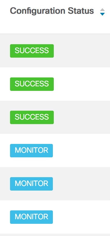
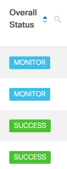
Choose Configure > Templates > Templates Library > Jobs.

The jobs are listed along with the Job ID, description and status. The latest task will be listed at the top.

Note 

If failover is triggered in Native HA, the Job ID sequence number is incremented by 32.

Step 2

Click Show Filter to filter the list.

In the Status column, use the drop-down to select the job status.

Step 3

Select a job and click the Delete icon to delete the job.

Step 4

To view the status of a job, click the Job ID radio button and click Status.

Step 5

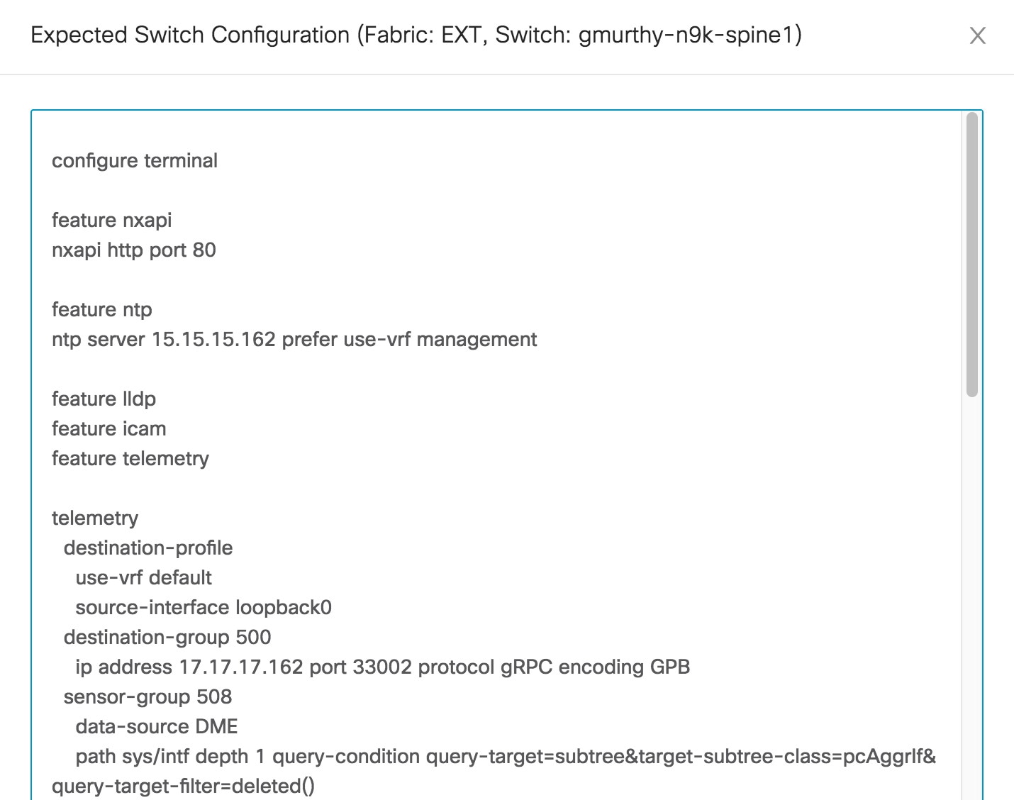
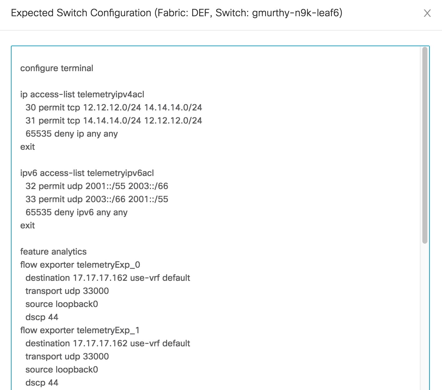
To view the command execution status for a device, click the radio button of a device name from the Devices table in the Job Execution Status window.

Note 
You can delete multiple jobs at once, but you cannot view the status of multiple jobs at once.

Backup

The Backup menu includes the following submenus:

Switch Configuration

This feature allows you to backup device configurations from running configuration as a regular text file in the file system. However, you can also perform operations on startup configuration. The backup files can be stored in the DCNM server host or on a file server.

You can also configure the archive system to support scheduling of jobs for the selected list of devices. You can configure only one job for a switch.

The following tables describe the icons and fields that appear on Configure > Backup > Switch Configuration.

Table 4. Switch Configuration Operations

Icon

Description

Copy Configuration to bootflash

Allows you to copy a configuration file of a switch to the bootflash of the selected destination switches.

View Configuration

Allows you to view the configuration file.

Delete Configuration

Allows you to delete the configuration file.

Compare Configuration

Allows you to compare two configuration files, from different devices or on the same device.

Export Configuration

Allows you to export a configuration file from the DCNM server.

Import User-Defined Configuration

Allows you to import a user-defined configuration file to the DCNM server.

Restore Configuration to devices

Allows you to restore configuration from the selected devices.

Archive Jobs

Allows you to add, delete, view, or modify the jobs.
Table 5. Switch Configuration Field and Description

Field

Description

Device Name

Displays the device name

Click the arrow next to the device to view the configuration files.

IP Address

Displays the IP address of the device.

Group

Displays the group of the device.

Configuration

Displays the configuration files that are archived for that device.

Archive Time

Displays the time when the device configuration files were archived.

The format is Day:Mon:DD:YYYY HH:MM:SS.

Size

Displays the size of the archived file.

This section contains the following:

Copy Configuration

You can copy the configuration files to the same device, to another device, or multiple devices concurrently.

Perform the following task to view the status of tasks.

Procedure

Step 1

From Cisco DCNM home page, choose Configure > Backup > Switch Configuration. Select any startup/running/archive configuration of the device that you must copy.

Step 2

Click Copy Configuration to bootflash.

Copy Configuration to bootflash page appears, displaying the Source Configuration Preview and Selected Devices area.

Source Configuration Preview area shows the contents of running/startup/version configuration file which is copied to the devices.

Step 3

In the Selected Devices area, check the device name check box to copy the configuration to the device.

Note 

You can select multiple destination devices to copy the configuration.

The selected devices area shows the following fields:

  • Device Name—Specifies the target device name to which the source configuration is copied.

  • IP Address—Specifies the IP Address of the destination device.

  • Group—Specifies the group to which the device belongs.

  • Status—Specifies the status of the device.

Step 4

Click Copy.

A confirmation window appears.

Step 5

Click Yes to copy the configuration to the destination device configuration.


View Configuration

You can view or edit the configuration file on the device.

Perform the following task to view or edit the configuration file for the devices.

Procedure

Step 1

From Cisco DCNM home page, choose Configure > Backup > Switch Configuration. Click the arrow next to the device name to view the configuration files on the device. Select the configuration file radio button to view the configuration file.

Step 2

Click the View Configuration.

The View Configuration window appears showing the configuration file content.


Delete Configuration

Perform the following task to delete the configuration file from the device.


Note

Ensure that you take a backup of the configuration file before you delete.


Procedure

Step 1

From Cisco DCNM home page, choose Configure > Backup > Switch Configuration. Click the arrow next to the device name to view the configuration files on the device.

Step 2

Click the configuration file radio button to be deleted.

Note 

You can delete multiple configuration files. However, you cannot delete startup, or running configuration files.

Step 3

Click Yes to delete the configuration file.


Compare Configuration Files

This feature allows you to compare the configuration file with another version of the same device or with the configuration file of another device.

Perform the following task to compare the configuration files.

Procedure

Step 1

Navigate to Configure > Backup > Switch Configuration. Click the arrow next to the device name to view the configuration files on the device.

Step 2

Check the check box and select two configuration files to compare.

The first file that you selected is designated as Source and the second configuration file is designated as the Target file.

Step 3

Click Compare Configuration.

View Config Diff page appears, displaying the difference between the two configuration files.

The Source and Target configuration files content is displayed in two columns. From the drop-down list in the right-top corner, choose All to view the entire configuration. You can also choose Changed to view the configuration differences of the configuration files.

The differences in the configuration file are show in the table, with legends.

  • Red: Deleted configuration details.

  • Green: New added configuration.

  • Blue: Modified configuration details.

Step 4

Click Copy to Target to copy the source configuration to the target configuration file. Click Cancel to revert to the configuration details page.

The Copy Configuration window displays the source configuration preview and the target device of the destination configuration. The selected devices area shows the following fields:

  • Device Name—Specifies the target device name to which the source configuration is copied.

  • IP Address—Specifies the IP Address of the destination device.

  • Group—Specifies the group to which the device belongs.

  • Status—Specifies the status of the device.

Step 5

Click Yes to copy the configuration to the destination device configuration.


Export Configuration

You can export a configuration file from the Cisco DCNM server. Perform the following task to export a configuration file.

Procedure

Step 1

From Cisco DCNM home page, choose Configure > Backup, select a configuration to export.

Step 2

Click Export Configuration.

The files are downloaded in your local system. You can use the third-party file transfer tools to transfer these files to an external server.


Import Configuration File

You can import the configuration file from the file server to the Cisco DCNM.

Perform the following task to import a single or multiple configuration files.

Procedure

Step 1

From Cisco DCNM home page, choose Configure > Backup > Switch Configuration and click Import User-Defined Configuration.

The file server directory opens.

Step 2

Browse the directory and select the configuration file that you want to import. Click Open.

A confirmation screen appears.

Note 

The file name should not contain forward slash (/) or backward slash (\).

The file name can be alphanumeric. It can also have a period (.), underscore (_), and a space. You can import only files with the .cfg extension.

Step 3

Click Yes to import the selected file.

The imported configuration file appears as a User Imported file.


Restore Configuration

You can restore the configuration file from the selected switches. From Cisco DCNM Release 11.0(1), you can restore configuration based on the selected date as well.


Note

You cannot restore the configuration for SAN switches and FCoE-enabled switches.


Perform the following task to restore the configuration from the selected devices.

Procedure

Step 1

From Cisco DCNM home page, choose Configure > Backup > Switch Configuration, and click Restore.

Step 2

Select the type of restore from the drop-down list. You can choose Version-based or Date-based.

Note 
  • If you choose date-based restore, you have to select the date and time. The configuration available before the mentioned time is restored.

  • If you choose version-based restore, you have to choose a configuration from the Configuration column. You can view the configuration details in the View column.

Step 3

Check the Device Name check box from which you want to restore the configuration. Click Restore.

The Devices area shows the following fields:

  • Device Name—Specifies the device name from which the configuration file is restored.

  • IP Address—Specifies the IP Address of the device.

  • Group—Specifies the group to which the device belongs.

  • Status—Specifies the status of the device.

Note 

You can restore the configuration only from the same device. If you select user-imported configuration files, you can restore configuration for any number of devices.


Archive Jobs

This section contains context-sensitive online help content under Cisco DCNM Configure > Backup > Switch Configuration >Archive Jobs.

DCNM switch archive jobs list SNMPv3 as a requirement. Error cause in job execution is "Switch is not managed using SNMPv3", status is "Not Eligible". This is not documented.


Note

The configuration files from the archived jobs are located in the DCNM Server directory: \dcm\dcnm\data\archive\<dcnm-ip-address>\. You can use the third-party file transfer tools or file transfer commands to transfer these files to an external server.


The following table describes the fields that appear on the Archive Jobs window.

Field

Description

User

Specifies who created this job.

Group

Specifies the group to which this job belongs.

Group Job

Specifies whether it is a group job or a per-device job. The values are true or false.

Schedule

Specifies the schedule of the job. Also show the recurrence information.

Last Execution

Specifies the date and time at which this job was last executed.

Job Status

Specifies if the job was successful, scheduled, running, or failure.

Note 

Running and Scheduled status is not applicable for existing jobs in an upgraded Cisco DCNM.

Status shows Not Eligible and an error appears Switch is not managed using SNMPv3, when SNMPv3 is not enabled on DCNM.

User Comments

Specifies the comments or description provided by the user.
Archive Jobs

To add, delete or view the job from the Cisco DCNM Web UI, perform the following steps:


Note

You must set the SFTP/TFTP/SCP credentials before you configure jobs. On the DCNM Web Client, navigate to Administration > DCNM Server > Archive FTP Credentials to set the credentials.


Procedure

Step 1

Choose Configure > Backup > Switch Configuration > Archive Jobs > Archive Jobs tab, and click Add Job.

The Create Job screen displays the Schedule, Device Selection and Selected Devices.

A backup is scheduled as defined.

  1. In the Schedule area, configure the start time, repeat interval and repeat days.

    • Start At: Configure the start time using the hour:minutes:second drop-down lists.

      • Once: Configure the job to be executed once, on the particular day. The time at which this job will be executed is determined by the Start At field.

      • Now—Configure the job to be executed immediately. Cisco DCNM will consider the default date and time as configured on the server.

        Note 

        You can schedule a job to run Now even if a job is already scheduled.

      • Daily: Check the check box on the days you want this job to be executed. The time at which this job will be executed is determined by the Start At field.

      • Real Time: Configure the job to be executed if there is any configuration changes in the device. The device must be quiet for 5 minutes, after which the DCNM Sever will execute this job.

    • Repeat Interval: Check the Repeat Interval check box to repeat the job at scheduled intervals. Configure the intervals using either days or hours drop-down list.

    • Comments: Enter your comments, if any.

  2. In the Device Selection area, use the radio button to choose one of the following:

    • Device Group: Click the Device Group radio button to select the entire group of devices for this job.

      Select the Device Group from the drop-down list.

      Note 

      When the devices are not licensed, they will not be shown under the group on the Cisco DCNM Configure > Backup > Switch Configuration > Archive Jobs. When none of the devices under a group is licensed, the group alone will be shown with no devices, until a device under that group is licensed.

    • Selected Devices: Click the Selected Devices radio button to select one of multiple devices from various groups for this job.

      Select the devices from the drop-down list.

      From Cisco DCNM Release 11.2(1), you can apply VRF for all the selected devices simultaneously. You can either apply Management VRFs or Default VRFs.

    Note 

    When the SAN and LAN credentials are not configured for a switch, it will not be listed in the Selected Devices drop-down list. To configure, navigate to Administration > Credentials Management > SAN Credentials and Administration > Credentials Management > LAN Credentials.

  3. In the Selected Devices area, the following fields are shown:

    • Name: Specifies the name of the device on which the job is scheduled.

    • IP Address: Specifies the IP Address of the device.

    • Group: Specifies the group to which the device belongs.

    • VRF: Specifies the virtual routing and forwarding (VRF) instance.

      Select a VRF type to modify the existing VRF type to the specified device. You can either apply Management VRFs or Default VRFs.

    Note 

    If a job for a device exists under device level, you can create a group level job which includes this switch as part of that group. However, this switch will be excluded during the execution of the job.

  4. Click Create to add a new job.

Step 2

To delete a job, from the Cisco DCNM home page, choose Configure > Backup > Switch Configuration > Archive Jobs > Archive Jobs, and select a job.

  1. Click Delete Job.

    The Schedule, Device Selection and the Selected devices for this job is displayed.

  2. Click Delete.

Step 3

To view the details of the job, from the Cisco DCNM home page, choose Configure > Backup > Switch Configuration > Archive Jobs > Archive Jobs, and check the job check box.

  1. Click View/Modify Job.

    The Schedule, Device Selection and the Selected devices for this job is displayed.

  2. Modify the required details. Click OK to revert to view the list of jobs.

    Note 
    • You cannot modify a job that is scheduled to be run Now to one that is scheduled to be run Daily.

    • You cannot modify the repeat interval duration for an archive job. When you try to modify, the operation fails and the job is deleted. You must delete existing repeat interval archive job and create a new job.


What to do next

You can also configure the Cisco DCNM to retain the number of archived files per device. Choose Administration > DCNM Server > Server Properties, and update the archived.versions.limit field.

Job Execution Details

The Cisco DCNM Web Client > Configure > Backup > Switch Configuration > Archive Jobs > Archive Jobs > Job Execution Details tab shows the following tabs in the Job Execution History table.

Field

Description

Job Name

Displays the system-generated job name.

User

Specifies the persona of the person who created the job.

Device Group

Specifies fabric or the LAN group under which the job was created.

Device

Specifies the IP Address of the Device.

Server

Specifies the IP Address of the DCNM Server to which the device is associated with.

Protocol

Specifies if the SFTP, TFTP, or SCP protocol is applied.

Execution time

Specifies the time at which the job was last executed.

Status

Specifies the status of the job.

  • Skipped

  • Failed

  • Successful

Error Cause

Specifies the error if the job has failed. The categories are as follows:

  • No change in the configuration.

  • Switch is not managed by this server.

Note 

If the error cause column is empty, it implies that the job was executed successfully.

Hover over the error cause to view the complete description.

Archives

A user with network operator role can view configuration archives for a switch and their details in the Archives window.

The following tables describe the icons and fields that are displayed in this window.

Table 6. Archive Operations

Icon

Description

Compare

Allows you to compare two configuration files either from different devices or on the same device.

View

Allows you to view a configuration file.

Table 7. Archive Field and Description

Field Name

Description

Device Name

Displays the device name

Click on the arrow next to the device to view the configuration files.

IP Address

Displays the IP address of the device.

Group

Displays the group of the device.

Configuration

Displays the configuration files that are archived for that device.

Archive Time

Displays the time at which the device configuration files were archived.

The format is Day:Mon:DD:YYYY HH:MM:SS.

Size

Displays the size of the archived file.

This section contains the following:

Compare Configuration Files

You can compare one version of a configuration file with another version of the same configuration file in the same device, or the configuration files of two different devices.

To compare the configuration files from the Cisco DCNM Web UI, perform the following steps:

Procedure

Step 1

Choose Configure > Backup > Archives.

Step 2

In the Archives area, click the arrow that is adjacent the name of the device whose configuration files you want to view. The list of configuration files is displayed.

Step 3

Check the check box next to configuration files and select two configuration files to compare.

The first file that you select is designated as the source and the second configuration file is designated as the target file.

Step 4

Click Compare.

The View Config Diff page displays the difference between the two configuration files.

The Source and Target configuration files content are displayed in two columns. Choose All from the drop-down list in the right-top corner to view the entire configuration. Choose Changed to view the configuration differences between the configuration files.

The differences in the configuration files are shown in a table, with legends.

  • Red: Deleted configuration details.

  • Green: New added configuration.

  • Blue: Modified configuration details.


View Configuration

You can view an archived configuration file.

To view or edit the configuration file for the devices from the Cisco DCNM Web UI, perform the following steps:

Procedure

Step 1

Choose Configure > Backup > Archives.

The Archives window is displayed.

Step 2

Click the arrow that is next to the name of the device whose configuration files you want to view.

The list of configuration files are displayed.

Step 3

Select the radio button that is next to the corresponding file you want to view.

Step 4

Click the View configuration icon.

The View configuration window appears showing the configuration file content in the right column.


Network Config Audit

Cisco DCNM provides auditing for the configuration changes across the network switches. The Network Audit Reporting feature enables you to a generate audit report so that you can track the added, deleted, or modified configurations. You will be able to generate the network audit reports only when you have existing archival jobs. Using the generated reports, you can view the config differences on a device for a specified period.

This section contains the following:

Generating Network Config Audit Reports

To generate the network config audit reports from the Cisco DCNM Web UI, perform the following steps:
Procedure

Step 1

Choose Configure > Backup > Network Config Audit.

The Network Audit Report window is displayed.

Step 2

In the Devices drop-down list, choose the devices to generate a report.

Step 3

Specify the Start Date and the End Date.

Step 4

Click Generate Report to view the configuration differences. The configuration differences are color-coded.

  • Red: Deleted Configuration
  • Green: Newly Added Configuration
  • Blue: Changed configuration
  • Strikethrough: Old configuration

After you generate a report, you can export the configuration reports into an HTML file.


Creating a Network Config Audit Report
To create a network config audit job and view the configuration differences between the devices from the Cisco DCNM Web UI, perform the following steps:
Procedure

Step 1

Choose Monitor > Report > Generate.

The left pane shows various reports that you can create.

Step 2

Choose Common > Network Config Audit.

Step 3

In the Report Name field, enter the name of the report.

Step 4

In the Repeat field, choose the appropriate repeat interval, that is, Daily, Weekly, or Monthly.

Daily job generates a report of configuration differences for all the selected devices for last 1 day. Weekly job generates a report for the last 7 days, and the monthly job generates a report for the last 30 days.

Step 5

In the Start and End date fields, specify the start and end date for the report.

Step 6

In the Email Report field, specify the email delivery options.

  • No: Select this option if you do not want to send the report through email.
  • Link Only: Select this option if you want to send the link to the report.
  • Contents: Select this option if you want to send the report content.

If you select Link Only or the Contents option, enter the email address and subject in the To and Subject fields.


Monitoring Network Config Audit Report
To monitor the network config audit report from the Cisco DCNM Web UI, perform the following steps:
Procedure

Step 1

Choose Monitor > Report > View.

Step 2

Choose Common > Network Config Audit in the left pane to the network config audit reports.


Deleting a Network Config Audit Report
To delete a network config audit report from the Cisco DCNM Web UI, perform the following steps:
Procedure

Step 1

Choose Monitor > Report > View.

Step 2

Choose Common > Network Config Audit.

The View Reports window is displayed with the reports that you have created.

Step 3

Select the reports that you want to delete, and click the Delete icon.


Image Management

Upgrading your devices to the latest software version manually might take a long time and prone to error, which requires a separate maintenance window. To ensure rapid and reliable software upgrades, image management automates the steps associated with upgrade planning, scheduling, downloading, and monitoring. Image management is supported only for Cisco Nexus switches and Cisco MDS switches.


Note

Before you upgrade, ensure that the POAP boot mode is disabled for Cisco Nexus 9000 Series switches and Cisco Nexus 3000 Series switches. To disable POAP, run the no boot poap enable command on the switch console. You can however, enable it after the upgrade.


The Image Management menu includes the following submenu:

Upgrade [ISSU]

The Upgrade [ISSU] menu includes the following submenus:

Upgrade History [ISSU]

This feature enables you to upgrade the Cisco Nexus Platform Switches using In-Service Software Upgrade (ISSU). This upgrade procedure may be disruptive or non-disruptive based on the device configuration. You can select the Kickstart, System, or SSI images required for the upgrade from a remote server using SFTP, SCP, TFTP, FTP or from image repository or the file system on the device. Image repository can use SCP, SFTP, FTP, or TFTP as file transfer protocol. To select the images from the repository, the same needs to be uploaded from Configure > Image Management > Repositories tab.

The following table describes the fields that appear on Configure > Image Management > Upgrade [ISSU] > Upgrade History.

Field

Description

Task Id

Specifies the serial number of the task. The latest task will be listed in the top.

Note 
If Failover is triggered in Native HA, the Task Id sequence number is incremented by 32.

Task Type

Specifies the type of task.

  • Compatibility

  • Upgrade

Owner

Based on the Role-Based Authentication Control (RBAC), specifies the owner who initiated this task.

Devices

Displays all the devices that were selected for this task.

Job Status

Specifies the status of the job.

  • Planned

  • In Progress

  • Completed

  • Completed with Exceptions

    Note 

    If the job fails on a single or multiple devices, the status field shows COMPLETED WITH EXCEPTION indicating a failure.

Created Time

Specifies the time when the task was created.

Scheduled At

Specifies the time when the task is specified to be executed. You can also choose to schedule a task to be executed at a later time.

Completed Time

Specifies the time when the task was completed.

Comment

Shows any comments that the Owner has added while performing the task.


Note

After a fresh Cisco DCNM installation, this page will have no entries.


You can perform the following:

New Installation

To upgrade the devices that are discovered from the Cisco DCNM, perform the following steps:

Procedure

Step 1

Choose Configure > Image Management > Upgrade [ISSU] > Upgrade History.

Step 2

Choose New Installation to install, or upgrade the kickstart and the system images on the devices.

The devices with default VDCs are displayed in the Select Switches window.

Step 3

Select the check box to the left of the switch name.

You can select more than one switch and move the switches to the right column.

Step 4

Click Add or Remove icons to include the appropriate switches for upgrade.

The selected switches appear in a column on the right.

Step 5

Click Next.

The Pre-Post ISSU Reports window appears.

Note 

Pre-Post ISSU Reports are not supported in SAN and Media Controller installations.

Step 6

Click Next.

The Specify Software Images window appears. This tab displays the switches that you selected in the previous screen. You can choose the images for upgrade as well.

  • The Auto File Selection check box enables you to specify a file server, an image version, and a path where you can apply the upgraded image to the selected devices.
  • In the Select File Server drop-down list, select the one of the file servers that is created in the Cisco DCNM repositories.

  • In the Image Version field, specify the image version. For example, enter 7.3.9.D1.1 in the Image Version field if you have selected m9700-sf3ek9-kickstart-mz.7.3.0.D1.1.bin as the image version.
  • In the Path field, specify the image path. Specify an absolute path if you choose SCP or SFTP. For example, //root/images/. Specify a relative path to the FTP or TFTP home directory if you choose FTP or TFTP. Specify the absolute path of the image if you’re using TFTP server that is provided by Cisco DCNM, local DCNM TFTP. You can’t use the same DCNM TFTP server for creating another job when the current job is in progress.

Step 7

Click Select Image in the Kickstart image column.

The Software Image Browser dialog box appears.

Note 
  • Cisco Nexus 3000 Series and 9000 Series Switches require only the system image to load the Cisco NX-OS operating system. Therefore, the option to select kickstart images for these devices is disabled.

  • If there’s an issue in viewing the Software Image Browser dialog box, reduce the font size of your browser and retry.

Step 8

Click Select Image in the System Image column.

The Software Image Browser dialog box appears.

Step 9

On the Software Image Browser dialog box, you can choose the image from File Server or Switch File System.

If you choose File Server:

  1. From the Select the File server list, choose the appropriate file server on which the image is stored.

    The servers at Configure > Image Management > Repositories are displayed in the drop-down list.

  2. From the Select Image list, choose the appropriate image. Check the check box to use the same image for all other selected devices of the same platform.

    Example: For platform types N7K-C7009 and N7K-C7010, logic matches platform (N7K) and three characters (C70) from subplatform. The same logic is used across all platform switches.

    Note 

    Only files with BIN extension are listed if you select File Server. To view other files, choose Administration > DCNM Server > Server Properties, set FILE_SELECTION_FILTER to false, and restart the server. It is set to true by default.

  3. Choose a VRF from the Select Vrf drop-down list.

    Note 

    This field does not appear for Cisco MDS switches.

    This VRF is selected for other selected devices by default. The default value is management.

  4. Click OK.

    If the file server selected is either ftp or tftp, in the text box, enter the relative path of the file from the home directory.

    This image is selected for all other selected devices of same platform type.

If you choose Switch File System:

  1. From the Select Image list, choose the appropriate image that is located on the flash memory of the device.

    Note 

    Only files with BIN extension are listed if you select Switch File System. To view other files, choose Administration > DCNM Server > Server Properties, set FILE_SELECTION_FILTER to false, and restart the server. It is set to true by default.

  2. Click OK to choose the kickstart image or Cancel to revert to the Specify Software Images dialog box.

Step 10

The Vrf column indicates the name of the virtual routing and forwarding (VRF).

VRF is not applicable for Cisco MDS devices.

Step 11

In the Available Space column, specify the available space for the Primary Supervisor and Secondary Supervisor modules of the switch.

Available Space column shows the available memory in MB on the switch (for less than 1 MB, it’s shown and marked as KB).

Bootflash browser shows the filename, size, and last modified date for all the files and directories on the switch bootflash. You can delete files by selecting them and clicking Delete to increase the available space on the switch.

Step 12

Selected Files Size column shows the size of images that are selected from the SCP or SFTP server.

If the total size of selected images is greater than available space on a switch, the file size is marked in red. We recommend that you create more space on the switch to copy images to it and install.

Step 13

Drag and drop the switches to reorder the upgrade task sequence.

Step 14

(Optional) Uncheck Skip Version Compatibility check box if you want to check the compatibility of Cisco NX-OS software version on your device with the upgraded images that you chose.

Step 15

Select Select Parallel Line Card upgrade to upgrade all the line cards at the same time.

Upgrading a parallel line card isn’t applicable for Cisco MDS devices.

Step 16

Click Options under the Upgrade Options column to choose the type of upgrade.

Upgrade Options window appears with two upgrade options. The drop-down list for Upgrade Option 1 has the following options:

  • Disruptive

  • Bios force

  • Allow non-disruptive

  • Force non-disruptive

Disruptive is the default value for Cisco Nexus 9000 Series switches. The upgrade option is Not Applicable for other switches.

When you choose Allow non-disruptive under Upgrade Option 1 and if the switch does not support non-disruptive upgrade, then it will go through a disruptive upgrade.

When you choose Force non-disruptive under Upgrade Option 1, the Skip Version Compatibility check box will be unchecked because compatibility check is mandatory for non-disruptive upgrade. If the switches you choose do not support non-disruptive upgrade, a warning message appears asking you to review the switch selection. Use the check boxes to choose or remove switches.

The drop-down list for Upgrade Option 2 has the following options when you choose Allow non-disruptive or Force non-disruptive under Upgrade Option 1:

  • NA

  • bios-force

When you choose Disruptive or Bios-force under Upgrade Option 1, Upgrade Option 2 is disabled.

Check the Use this Option for all other selected devices check box to use the selected option for all the selected devices and click OK.

Note 
  • The upgrade options are applicable only for Cisco Nexus 3000 Series and 9000 Series switches.

  • Selecting the Allow non-disruptive option for upgrading does not ensure a non-disruptive upgrade. Perform a compatibility check to ensure that the device supports non-disruptive upgrade.

Step 17

Click Next.

If you didn’t select Skip Version Compatibility, the Cisco DCNM performs a compatibility check.

You can choose to wait until the check is complete or click Finish Installation Later.

The installation wizard is closed and a compatibility task is created in Configure > Image Management > Upgrade [ISSU] > Upgrade History tasks.

The time that is taken to check the image compatibility depends on the configuration and the load on the device.

The Version Compatibility VerificationCompatibility Verification status column displays the status of verification.

If you skip the version compatibility check by choosing Skip Version Compatibility, Cisco DCNM displays only the name of the device. The Current Action column displays Completed, and the Compatibility Verification column displays Skipped.

You can review the switch selection and check or uncheck the switches for upgrading accordingly.

Step 18

Click Finish Installation Later to perform the upgrade later.

Step 19

Click Next.

Step 20

Check the Next check box to put a device in maintenance mode before upgrade.

Step 21

Check the check box to save the running configuration to the startup configuration before upgrading the device.

Step 22

You can schedule the upgrade process to occur immediately or later.

  1. Select Deploy Now to upgrade the device immediately.

  2. Select Choose time to Deploy and specify the time in MMM/DD/YYYY HH:MM:SS format to perform the upgrade later.

    This value is relative to the server time. If the selected time to deploy is in the past, the job is executed immediately.

Step 23

You can choose the execution mode based on the devices and the line cards you have chosen to upgrade.

  1. Select Sequential to upgrade the devices in the order you chose them.

    Note 

    This option is disabled if you put the device in maintenance mode.

  2. Select Concurrent to upgrade all the devices at the same time.

Step 24

Click Finish to begin the upgrade process.

The Installation wizard closes and a task to upgrade is created on the Configure > Image Management > Upgrade [ISSU] > Upgrade History page.


What to do next
After you complete the ISSU on the switch, ensure that you wait for 20 minutes to allow the switch to reboot, and stabilize the SNMP agent. DCNM discovers polling cycles in order to display the new version of the switch on the Cisco DCNM Web UI.
Finish Installation

You can choose to complete the installation for tasks which was completed on the Compatibility Check page. Perform the following task to complete the upgrade process on the devices.

Procedure

Step 1

Choose Configure > Image Management > Upgrade [ISSU] > Upgrade History, select a task for which the compatibility check is complete.

Select only one task at a time.

Step 2

Click Finish Installation.

Software Installation Wizard appears.

Step 3

Review the switch selection and check or uncheck the switches for upgrading accordingly.

Step 4

Check the check box to save the running configuration to the startup configuration before upgrading the device.

Step 5

Check the check box to put a device in maintenance mode before upgrade. This option is valid only for the devices that support maintenance mode.

Step 6

You can schedule the upgrade process to occur immediately or later.

  1. Select Deploy Now to upgrade the device immediately.

  2. Select Choose time to Deploy and specify the time in DD/MM/YYYY HH:MM:SS format to perform the upgrade later.

Step 7

You can choose the execution mode that is based on the devices and the line cards that you have chosen to upgrade.

  1. Select Sequential to upgrade the devices in the order in which they were chosen.

    Note 

    This option is disabled if you put the device in maintenance mode.

  2. Select Concurrent to upgrade the devices at the same time.

Step 8

Click Finish to complete the upgrade process.


View

To view the image upgrade history from the Cisco DCNM Web UI, perform the following steps:

Procedure

Step 1

Choose Configure > Image Management > Upgrade [ISSU] > Upgrade History, check the task ID check box.

Select only one task at a time.

Step 2

Click View.

The Installation Task Details window appears.

Step 3

Click Settings. Expand the Columns menu and choose the details you want to view.

You can view the following information in this window:

  • Location of the kickstart and system images

  • Compatibility check status

  • Installation status

  • Descriptions

  • Logs

Step 4

Select the device.

The detailed status of the task appears. For the completed tasks, the response from the device appears.

If the upgrade task is in progress, a live log of the installation process appears.

Note 
  • This table autorefreshes every 30 secs for jobs in progress, when you’re on this window.

  • The switch-level status for an ongoing upgrade on a Cisco MDS switch doesn't appear for other users without SAN credentials. To apply SAN Credentials, choose Administration > Credentials Management > SAN Credentials.


Delete

To delete a task from the Cisco DCNM Web UI, perform the following steps:

Procedure

Step 1

Choose Configure > Image Management > Upgrade [ISSU] > Upgrade History, and check the Task ID check box.

Step 2

Click Delete.

Step 3

Click OK to confirm deletion of the job.


Switch Level History

You can view the history of the upgrade process at a switch level. You can view the current version of the switch and other details.

The following table describes the fields that appear on Configure > Image Management > Upgrade [ISSU] > Switch Level History.

Field

Description

Switch Name

Specifies the name of the switch

IP Address

Specifies the IP Address of the switch

Platform

Specifies the Cisco Nexus switch platform

Current Version

Specifies the current version on the switch software

Click the radio button next to a switch name to select the switch and view its upgrade history. Click View to view the upgrade task history for the selected switch.

The following table describes the fields that appear on Configure > Image Management > Upgrade [ISSU] > Switch Level History > View Device Upgrade Tasks:

Field

Description

Owner

Specifies the owner who initiated the upgrade.

Job Status

Specifies the status of the job.

  • Planned

  • In Progress

  • Completed

KickStart Image

Specifies the kickStart image that is used to upgrade the Switch.

System Image

Specifies the system image that is used to upgrade the switch.

Completed Time

Specifies the date and time at which the upgrade was successfully completed.

Status Description

Specifies the installation log information of the job.

Patch [SMU]

The Patch [SMU] menu includes the following submenus:

Installation History

This feature allows you to activate or deactivate packages using Software Maintenance Update (SMU). Personnel with Admin privileges can perform this operation.

The following table describes the fields that appear on Configure > Image Management > Patch [SMU] > Installation History.

Field

Description

Task Id

Specifies the serial number of the task. The latest task is listed at the top.

The tasks are performed in the sequential order.

Switch Name

Specifies the name of the switch for which the patch file is installed.

IP Address

Specifies the IP Address of the device.

Task

Specifies if the patch is installed or uninstalled on this device.

Package

Specifies the name of the patch file.

Status

Specifies the status of installation or uninstallation of the patch files.

Status Description

Describes the status of installation or uninstallation of the patch files.

This section contains the following:

Install Patch

To install the patch on your devices from Cisco DCNM Web Client, perform the following steps:

Procedure

Step 1

Choose Configure > Image Management > Patch [SMU] > Installation History, click Install.

The Select Switches window appears. All the Cisco Nexus switches that are discovered by Cisco DCNM are displayed.

Step 2

Select the check box to the left of a switch name.

You can select more than one device.

Step 3

Click Add or Remove icons to include the appropriate switches for installing the patch.

The selected switches appear in the right column.

Step 4

Click Next.

Step 5

Click Select Packages in the Packages column.

The SMU Package Browser dialog box appears.

Step 6

In the SMU Package Browser dialog box, you can choose the patch file from File Server or Switch File System.

If you choose File Server:

  1. From the Select the file server list, choose the appropriate file server on which the patch is stored.

    The servers, which are listed in the Repositories window, are displayed in the drop-down list. Choose Configure > Image Management > Repositories to view the Repositories window.

  2. From the Select Image list, choose the appropriate patch that must be installed on the device.

    You can select more than one patch file to be installed on the device.

    Note 

    If the patch installation results in the restart of the device, select only one patch file.

    Check the check box to use the same patch for all other selected devices of the same platform.

    Only files with BIN extension are listed if you select File Server. To view other files, choose Administration > DCNM Server > Server Properties, set FILE_SELECTION_FILTER to false, and restart the server. It is set to true by default.

  3. From the Select Vrf list, choose the appropriate virtual routing and forwarding (VRF).

    The two options in the drop-down list are management and default.

    Check the check box to use the same VRF for all other selected devices.

  4. Click OK to choose the patch image or Cancel to revert to the SMU installation wizard.

If you choose Switch File System:

  1. From the Select Image list, choose the appropriate patch file image that is located on the flash memory of the device.

    You can select more than one patch file to be installed on the device.

    Only files with BIN extension are listed if you select Switch File System. To view other files, choose Administration > DCNM Server > Server Properties, set FILE_SELECTION_FILTER to false, and restart the server. It is set to true by default.

  2. Click OK to choose the image, Clear Selections to uncheck all the check boxes, or Cancel to revert to the SMU Package Browser dialog box.

Step 7

Click Finish.

You will get a confirmation window. Click OK.

Note 

SMU installation may reload the switch if the SMU is reloaded.

You can view the list of patches that are installed on the switch in the Switches window by choosing DCNM > Inventory > Switches.


Uninstall Patch

To uninstall the patch on your devices from Cisco DCNM Web Client, perform the following steps:

Procedure

Step 1

Choose Configure > Image Management > Patch [SMU] > Installation History, click Uninstall.

The Select Switches page appears. The discovered Cisco Nexus switches are displayed.

Step 2

Check the check box on the left of the switch name.

You can select more than one image device.

Step 3

Click Add or Remove icons to include the appropriate switches for installing the patch.

The selected switches appear in a column on the right.

Step 4

Click Next.

The Active Packages page appears.

Step 5

Click Select Packages under the Installed Packages column.

The Packages Installed window appears, which lists the patches that are applied to the switch.

Step 6

Select the patches that you want to uninstall from this device.

You can select more than one patch that is applied on the device.

Note 

If the patch uninstallation results in the restart of the device, select only one patch.

Step 7

Click Finish to uninstall the patch from the device.

You will get a confirmation window. Click OK.

You can uninstall more than one patch at a time.

Note 

SMU uninstallation may reload the switch if the SMU is reloaded.


Delete Patch Installation Tasks

To delete the patch installation tasks from the Cisco DCNM Web UI, perform the following steps:

Procedure

Step 1

Choose Configure > Image Management > Patch [SMU] > Installation History, check the task ID check box.

Step 2

Click Delete.

Step 3

Click OK to confirm deletion of the patch installation task.


Switch Installed Patches

You can view the patches that are installed on all the switches in the network. You can refresh the view to see the latest installed patches.

The following table describes the fields that appear on Configure > Image Management > Patch [SMU] > Switch Installed Patches.

Field

Description

Switch Name

Specifies the name of the switch.

IP Address

Specifies the IP address of the switch.

Platform

Specifies the Cisco Nexus switch platform.

Installed Patches

Specifies the currently installed patches on switches.

Click Refresh to refresh the table.

Package [RPM]

The Package [RPM] menu includes the following submenus:

Package Installation [RPM]

The package [RPM] feature allows you to install RPM packages. This feature is available for the Cisco Nexus 9000 Series and 3000 Series Switches.

The following table describes the fields that appear on Configure > Image Management > Package [RPM] > Installation History.

Field

Description

Task Id

Specifies the serial number of the task. The latest task is listed in the top.

The tasks are performed in the sequential order.

Switch Name

Specifies the name of the switch for which the package file is installed.

IPAddress

Specifies the IP address of the device.

Task

Specifies if the package is installed or uninstalled on this device.

Package

Specifies the name of the package file.

Status

Specifies the status of installation or uninstallation of the package files.

Completed Time

Specifies the time at which the installation or uninstallation task completed.

Status Description

Describes the status of installation or uninstallation of the package files.

This section contains the following:

Install Package [RPM]

Perform the following task to install the package on your devices using Cisco DCNM Web client.

Procedure

Step 1

Choose Configure > Image Management > Package [RPM] > Installation History, click Install.

The Select Switches page appears.

Step 2

Check the check box on the left of the switch name.

You can select more than one device.

Step 3

Click Add or Remove to include appropriate switches for installing packaging.

The selected switches appear in a column on the right.

Step 4

Click Next.

Step 5

Click Select Packages in the Packages column.

The RPM Package Browser screen appears.

Step 6

Choose the package file from File Server or Switch File System.

If you choose File Server:

  1. From the Select the file server list, choose the appropriate file server on which the package is stored.

    The servers at Configure > Image Management > Repositories are displayed in the drop-down list.

  2. From the Select Image list, choose the appropriate package that must be installed on the device.

    You can select more than one package file to be installed on the device.

    Only files with RPM extension are listed if you select File Server. To view other files, choose Administration > DCNM Server > Server Properties, set FILE_SELECTION_FILTER to false, and restart the server. It is set to true by default.

    Check the check box to use the same package for all other selected devices of the same platform.

  3. Click OK to choose the patch image or Cancel to revert to the RPM Installation Wizard.

If you choose Switch File System:

  1. From the Select Image list, choose the appropriate package file image that is located on the flash memory of the device.

    You can select more than one package file to be installed on the device.

    Only files with RPM extension are listed if you select Switch File System. To view other files, choose Administration > DCNM Server > Server Properties, set FILE_SELECTION_FILTER to false, and restart the server. It is set to true by default.

  2. Click OK.

Step 7

In the Installation Type column, choose one of the installation types:

  • Normal—Fresh installation
  • Upgrade—Upgrading the existing RPM
  • Downgrade—Downgrading the existing RPM
Step 8

Click Finish.

You can view the list of packages that are installed on the switch, on the Web Client > Inventory > Switches page.

Note 

If you are using Cisco DCNM Release 10.1(2), in case of installation of reload RPMs, perform a manual install commit on the switch after it switch reloads.


Uninstall Package [RPM]

To uninstall the RPM on your devices from the Cisco DCNM Web UI, perform the following steps:

Procedure

Step 1

Choose Configure > Image Management > Package [RPM] > Installation History, click Uninstall.

The Select Switches window appears.

Step 2

Check the check box on the left of the switch name.

You can select more than one switch.

Step 3

Click the Add or Remove icons to include the appropriate switches for uninstalling the package.

The selected switches appear in a column on the right.

Step 4

Click Next.

The Active Packages page appears.

Step 5

Click Select Packages under the Installed Packages column.

The Packages Installed window appears, which lists the packages that are installed in the switch.

Step 6

Click Finish to uninstall the package from the device.

You will get a confirmation window. Click OK.

You can uninstall more than one package at a time.

Note 
  • If you are using Cisco DCNM Release 10.1(2), in case of uninstallation of reload RPMs, a manual install commit needs to be performed on the switch once the switch is reloaded.

  • RPM uninstallation may reload the switch if the RPM is reload RPM.


Delete Package Installation Tasks

To delete the package installation tasks from the history view from the Cisco DCNM Web UI, perform the following steps:

Procedure

Step 1

Choose Configure > Image Management > Package [RPM] > Installation History, select the task ID check box.

Step 2

Click Delete.

Step 3

Click OK to confirm deletion of the task.


Switch Installed Packages

You can view the RPM packages that are installed on all Switches in the network. You can refresh the view to see the latest installed packages.

The following table describes the fields that appear on Configure > Image Management > Packages [RPM] > Switch Installed Packages.

Field

Description

Switch Name

Specifies the name of the switch.

IP Address

Specifies the IP address of the switch.

Platform

Specifies the Cisco Nexus switch platform.

Installed Packages

Specifies the currently installed packages on the switches and the type of package. The installed packages can be base packages or non-base packages.

Click Refresh to refresh the table.

Maintenance Mode [GIR]

The Maintenance Mode [GIR] menu includes the following submenus:

Maintenance Mode

The maintenance mode allows you to isolate the Cisco Nexus Switch from the network to perform an upgrade or debug, using Graceful Insertion and Removal (GIR). When the switch maintenance is complete, you can return the switch to normal mode. When the switch is in the maintenance mode, all protocols are gracefully brought down and all physical ports are shut down. When the normal mode is restored, all the protocols and ports are initiated again.

Perform the following to change the system mode of the devices.

Procedure

Step 1

Choose Configure > Image Management > Maintenance Mode [GIR] > Maintenance Mode, check the switch name check box.

You can select multiple switches.

Step 2

Choose one of the following options under the Mode Selection column:

  • Shutdown

  • Isolate

Note 

Click the appropriate option before you change the mode.

Step 3

Click Change System Mode.

A confirmation message appears.

Step 4

Click OK to confirm to change the maintenance mode of the device.

The status of operation can be viewed in the System Mode and the Maintenance Status.


Switch Maintenance History

You can view the history of the maintenance mode changes executed from the Cisco DCNM.

The following table describes the fields that appear on Configure > Image Management > Maintenance Mode [GIR] > Switch Maintenance History.

Field

Description

Task Id

Specifies the serial number of the task. The latest tasks that are listed in the top.

Switch Name

Specifies the name of the switch for which the maintenance mode was changed.

IP Address

Specifies the IP address of the switch.

User

Specifies the name of the user who initiated the maintenance.

System Mode

Specifies the mode of the system.

Maintenance Status

Specifies the mode of the maintenance process.

Status

Specifies the status of the mode change.

Completed Time

Specified the time at which the maintenance mode activity was completed.

Click the radio button next to the switch name to select the switch for which you need to view the upgrade history. Click View to view the upgrade task history for the selected switch.

The following table describes the fields that appear on Configure > Image Management > Upgrade [ISSU] > Switch Level History > View > Upgrade Tasks History

Field

Description

Owner

Specifies the owner who initiated the upgrade.

Job Status

Specifies the status of the job.

  • Planned

  • In Progress

  • Completed

KickStart Image

Specifies the kickstart image that is used to upgrade the Switch.

System Image

Specifies the system image that is used to upgrade the switch.

Completed Time

Specifies the date and time at which the upgrade was successfully completed.

Image and Configuration Servers

To view the Image and Configuration Servers window from the Cisco DCNM Web UI homepage, choose Configure > Image Management > Repositories.

You can view the following details in the Image and Configuration Servers window.

Field

Descriptions

Name

Specifies the name of the repository you upload.

URL

Specifies the path where you uploaded the repository.

Username

Specifies the username of the remote server.

Last Modified

Specifies the date and timestamp of the last modification.

Add Image or Configuration Server URL

To add an image or a configuration server URL to the repository from the Cisco DCNM Web UI, perform the following steps:

Procedure

Step 1

On the Image and Configuration Servers window, click the Add icon.

The Add Image or Configuration Server URL window is displayed.

Step 2

Specify a name for the image.

Step 3

Click the radio button to select the protocol.

The available protocols are SCP, FTP, SFTP, and TFTP. Use the SCP protocol for POAP and Image Management.

You can use IPv4 and IPv6 addresses with these protocols.

Step 4

Enter the hostname or IP address and the path to download or upload files.

Note 

If you choose SCP or SFTP protocol and the path is root or /directory, adding an image or configuration server will not be successful.

Step 5

Specify the username and password.

Step 6

Click OK to save.


Deleting an Image

To delete an image from the repository from the Cisco DCNM Web UI, perform the following steps:

Procedure

Step 1

Choose Configure > Image Management > Repositories.

The Image and Configuration Servers window appears.

Step 2

Choose an existing image from the list and click the Delete Image icon.

A confirmation window appears.

Step 3

Click Yes to delete the image.


Editing an Image or Configuration Server URL

To edit an image or a configuration server URL to the repository from the Cisco DCNM Web UI, perform the following steps:

Procedure

Step 1

On the Image and Configuration Servers window, select an existing image and configuration server from the list, and click Edit.

Step 2

In the Edit Image or Configuration Server URL window, edit the required fields.

Step 3

Click OK to save or click Cancel to discard the changes.


File Browser

You can view the contents of the server on the Image and Configuration Servers page.

  1. In the Image and Configurations page, check the Server Name check box to view the content.

  2. Click File Browser to view the contents of this server.

Image Upload

To upload different types of images to the server from the Cisco DCNM Web UI, perform the following steps:


Note

Devices use these images during POAP or image upgrade.

Your user role should be network-admin to upload an image. You can’t perform this operation with the network-stager user role.


Procedure

Step 1

Choose Configure > Image Management > Repositories.

The Image and Configuration Servers window appears.

Step 2

Click Image Upload.

The Select File to Upload dialog box appears.

Step 3

Click Choose file to choose a file from the local repository of your device.

Step 4

Choose the file and click Upload.

Step 5

Click OK.

The upload takes some time depending on the file size and network bandwidth.


LAN Telemetry Health

Starting from DCNM 11.2(1), Streaming LAN Telemetry preview feature in DCNM is obsolete and is replaced by Network Insights Resources (NIR) application. NIR can be deployed using Cisco DCNM Applications Framework on Web UI > Applications. After the NIR is enabled on a fabric, you can monitor the status on the window in the Cisco DCNM Web UI.

When the connection status is shown as Disconnected the port configuration may not be accepted by the switch correctly. On the switch image 7.0(3)I7(6), if a switch already had nxapi configuration, and later it was managed by DCNM and telemetry was enabled on that fabric, DCNM pushes http port 80 configuration so that it could query some NXAPI commands such as show telemetry transport and show telemetry data collector details , to monitor telemetry connection statistics. In this case, the switch does not update http port 80 in its configuration even though the command was executed correctly. In such a scenario, issue the following commands on the switch:

switch# configure
switch(config)# no feature nxapi
switch(config)# feature nxapi
switch(config)# http port 80

Note

ICAM telemetry commands such as forwarding TCAM and ACL TCAM are not supported on Cisco Nexus C9504, C9508, and C9516 Series platforms for switch images 7.0(3)I7(5) and 7.0(3)I7(6)


LAN Telemetry has the following topics:

Health

Cisco DCNM allows you to monitor the configuration health attributes of Software Telemetry and Flow Telemetry for each fabric. The attributes are displayed for a particular fabric or all fabrics based on the selected SCOPE. Data Center scope displays all fabrics by default.

Software Telemetry

The following table describes the fields that appear in the LAN Telemetry > Health > Software Telemetry window.

Field Description
Fabric Name

Displays the fabric name.

Switch Name

Displays the switch name.

Switch IP

Displays the switch management IP address.

Switch Serial

Displays the switch serial number.

This column is hidden by default. Click the Settings icon, and check the Switch Serial check box to add it to the columns displayed.

Switch Model

Displays the switch model.

This column is hidden by default. Click the Settings icon, and check the Switch Model check box to add it to the columns displayed.

Switch Version

Displays the switch image version.

This column is hidden by default. Click the Settings icon, and check the Switch Version check box to add it to the columns displayed.

Receiver IP Port

Displays the receiver IP and port assigned to a switch to transport telemetry data.

The assigned IP and port will be based on the configured telemetry network, out-of-band or in-band, and the corresponding receiver microservice that is running in NIR application.

Receiver Status

Displays the status of the connection used to transport telemetry data between the switch and the receiver running in the NIR application.

The telemetry manager polls the switch for the connection status every 5 mins.

The valid values are:

  • Connected: The status is Connected when the telemetry manager is able to poll the receiver connection status from the switches.

  • Disconnected: If the status is Disconnected, the reason is mentioned in the Status Reason column.

  • Null: The status is Null when the telemetry manager in DCNM has not polled the receiver connection status from the switches or when it has not received any response from the switch for that request. When the receiver status is Null and if the configuration status is MONITOR or SUCCESS, log into the switch and check the nxapi configuration.

When you enable telemetry on a fabric that is managed by DCNM, the telemetry manager pushes the httpport 80 configuration. If the switch does not have httpport 80 configuration, run the following commands on the switch:

switch# configure terminal
switch(config)# no feature nxapi 
switch(config)# feature nxapi 
switch(config)# http port80
Configuration Type Displays the connection type ex: gRPC as reported by the switch. This value is obtained as part of the receiver connection status response from the switch. This column is hidden by default. It can be selected by clicking on the settings button.
Expected Config

Click the Expected Config icon to view the expected configuration for the switch in a dialog box. In case of error, the error reason will be displayed in the output.

Configuration Status

Displays the telemetry configuration switch summary status.

The valid values are:

  • MONITOR: Implies that the switch in the fabric was configured as Monitored in the NIR app. In this case, configure these switches manually with the telemetry configurations as displayed in the Expected Config column.

  • PROCESSING: Implies that the switch belonging to the fabric was configured as Managed in the NIR app. In this case, the telemetry manager will configure the switches and when configuration is in progress, it is displayed as PROCESSING.

  • SUCCESS: Implies that the switches were successfully configured.

  • PARTIAL SUCCESS: Implies that some of the telemetry configurations could not be pushed to the switches. The Status Reason column will indicate the failure reason.

  • FAILED: Implies that the DCNM job failed to configure the switches. It could happen that some configuration did get pushed to the switches while some did not, in that case also DCNM marks the whole job as Failed. The Status Reason column will indicate the failure reason.

You can filter the switches based on a particular status using the search option or you can sort the switches based on the status.

Sensor Status

Displays the sensor configuration status in a distributed color format. The sensor count is divided into three categories:

  • Green color (Success): Number of sensor paths that got configured successfully

  • Yellow color (Pending): Number of sensor paths that are pending to be configured

  • Red color (Failed): Number of sensor paths that could not be configured

Status Reason Displays the failure reasons for telemetry configuration status and receiver connection status or other information.
Sensor Details

Displays the following sensor details:

  • Group ID: The group ID to which the sensor path belongs

  • Name: The sensor path name as seen on the switch, for example: show processes cpu

  • Cadence (Seconds): The sample interval, in seconds, at which the switch streams that sensor path. For example: If the value is 60, every 60 seconds the switch shall stream that sensor metric.

  • Packets: Specifies the number of metric samples that is collected till time.

  • Job ID: This is the DCNM telemetry job ID that was used to configure the sensor path on the switch.

  • Status: The status of the job.

  • Status Reason: The status reason of the job. In case the job failed, it specifies the failure reason of that job.

Flow Telemetry

The following icons appear in the LAN Telemetry > Health > Flow Telemetry window.

  • Retry All: Click the Retry All icon to retry the failed configurations on the switches. However, this option does not fix the issue for the unsupported configurations automatically.

  • Export: Click the Export icon to download the data in a spreadsheet.

  • Settings: Click the Settings icon to add or delete the columns you want to view.

The following table describes the columns in the LAN Telemetry > Health > Flow Telemetry tab.

Table 8. Fields and Description on Flow Telemetry Health tab

Field

Description

Fabric Name

Displays the name of the fabric.

Switch Name

Displays the name of the switch.

Switch IP

Displays the switch management IP address.

Switch Serial

Displays the serial number of the switch. By default, this column is hidden. It can be selected by clicking the Settings button.

Switch Model

Displays the switch model. By default, this column is hidden. It can be selected by clicking the Settings button.

Switch Version

Displays the switch image version. By default, this column is hidden. It can be selected by clicking the Settings button.

Exporter ID

Displays the exporter ID that is configured on the switch as part of the flow analytics configuration.

Receiver IP Port

Displays the comma-separated list of receiver IP addresses and ports assigned to a switch to transport flow telemetry data. The assigned IP addresses and ports will be that of the corresponding receiver microservices that are running in the NIR application and listening on the in-band network.

Expected Config

On clicking, it displays the expected configuration for the switch in a pop-up window. In case of an error, the reason for the error is displayed in the output.

Overall Status

The flow telemetry configuration involves 2 components namely the Flow telemetry setup and Flow ACL configurations. The overall status column displays the summary of both these statuses. The following statuses are displayed:

MONITOR: Implies that the switch in the fabric was configured as "Monitored" in the NIR app. In this case, it is your responsibility to configure these switches manually with the telemetry configurations as displayed in the Expected Config column.

PROCESSING: This indicates that the switch belonging to the fabric was configured as "Managed" in the NIR app. In this case, the telemetry manager will configure the switches and when configuration is in progress, it is displayed as "PROCESSING".

SUCCESS: This indicates that the switches were successfully configured.

PARTIAL SUCCESS: This indicates that some of the telemetry configurations could not be pushed to the switches. The Status Reason column will indicate the failure reason.

FAILED: This indicates that the DCNM job failed to configure the switches. It could happen that some configuration did get pushed to the switches while some did not, in that case also DCNM marks the whole job as Failed. The Status Reason column will indicate the failure reason.

You can filter the switches based on a particular status using the search option (or) you can sort the switches based on the status.

FT Setup Status

Displays the Flow telemetry setup status. If this shows Failed, it indicated that the flow analytics could not be enabled on the switches correctly and hence, the flow data cannot be exported from the switches.

Flow Rules Status (or) Flow ACL Status

Displays the Flow ACL configuration status in a color-coded format.

The flow rules status count is divided into 3 categories:

  • Green (Success): Number of flow rules (ACEs) that got configured successfully.

  • Yellow (Pending): Number of flow rules (ACEs) that are pending to be configured.

  • Red (Failed): Number of flow rules (ACEs) that could not be configured.

Status Reason

Displays the failure reasons for the flow telemetry configuration (or) other information.

Flow Rules

Displays the following flow rule details:

  • ACL Name: The name of the access-list as configured on the switch. Only 2 ACLs get created namely telemetryipv4acl for IPv4 and telemetryipv6acl for IPv6.

  • Flow Rule#: This is the ACE rule number as configured within a particular ACL.

  • Flow Rule: This is the ACE rule that indicates the flow details like the protocol, source IP, source port, destination IP, destination port that should be exported.

  • Job ID: This is the DCNM telemetry job id that was used to configure the flow rules on the switch.

  • Status: The status of the job.

  • Reason: The status reason of the job. In case the job failed, it displays the failure reason of that job. If successful, it may show compliance and deployment successful in the case of Lan Fabric deployments.


Note

In case of MONITOR mode, you can configure flow telemetry on the switches using the following API that is available at https://<dcnm-ip>/api-docs: /telemetry/switches/{serialNumber}/flow-analytics-config -> where serialNumber is the switch serial number as a string.


The Health table data gets refreshed every 70 seconds automatically. It can be manually refreshed by clicking the Refresh icon.

SAN

The SAN menu includes the following submenus:

VSANs

Beginning with Cisco DCNM Release 11, you can configure and manage Virtual SANs (VSANs) from the Cisco DCNM. From the menu bar, choose Configure > SAN > VSAN to view VSAN information. You can view or configure VSAN for the discovered fabrics, with either Manageable or Manage Continuously status. For the selected fabric, a VSAN Scope tree is displayed in the left panel.

You can achieve higher security and greater stability in Fibre Channel fabrics by using virtual SANs (VSANs) on Cisco Data Center Switches and Cisco MDS 9000 Family switches. VSANs provide isolation among devices that are physically connected to the same fabric. With VSANs, you can create multiple logical SANs over a common physical infrastructure. Each VSAN can contain up to 239 switches and has an independent address space that allows identical Fibre Channel IDs (FC IDs) to be used simultaneously in different VSANs.


Note

Cisco DCNM doesn’t discover, nor display any suspended VSAN.

Note

When changing VSAN of the Switch port in DCNM, If the port was associated with Isolated VSAN, then the previous VSAN column will be blank.


The information that is associated with the selected VSAN scope appears in the right panel. If a VSAN is segmented, each individual segmented VSAN is a VSAN scope. For every selected VSAN scope, you can view information in tabs.

For description on all fields that appear on the tabs, refer Field and Descriptions for VSANs.

Information About VSANs

With the introduction of VSANs, the network administrator can build a single topology containing switches, links, and one or more VSANs. Each VSAN in this topology has the same behavior and property of a SAN. A VSAN has the following additional features:

  • Multiple VSANs can share the same physical topology.

  • The same Fibre Channel IDs (FC IDs) can be assigned to a host in another VSAN, thus increasing VSAN scalability.

  • Every instance of a VSAN runs all required protocols such as FSPF, domain manager, and zoning.

  • Fabric-related configurations in one VSAN don’t affect the associated traffic in another VSAN.

  • Events causing traffic disruptions in one VSAN are contained within that VSAN and aren’t propagated to other VSANs.

A VSAN is in the operational state if the VSAN is active and at least one port is up. This state indicates that traffic can pass through this VSAN. This state can’t be configured.

Interoperability enables the products of multiple vendors to come into contact with each other. Fibre Channel standards guide vendors towards common external Fibre Channel interfaces. You can enable FICON in up to eight VSANs.

This section describes VSANs and includes the following topics:

VSAN Topologies

The following figure shows a fabric with three switches, one on each floor. The geographic location of the switches and the attached devices is independent of their segmentation into logical VSANs. No communication between VSANs is possible. Within each VSAN, all members can talk to one another.

Figure 1. Logical VSAN Segmentation

The following shows a physical Fibre Channel switching infrastructure with two defined VSANs: VSAN 2 (dashed) and VSAN 7 (solid). VSAN 2 includes hosts H1 and H2, application servers AS2 and AS3, and storage arrays SA1 and SA4. VSAN 7 connects H3, AS1, SA2, and SA3.

The four switches in this network are interconnected by trunk links that carry both VSAN 2 and VSAN 7 traffic. The inter-switch topology of both VSAN 2 and VSAN 7 are identical. This isn’t a requirement and a network administrator can enable certain VSANs on certain links to create different VSAN topologies.

Figure 2. Example of Two VSANs

Without VSANs, a network administrator would need separate switches and links for separate SANs. By enabling VSANs, the same switches and links may be shared by multiple VSANs. VSANs allow SANs to be built on port granularity instead of switch granularity. The above figure illustrates that a VSAN is a group of hosts or storage devices that communicate with each other using a virtual topology defined on the physical SAN.

The criteria for creating such groups differ based on the VSAN topology:

  • VSANs can separate traffic based on the following requirements:

    • Different customers in storage provider data centers

    • Production or test in an enterprise network

    • Low and high security requirements

    • Back up traffic on separate VSANs

    • Replicating data from user traffic

  • VSANs can meet the needs of a particular department or application.

VSAN Advantages

VSANs offer the following advantages:

  • Traffic isolation—Traffic is contained within VSAN boundaries and devices reside only in one VSAN ensuring absolute separation between user groups, if desired.

  • Scalability—VSANs are overlaid on top of a single physical fabric. The ability to create several logical VSAN layers increases the scalability of the SAN.

  • Per VSAN fabric services—Replication of fabric services on a per VSAN basis provides increased scalability and availability.

  • Redundancy—Several VSANs created on the same physical SAN ensure redundancy. If one VSAN fails, redundant protection (to another VSAN in the same physical SAN) is configured using a backup path between the host and the device.

  • Ease of configuration—Users can be added, moved, or changed between VSANs without changing the physical structure of a SAN. Moving a device from one VSAN to another only requires configuration at the port level, not at a physical level.

Up to 256 VSANs can be configured in a switch. Of these, one is a default VSAN (VSAN 1), and another is an isolated VSAN (VSAN 4094). User-specified VSAN IDs range 2–4093.

VSAN Configuration

VSANs have the following attributes:

  • VSAN ID—The VSAN ID identifies the VSAN as the default VSAN (VSAN 1), user-defined VSANs (VSAN 2–4093), and the isolated VSAN (VSAN 4094).

  • State—The administrative state of a VSAN can be configured to an active (default) or suspended state. Once VSANs are created, they may exist in various conditions or states.

    • The active state of a VSAN indicates that the VSAN is configured and enabled. By enabling a VSAN, you activate the services for that VSAN.

    • The suspended state of a VSAN indicates that the VSAN is configured but not enabled. If a port is configured in this VSAN, it’s disabled. Use this state to deactivate a VSAN without losing the VSAN’s configuration. All ports in a suspended VSAN are disabled. By suspending a VSAN, you can preconfigure all the VSAN parameters for the whole fabric and activate the VSAN immediately.

  • VSAN name—This text string identifies the VSAN for management purposes. The name can be 1–32 characters long and it must be unique across all VSANs. By default, the VSAN name is a concatenation of VSAN and a four-digit string representing the VSAN ID. For example, the default name for VSAN 3 is VSAN0003.


    Note

    A VSAN name must be unique.
  • Load balancing attributes—These attributes indicate the use of the source-destination ID (src-dst-id) or the originator exchange OX ID (src-dst-ox-id, the default) for load-balancing path selection.


    Note

    OX ID-based load balancing of IVR traffic from IVR-enabled switches isn’t supported on Generation 1 switching modules. OX ID-based load balancing of IVR traffic from a non-IVR MDS 9000 Family switch should work. Generation 2 switching modules support OX ID-based load balancing of IVR traffic from IVR-enabled switches.
  • Load-balancing attributes indicate the use of the source-destination ID (src-dst-id) or the originator exchange OX ID (src-dst-ox-id, the default) for load-balancing path selection.

Port VSAN Membership

Port VSAN membership on the switch is assigned on a port-by-port basis. By default, each port belongs to the default VSAN. You can assign VSAN membership to ports using one of two methods:

  • Statically—By assigning VSANs to ports

  • Dynamically—By assigning VSANs based on the device WWN

    This method is referred to as dynamic port VSAN membership (DPVM).

Types of VSAN

The following are the different types of VSAN:

Default VSAN

The factory settings for switches in the Cisco MDS 9000 Family have only the default VSAN 1 enabled. We recommend that you don’t use VSAN 1 as your production environment VSAN. If no VSANs are configured, all devices in the fabric are considered part of the default VSAN. By default, all ports are assigned to the default VSAN.


Note

VSAN 1 can’t be deleted, but it can be suspended.

Up to 256 VSANs can be configured in a switch. Of these, one is a default VSAN (VSAN 1), and another is an isolated VSAN (VSAN 4094). User-specified VSAN IDs range 2–4093.

Isolated VSAN

VSAN 4094 is an isolated VSAN. All nontrunking ports are transferred to this VSAN when the VSAN to which they belong is deleted. This avoids an implicit transfer of ports to the default VSAN or to another configured VSAN. All ports in the deleted VSAN are isolated (disabled).


Note

When you configure a port in VSAN 4094 or move a port to VSAN 4094, that port is immediately isolated.

Caution

Don’t use an isolated VSAN to configure ports.

Up to 256 VSANs can be configured in a switch. Of these, one is a default VSAN (VSAN 1), and another is an isolated VSAN (VSAN 4094). User-specified VSAN IDs range 2–4093.

Static VSAN Deletion

When an active VSAN is deleted, all of its attributes are removed from the running configuration. VSAN-related information is maintained by the system software as follows:

  • VSAN attributes and port membership details are maintained by the VSAN manager. This feature is affected when you delete a VSAN from the configuration. When a VSAN is deleted, all the ports in that VSAN are made inactive and the ports are moved to the isolated VSAN. If the same VSAN is recreated, the ports don’t automatically get assigned to that VSAN. Reconfigure the port VSAN membership explicitly (see the following figure).

    Figure 3. VSAN Port Membership Details – 79947.ps
  • VSAN-based runtime (name server), zoning, and configuration (static routes) information is removed when the VSAN is deleted.

  • Configured VSAN interface information is removed when the VSAN is deleted.


Note

The allowed VSAN list isn’t affected when a VSAN is deleted.

Any commands for a non-configured VSAN are rejected. For example, if VSAN 10 isn’t configured in the system, then a command request to move a port to VSAN 10 is rejected.

Feature Information for Configuring and Managing VSANs

The following table shows the licensing requirements for this feature:

License Description

ENTERPRISE_PKG The enterprise license is required to enable VSAN. For a complete explanation of the licensing scheme, see the Cisco DCNM Licensing Guide.

License

License Description

ENTERPRISE_PKG

The enterprise license is required to enable VSAN. For a complete explanation of the licensing scheme, see the Cisco DCNM Licensing Guide.

Default VSAN Settings

The following table lists the default settings for all configured VSANs.

Parameters

Default

Default VSAN

VSAN 1.

State

Active State

Name

Concatenation of VSAN and a four-digit string representing the VSAN ID. For example, VSAN 3 is VSAN0003.

Load-balancing attribute

OX ID (src-dst-ox-id).

Create VSAN Wizard

VSAN Creation Wizard Work flow includes:

  • Specify VSAN ID and name.

  • Select Switches.

  • Specify VSAN attributes.

  • Specify VSAN Domain.

  • Specify VSAN Members.

Beginning with Release 11, you can configure VSAN using a wizard that facilitates creating VSANs on multiple switches in a managed Fabric. Choose Configure > SAN > VSAN. After you select a Fabric from the drop-down list, click Create VSAN Wizard icon. The Welcome screen of the wizard is displayed.


Note

Ensure that the VSAN isn’t already created.

Note

Ensure that you provide Switch credentials, if you are different from the Discover user. To provide SAN credentials, navigate to Administration > Credentials Management > SAN Credentials.

To create and configure VSANs from the Cisco DCNM Web UI, perform the following steps:

Before you begin

You cannot configure any application-specific parameters for a VSAN before creating the VSAN.

Ensure that the VSAN isn’t already created. Do not create the VSAN in suspended state.


Note

The suspended VSANs aren’t managed.


Procedure

Step 1

On the Create VSAN Wizard Welcome screen, click Next.

The Select VSAN ID and Name window is displayed.

Step 2

In the Select VSAN ID and Name window, perform the following steps:

  1. Ensure that the correct Fabric is against the Fabric field.

  2. In the VSAN ID field, select VSAN ID from the drop-down list.

    The range is 2–4094. Create the list of VSAN ID in at least one Switch in the Fabric. VSAN ID 4079 is for reserved VSAN.

  3. In the Name field, enter a name for VSAN.

    Note 
    If the field is left blank, the Switch assigns a default name to the VSAN.
  4. Click FICON checkbox to enable FICON on the switch.

  5. Click Next.

Step 3

In the Select Switches screen, click the checkbox next to the Switch Name, to create the VSAN.

If the switch name is grayed out, it implies that the switch is already a part of VSAN. It may also imply that the switch doesn’t have FICON feature enabled, if FICON is checked in the previous step.

Click Next.

Step 4

In the Config VSAN Attributes screen, configure the VSAN attributes.

Note 
If you create a VSAN in a suspended state, it doesn’t appear on the Cisco DCNM as DCNM doesn’t manage suspended VSANs.
  1. In the LoadBalancing, select the load balancing type to be used on the VSAN.

    The following types are available:

    • srcIdDestId: based on only source ID (S_ID) and destination ID (D_ID)

    • srcIdDestIdOxId: Originator exchange ID (OX_ID) is also used for load balancing, in addition to S_ID and D_ID. OX_ID is an exchange ID assigned by the originator Interconnect Port for an exchange with the target Interconnect Port.

    Note 
    srcId/DestId/OxId is the default for non-FICON VSAN and it isn’t available for FICON VSAN, srcId/DestId is the default for FICON VSAN.
  2. In the InterOp field, select the interoperability value the drop-down list.

    The InterOp value is used to interoperate with different vendor devices. You can choose from one of the following:

    • 0: implies that the interoperability is disabled.

    • 1: implies that the VSAN can interoperate with all the Fibre Channel vendor devices.

    • 2: implies that the VSAN can interoperate with specific Fibre Channel vendor devices for basic to advanced functionalities.

    • 3: implies that the VSAN can interoperate with specific Fibre Channel vendor devices for basic to advanced functionalities.

    • 4: implies that the VSAN can interoperate with specific Fibre Channel vendor devices for basic to advanced functionalities.

    Note 
    InterOp isn’t supported on FICON VSAN.
  3. In the Admin State field, select the configurable state for this VSAN.

    • active: implies that the VSAN is configured and services for this VSAN is activated.

    • suspended: implies that the VSAN is configured, but the service for this VSAN is deactivated.

      Choose this state to preconfigure all the VSAN parameters for the whole Fabric.

      Note 
      DCNM doesn’t manage a suspended VSAN, and therefore it does not appear in the VSAN scope.
  4. Check the Inorder Delivery checkbox to allow in-order delivery.

    When the value of fcInorderDelivery is changed, the value of this object is set to the new value of that object.

  5. In the Add Fabric Binding DB field, check the checkbox if you want to enable the fabric binding for the FICON VSAN.

    If the checkbox is selected, the all the peers in the selected switches are added to each switch in the selected list.

  6. In the All Port Prohibited field, check the checkbox if you want to prohibit all the ports for FICON VSAN.

    If the checkbox is selected, the FICON VSAN is created as all Ports prohibited, by default.

  7. Click Next.

Step 5

In the Config VSAN Domain screen, configure the static domain IDs for FICON VSAN.

  1. Select the Use Static Domain IDs field, to configure the domain ID for the switches in the VSAN.

  2. The Available Domain IDs field shows all the available Domain IDs in the Fabric.

    Click Apply Available Domain IDs to assign the domain ID for every switch that is selected to be a part of the VSAN.

  3. For every switch in the table, enter the domain ID from the list of available Domain IDs.

  4. Click Next.

Step 6

In the Config Port VSAN Membership screen, for every switch in the VSAN, configure the interfaces, as the member of the new VSAN.

Note 
Modifying the Port VSAN may affect the I/O of the interface.

Click Next.

Step 7

In the Summary screen, verify if you have configured the VSAN correctly.

Click Previous to navigate to the earlier screen and modify the configuration.

Click Cancel to discard the configuration.

Click Finish to confirm and configure the VSAN. The VSAN creation result is displayed at the bottom of the window.

Note 

After the VSAN is created, it will take few minutes for the new VSAN to appear in the VSAN scope tree.

Note 

If the switch port is associated with Isolated VSAN then the previous VSAN information will be blank.


Delete VSAN

To delete a VSAN and its attributes from the Cisco DCNM Web UI, perform the following steps:

Procedure

Step 1

Choose Configure > SAN > VSAN.

The VSAN window is displayed.

Step 2

From the Fabric drop-down list, select the Fabric to which the VSAN is associated.

The VSAN scope tree for the selected Fabric is displayed in the VSAN area.

Step 3

Expand the Fabric and select the VSAN that you want to delete.

Note 
You can’t delete Segmented VSAN.
Step 4

Click the Delete VSAN icon.

The Delete VSAN screen appears, showing the switches associated with the VSAN.

Step 5

Select the checkbox of the Switch for which you want to remove the VSAN.

Click Delete.

A confirmation window appears.

Step 6

Click Yes to confirm the deletion or click No to close the dialog box without deleting the VSAN.

Note 

After the VSAN is deleted, it will take few minutes for the new VSAN to disappear from the VSAN scope tree.


Field and Descriptions for VSANs

The Field and Descriptions for all the tabs that are displayed on Cisco Web UI > SAN > VSAN are explained in the following tables.

Switches tab

This tab displays Switches in the VSAN scope. Click the Switch name to view the summary information of the switch. The following table describes the fields that appear on the Switches tab.

Table 9. Field and Description on Switches Tab
Field Description
Name Specifies the name of the switch in the VSAN.

Click the name to view the switch summary. For description about the fields in the Switch Summary, refer to Viewing Inventory Information for Switches.

Click Show more Details to view complete information.

Domain ID Specifies an insistent domain ID.
VSAN WWN Specifies the WorldWide Name (WWN) of the VSAN.
Principal WWN Specifies the WorldWide Name (WWN) of the switch.
Note 
For the principal switch, the value is "self".
Model Specifies the model name of the switch.
Release Specifies the NX-OS version on the switch.
Uptime Specifies the time from which the switch is up.
Icons
Total The number next to Total specifies the entries under this tab.
Refresh Click the Refresh icon to refresh the entries.
ISLs Tab

This tab displays information about the ISLs about the switches in the VSAN scope. Click the Switch name to view the summary information. Click Show more details to view complete information on the selected switch. The following table describes the fields that appear on the ISLs tab. If the VSAN is configured on both the switches across the ISL and if VSAN is not enabled on the ISL, DCNM considers VSAN as segmented. Therefore, add the VSAN to the trunked VSANs across the ISL to clear the warning message. Alternatively, you can ignore this warning message.

Table 10. Field and Description on ISLs Tab
Field Description
VSANs All VSANs which this ISL runs traffic on.
From Switch The source switch of the link.
From Interface The port index of source E_port of the link.
To Switch The switch on the other end of the link.
To Interface The port index of destination E_port of the link.
Speed The speed of this ISL.
Status The operational status of the link.
Port Channel Members The member of Port Channel if ISL is a Port Channel.
Additional Info Additional information for this ISL, e.g., TE/TF/TNP ISL
Icons
Total The number next to Total specifies the entries under this tab.
Refresh Icon Click the Refresh icon to refresh the entries.
Host Ports Tab

This tab displays information about the host ports on the switches in the VSAN scope. The following table describes the fields that appear on the Host Ports tab.

Table 11. Field and Description on Host Ports Tab
Field Description
Enclosure The name of the enclosure.
device Alias The device alias of this entry.
Port WWN The assigned PWWN for this host.
FcId The FC ID assigned for this host.
Switch Interface Interface on the switch that is connected with the end device.
Link Status The operational status of the link.
Vendor Specifies the name of the vendor.
Model Specifies the name of the model.
Firmware The version of the firmware that is executed by this HBA.
Driver The version of the driver that is executed by this HBA.
Additional Info The information list corresponding to this HBA.
Icons
Total The number next to Total specifies the entries under this tab.
Refresh Click the Refresh icon to refresh the entries.
Storage Tab

This tab displays information about the storage ports on the switches in the VSAN scope. The following table describes the fields that appear on the Storage Ports tab.

Table 12. Field and Description on Storage Tab
Field Description
Enclosure The name of the enclosure.
device Alias The device alias of this entry.
Port WWN The assigned PWWN for this host.
FcId The FC ID assigned for this host.
Switch Interface Interface on the switch that is connected with the end device.
Link Status The operational status of the link.
Icons
Total The number next to Table specifies the entries under this tab.
Refresh Click the Refresh icon to refresh the entries.
Attributes Tab

This tab displays the attributes of all the switches in the VSAN scope. The following table describes the fields that appear on the Attributes tab.

Table 13. Field and Description on Attributes Tab
Field Description
Edit

Click Edit to modify the attributes of the VSAN and to push the same VSAN attributes to the selected switches.

If the VSAN is FICON VSAN in any selected switch, the following fields won’t appear on the UI, as they can’t be modified for the FICON VSAN.

  • Load-balancing

  • InterOp

  • InorderDelivery

After modify the attributes, you can click Apply to save changes or Cancel to discard.

Switch Name Displays the name of the switch that is associated with the VSAN.
Name Displays the name of the VSAN.
Admin Specifies if the status of the Admin is either Active or Suspend.
  • active implies that the VSAN is configured and services for the VSAN is activated.

  • suspended implies that the VSAN is configured; however, the service for the VSAN is deactivated. You can use set this state to preconfigure all the VSAN parameters by using the CLI only.

Note 
If you suspend a VSAN, it’s removed from Cisco DCNM as well.
Oper The operational state of the VSAN.
MTU Displays the MTU for the switch.
LoadBalancing Specifies the load-balancing type that is used in the VSAN.

The type of load balancing used on this VSAN.

  • srcId/DestId—use source and destination ID for path selection

  • srcdId/DestId/0xld—use source, destination, and exchange IDs

InterOp The interoperability mode of the local switch on this VSAN.
  • standard

  • interop-1

  • interop-2

  • interop-3

InorderDelivery The InorderDelivery guarantee flag of device. If true, then the inorder delivery is guaranteed. If false, it’s not guaranteed.
FICON True if the VSAN is FICON-enabled.
Icons
Total The number next to Table specifies the entries under this tab.
Refresh Icon Click the Refresh icon to refresh the entries.
Domain ID Tab

This tab displays information about the VSAN domain and its parameters. The following table describes the fields that appear on the Domain ID tab.

Table 14. Field and Description on Domain ID Tab
Field Description
Edit Click Edit icon to modify the Domain ID information for the selected switch.
Switch Name Specifies the switch name in the VSAN.
Note 

NPV switches aren’t listed in this column. However, the NPV switches exist in this VSAN fabric.

State Specifies the state of the Switch.
Enable Specifies if the Domain ID is enabled or disabled.
Running Specifies the running domain.
Config Type Specifies the usage of the domain ID type—preferred or static.
Icons
Total The number next to Table specifies the entries under this tab.
Refresh Icon Click the Refresh icon to refresh the entries.
VSAN Membership Tab

This tab displays information about the interfaces on the switches that form the VSAN. The following table describes the fields that appear on the VSAN Membership tab.

Table 15. Field and Description on VSAN Membership Tab
Field Description
Edit

Click Edit icon to modify Port VSAN Membership for selected VSAN and selected switch.

Port VSAN Membership is presented by different types including FC (physical), PortChannel, FCIP, iSCSI, VFC (slot/port), VFC (ID), VFC (Channel), VFC FEX, and VFC Breakout, PortChooser is provided for each type to show all existing interfaces on a selected switch for the user to choose from.

Note 
If you modify Post VSAN Membership for any operational trunking port or port channel members, a warning appears. Use the Device Manager to change Allowed VSAN List for Trunking Interface.
Switch Name Name of the switch
Interfaces FC Ports in VSAN
Icons
Total The number next to Table specifies the entries under this tab.
Refresh Icon Click the Refresh icon to refresh the entries.

SAN Zoning

Zoning enables you to set up access control between storage devices or user groups. If you have administrator privileges in your fabric, you can create zones to increase the network security and to prevent data loss or corruption. Zoning is enforced by examining the source-destination ID field.


Note

When device aliases are used for zoning in web GUI/SAN Client, end devices must be logged into the fabric thus web GUI can configure zoning using device aliases. If end nodes are not logged in, PWWN can be used for zoning.


The following table describes the fields and icons that appear on Cisco DCNM Configure > SAN > Zoning tab.

Field

Description

Fabric

From the Fabric drop-down list, you can choose the fabric for which you are configuring or viewing the SAN Zoning.

VSAN

From the VSAN drop-down list, you can choose the VSAN for which you are configuring zoning.

Switches

From the Switch drop-down list, select the switch to which you want to configure.

Commit Changes

Commits the Zoning configuration changes to all the switches. This field is only applicable when a zone is in the enhanced or smart mode.

Distribute

Distributes the Zoning configuration to all the switches. This field is only applicable when a zone is in the basic mode.

Export All

You can export the Zoning configurations to a .csv file, and save it on your local directory.

Zonesets

Lists all the Zoneset configured for the selected Fabric, VSAN, and the Switch.

Zones

Lists all the Zones that are configured under the selected Zoneset.

Zone Members

Lists the members present in the selected Zone.

Available to Add

Lists the available devices to add to the Zones.

Clear Server Cache

Clears the cache on the Cisco DCNM server.

Discard Pending Changes

Discards the changes in progress.

This section contains the following:

Zonesets

Based on the selected Fabric, VSAN and Switch, the Zoneset area displays the configured zonesets and their status. You can create, copy, delete or edit the zonesets. Further, the zonesets can be activated or deactivated.

Procedure

Step 1

To create zonesets from Cisco DCNM Web UI, choose Configure > SAN Zoning > Zonesets and click Create Zoneset icon.

The Create Zoneset window appears.

Step 2

Enter a valid name for the zoneset, and click Create.

A zoneset is created and is listed in the Zoneset area.

Step 3

Choose the zone radio button and click Clone\Copy Zoneset icon to clone or copy zonesets.

The Clone or Copy Zoneset window shows two options.

  • Choose the appropriate Action radio button. You can choose of the of the following:

    • Copy: Creates a new zoneset that consists copies of the zones in the initial zoneset.

      You can prepend or append a string to identify the copied zoneset. Enter a valid string in the Tag field, and choose the Prepend or Append radio button.

    • Clone: To create a new zoneset with a new name consisting of the same zones as the source zoneset.

      In the Name field, enter a valid name for the new zoneset.

  • Click OK to clone or copy the zoneset.

    The cloned or the copied zoneset appears in the Zoneset area.

Step 4

To delete the zoneset, choose the zoneset radio button and click delete zoneset icon.

A confirmation window appears. Click Yes to delete the zoneset.

Step 5

To edit the zone name, choose the zone radio button and click Rename Zoneset icon.

In the Name field, enter the new name for the zoneset. Click Rename.

Step 6

To activate a zoneset, choose the zoneset radio button and click Activate.

The Zoneset Differences window shows the changes made to the zoneset since it was activated previously. Click Activate.

Step 7

To deactivate a zoneset, choose the zoneset radio button and click Deactivate.

A confirmation window appears. Click Yes to deactivate the zoneset.


Zones

Based on the Zoneset that is selected, the zones that are configured under that zoneset are displayed in the Zones area. It also displays true or false only when the VSAN has smart zone that is enabled. You can create, copy, delete, or edit the zones. Furthermore, the zones can be added to or removed from the selected Zoneset. You can also enable or disable the smart zone on the zone table.


Note

Select the Zoneset for which you must alter the zones.

Select Zoneset radio button in the Zonesets area. The zones that are configured on the selected Zoneset and zones on the switch are displayed. The zones that are a part of the Zone are marked with a green check mark.


The Zones area has the following fields and their descriptions.

Field

Description

In Zoneset

Specifies whether a zone is part of a zoneset.

Displays true if the zone is part of a zoneset. Otherwise, displays false.

You can search by choosing true or false from the In Zoneset drop-down list.

Zone Name

Displays the name of the zone.

You can search by specifying the zone name.

Smart Zone

Specifies whether a zone is a smart zone.

Displays true if the zone is a smart zone. Otherwise, displays false.

You can search this field by choosing true or false from the Smart Zone drop-down list. This field only shows that up when the VSAN has smart zone that is enabled.

Procedure

Step 1

To create zones, choose Configure > SAN > Zoning > Zones, click Create icon.

  1. In the Create Zone window, enter a valid name for the Zone, and click Create.

    A zone is created and is listed in the Zones area.

Step 2

To Clone Zones, choose Configure > SAN > Zoning > Zones, select the Zone radio button and click Clone Zone icon.

The Clone Zone window is displayed.

  1. In the Name field, enter a valid name for the new zoneset.

  2. Click Clone to clone the zone.

    The cloned zones appear in the Zones area.

Step 3

To add zone to a zoneset, choose Configure > SAN Zoning > Zones, select the zone that is not a part of the zoneset. Click Add Zone icon. You can select more than one zone to be added to the Zoneset.

The zone is added to the selected Zoneset. A green tick mark appears next to the Zone name to indicate that the zone is added to the zoneset.

Step 4

To remove zone from a zoneset, choose Configure > SAN Zoning > Zones, check the Zone check box. Click Remove Zone icon. You can select more than one Zone to be deleted from the Zoneset.

The zone is removed from the selected Zoneset. A green tick mark disappears next to the Zone name to indicate that the zone is removed from the zoneset.

Step 5

To Delete Zones, choose Configure > SAN Zoning > Zones, check the Zone check box. Click Delete Zone icon.

A confirmation window appears.

Click Yes to delete the selected zones.

Note 

You cannot delete a zone that is a member of the selected zoneset. Remove the zone from the zoneset to delete it.

Step 6

To edit the zone name, choose Configure > SAN Zoning > Zones, select the Zone radio button. Click Rename Zone icon.

In the Name field, enter the new name for the zone.

Click Rename.

Step 7

To enable smart zone, choose Configure > SAN Zoning > Zones, select the Zone radio button. Click Enable Smart Zone icon.

Under the Smart Zone column, it displays True.

Step 8

To disable smart zone, choose Configure > SAN Zoning > Zones, select the Zone radio button. Click Disable Smart Zone icon.

Under the Smart Zone column, it displays false.


Zone Members

Based on the selected Zoneset and the Zone, the Zone Members area displays the zone members and their status. You can create, or remove members from the Zoneset.

The Zone Members area has the following fields and their descriptions.

Field

Description

Zone

Displays the Zone under which this member is present.

You can search by zone name in this field.

Zoned By

Displays the type of zoning.

You can search by type of zoning such as WWN, FCID, fcAlias, or iSCSI.

Device Type

Displays the smart zoning device type.

The applicable values are Host, Storage, or Both.

You can search this field by choosing Host, Storage or Both from the Device Type drop-down list. This field only shows up when the VSAN has smart zone that is enabled.

Name

Displays the name of the zone member.

You can search by specifying the zone name.

Switch Interface

Specifies the switch interface that the zone member is attached to.

You can search by specifying the switch interface.

FcId

Specifies the FcID associated with the zone member.

You can search by specifying the FcID associated with the zone member.

WWN

Specifies the WWN of the switch.

You can search by specifying the WWN of the switch.

Procedure

Step 1

To create zone members, from Cisco DCNM Web Client > Configure > SAN Zoning > Zone Members, click Create icon.

  1. In the Create and Add Member window, enter the WWN name or Device Alias for the zone member.

    Note 

    You can add only offline members for the device alias zone.

  2. Click Create and Add.

The create and add feature allows you to add a member to a zone that does not exist in the fabric, currently. This feature can also be utilized when the device discovery did not discover all the devices. With the Available to add feature, you can add a discovered device to the zone.

Step 2

To Remove Zone Member, from Cisco DCNM Web Client > Configure > SAN Zoning > Zone Members, check the Zone Member check box. Click Remove Member icon.

You can remove more than one zone member at a time, for deletion.


Available to Add

The Available to Add area has the following fields and their descriptions.

Field

Description

Type

Displays the smart zoning device type.

The applicable values are Host or Storage.

You can search this field by choosing Hostor Storage from the Type drop-down list.

Name

Displays the name of the zone.

You can search by specifying the zone name.

Switch Interface

Specifies the switch interface that the zone member is attached to.

You can search by specifying the switch interface.

FcId

Specifies the FcID associated with the zone member.

You can search by specifying the FcID associated with the zone member.

WWN

Specifies the WWN of the switch.

You can search by specifying the WWN of the switch.

To add discovered devices to one or more zones from the Cisco DCNM Web UI, perform the following steps:

Procedure

Step 1

Choose Configure > SAN > Zoning > Available to Add.

Step 2

In the Zone by area, select the Ports or Device radio buttons.

The Zone by feature determines if the device must be added to the zone using the device WWN or Device alias.

A window appears showing the list of End Ports or Devices available to add.

If you choose Zone By: End Port, the devices are added to the zones by WWN. If you choose Zone By: Device Alias, the devices are added to the zones by Device Alias. Based on the zone by option you choose, the devices are displayed.

Step 3

Select the devices to add to a zone.

Step 4

Click Add to add the selected devices to the zone.

Note 

You can select more than one zone. A dialog appears that shows a list of all the zones that are currently selected on the zone table.


IVR Zoning

From Cisco DCNM Release 11.0(1), IVR Zoning feature is supported. You can use IVR Zoning to create, edit, copy, or delete IVR zones in the web client.

The IVR Zoning page is launched from Cisco DCNM Configure > SAN > IVR Zoning menu item. After you launch the IVR Zoning page, you will see the following fields and sections:

  • Fabric

  • Region ID

  • Switches

  • Commit Changes

  • Export All

  • Clear Server Cache

  • Discard Pending Changes

  • Zonesets

  • Zone Members

  • Zones

  • Available to Add

The following table describes the fields and icons on Cisco DCNM Configure > SAN > IVR Zoning tab.

Field

Description

Fabric

From the Fabric drop-down list, you can choose the fabric for which you are configuring or viewing the IVR Zoning. You must select a fabric to view the options of Region ID and Switches.

Region ID

From the Region ID drop-down list, you can choose the region for a switch.

Switches

From the Switch drop-down list, select the switch to which you want to configure. Zone Seed switch is selected by default.

Commit Changes

Commits the IVR zoning configuration changes to all the switches. This field is only applicable when a zone is in the enhanced or smart mode.

Export All

You can export the IVR zoning configurations to a .csv file, and save it on your local directory.

Clear Server Cache

Clears the discovered zoning cache on the Cisco DCNM server.

Discard Pending Changes

Discards the changes in progress.

To display the zone sets, you need to select the desired fabric, region ID, and switch. This is different from regular zoning, which needs the fabric, VSAN, and switch.

Three checks are made when a switch is selected and can result in a warning dialog including one or more of the following warnings:

  • Check for IVR Cisco Fabric Services enabled.

  • Check for NAT and Auto Topology Enabled.

  • Check if there is an existing IVR zone merge failure.

If the IVR Cisco Fabric Services feature is not enabled, then Activate, Deactivate, Commit Changes, and Discard Pending Changesare blocked. If IVR NAT and IVR Auto Topology are not enabled, you will get a warning to enable them.

This section contains the following:

Zonesets

Based on the selected fabric, region and switch, the Zoneset area displays the configured zonesets and their status. You can create, copy or clone, delete, rename, activate, or deactivate a zoneset.

The following table describes the fields and icons that appear on Cisco DCNM Web Client > Configure > SAN > IVR Zoning > Zonesets area.

Fields

Description

Create Zoneset

Creates a zoneset.

Copy\Clone Zoneset

  • Copy—Creates a zoneset and copies of zones in the original zoneset. The copied names are the existing names that are prepended or appended with a specified string.

  • Clone—Creates only a zoneset with a new name consisting the same zones as the original zoneset.

Delete Zoneset

Deletes the selected zoneset.

Rename Zoneset

Renames the selected zoneset.

Zoneset

Lists all the zonesets that is configured for the selected fabric, region ID, and the switch.

Status

Displays if the zoneset is active or not.

Modified

Displays if the zoneset is modified or not.

Procedure

Step 1

To create zonesets, choose Configure > SAN > IVR Zoning > Zonesets. Click Create Zoneset icon.

  1. In the Create Zoneset window, enter a valid name for the zoneset.

  2. Click Create.

    A zoneset is created and is listed in the Zoneset area.

Step 2

To clone or copy zonesets, choose Configure > SAN > IVR Zoning > Zonesets. Select the radio button of the zoneset to be copied or cloned. Click Clone\Copy Zoneset icon.

The Clone\Copy Zoneset window shows two options.

  1. Click the appropriate Action radio button.

    You can choose one of the following:

    • Copy—You can prepend or append a string to identify the copied zoneset. Enter a valid string in the Tag field, and select the Prepend or Append radio button.

    • Clone—In the Name field, enter a valid name for the new zoneset.

  2. Click OK to clone or copy the zoneset.

    The cloned or the copied zoneset appears in the Zoneset area.

Step 3

To delete the zoneset, choose Configure > SAN > IVR Zoning > Zonesets. Select the Zoneset radio button. Click Delete Zoneset icon.

A confirmation window appears.

Click Yes to delete the zoneset.

Step 4

To rename the zonset name, choose Configure > SAN > IVR Zoning > Zonesets. Select the zoneset radio button. Click Rename Zoneset icon.

In the Name field, enter the new name for the zoneset.

Click Rename.

Step 5

To activate a zoneset, choose Configure > SAN > IVR Zoning > Zonesets. Select the zoneset radio button. Click Activate.

The Zoneset Differences window shows the changes that are made to the zoneset after the previous activation.

Click Activate.

Step 6

To deactivate a zoneset, choose Configure > SAN > IVR Zoning > Zonesets. Select the zoneset radio button. Click Deactivate.

A confirmation window appears.

Click Yes to deactivate the zoneset.


Zones

All zones that are configured appear under Zones when a zoneset is selected. The zones that belong to the selected zoneset have a green check box. You can create, copy, delete, or edit zones. Furthermore, the zones can be added to or removed from the selected zoneset. You can also enable or disable the smart zone on the zone table.

The following table describes the fields and icons that appear on Cisco DCNM Configure > SAN > IVR Zoning > Zones:

Fields

Description

Create Zone

Creates a zone.

Clone Zone

Creates a zone with a new name consisting the same zone members as the source zone.

Add Zone

Adds a zone to the selected zoneset.

Remove Zone

Removes the selected zones from a zoneset.

Delete Zone

Deletes the selected zones that do not belong to a zoneset.

Rename Zone

Renames the selected zone.

In Zoneset

Specifies whether a zone is part of a zoneset.

The check box is selected if the zone is part of a zoneset.

You can search by choosing true or false from the In Zoneset drop-down list.

Zone Name

Displays the name of the zone.

You can search by specifying the zone name.

Smart Zone

Specifies whether a zone is a smart zone.

Displays true if the zone is a smart zone. Otherwise, displays false.

You can search this field by choosing true or false from the Smart Zone drop-down list. This field only is displayed when the VSAN has smart zone that is enabled.

Procedure

Step 1

To create a zone, choose Configure > SAN > IVR Zoning > Zones.

Step 2

Click Create Zone.

  1. In the Create Zone window, enter a valid name for the zone.

  2. Click Create.

    A zone is created and is listed in the Zones area.

Step 3

To clone a zone, Configure > SAN > IVR Zoning > Zones, select a zoneset.

All the zones in the fabric appear under Zones. From Zones, select a zone and click Clone Zone.

Note 

You can clone only one zone at a time.

  1. In the Clone Zone window, enter a valid name for the new zone.

  2. Click Clone.

    The cloned zones appear under Zones.

Step 4

To add a zone that is not part of a zoneset, choose Configure > SAN > IVR Zoning > Zoneset, select a zoneset.

All the zones in the fabric appear under Zones. From Zones, select a zone that is not part of the zoneset. Click Add Zone icon.

You can select more than one zone to be added to the zoneset.

The zone are added to the selected zoneset. A green check mark appears next to the zone name to indicate that the zone is added to the zoneset.

Step 5

To remove a zone from a zoneset, choose Configure > SAN > IVR Zoning > Zonesets. Select a zoneset.

All the zones in the fabric appear under Zones. From Zones, select a zone that belongs to the selected zoneset and click Remove Zone.

The zone is removed from the selected zoneset. The green check mark next to the zone name disappears to indicate that the zone is removed from the zoneset.

Step 6

To delete a zone from a zoneset, choose Configure > SAN > IVR Zoning > Zonesets, select a zoneset.

All the zones in the fabric appear under Zones. From Zones, select a zone that does not belong to the selected zoneset and click Delete Zone.

A confirmation window appears. Click Yes to delete the selected zones.

Note 

You cannot delete a zone that is a member of the selected zoneset. Remove the zone from the zoneset to delete it.

Step 7

To rename a zone, choose Configure > SAN > IVR Zoning > Zonesets, select a zoneset. From Zones, select the zone to be renamed and click Rename Zone.

In the Name field, enter the new name for the zone.

Click Rename.

Step 8

To enable a smart zone, choose Configure > SAN > IVR Zoning > Zones. Select a zoneset.

From Zones, select a zone, and click Enable Smart Zone.

Under the Smart Zone column, it displays True.

Step 9

To disable a smart zone, choose Configure > SAN > IVR Zoning > Zonesets, select a zoneset.

From Zones, select a zone, and click Disable Smart Zone.

Under the Smart Zone column, it displays False.


Zone Members

Based on the selected zoneset and zone, the Zone Members area displays the zone members and their status.

The following table describes the fields and icons that appear on Cisco DCNM Configure > SAN > IVR Zoning > Zone Members area.

Field

Description

Create and Add Member to Zone

Creates a zone member and adds it to a zone.

Remove Member

Removes a zone member. You can remove more than one member at a time.

Zone

Displays the zone under which this member is present.

You can search by zone name in this field.

Zoned By

Displays the type of zoning.

You can search by type of zoning such as WWN, FCID, fcAlias, or iSCSI.

Name

Displays the name of the zone member.

You can search by specifying the zone name.

Switch Interface

Specifies the switch interface that the zone member is attached to.

You can search by specifying the switch interface.

VSAN

Specifies the VSAN the zone member is in.

FcId

Specifies the FcID associated with the zone member.

You can search by specifying the FcID associated with the zone member.

WWN

Specifies the WWN of the switch.

You can search by specifying the WWN of the switch.

To add or remove members from the zoneset from the Cisco DCNM Web UI, perform the following steps:

Before you begin
Select a zoneset and zones to view the list of zone members.
Procedure

Step 1

To create and add zone members, choose Configure > SAN > IVR Zoning > Zone Members. Click Create and Add Member to Zone.

  1. In the Create and Add Member window, enter the WWN name or Device Alias and VSAN for the zone member.

    You can enter the WWN name with or without colons.

    Note 

    You can add only offline members for the device alias zone.

  2. Click Create and Add.

The Create and Add feature allows you to add a member to a zone that does not exist in the fabric, currently. This feature can be also utilized when the device discovery did not discover all the devices. With the Available to add feature, you can add a discovered device to the zone.

Step 2

To remove a zone member, choose Configure > SAN > IVR Zoning > Zone Members, select a zone member. Click Remove Member.


Available to Add

You can add discovered devices to the zones using Available to Add option. The Add Member dialog has an additional field for VSAN to be entered, which is only visible when launched from the IVR Zoning page and not the regular Zoning page.

The following table describes the fields and icons that appear on Cisco DCNM Configure > SAN > IVR Zoning > Available to Add.

Field

Description

Add Member

Adds a device to a zone.

Zone By

The Zone by feature determines if the device must be added to the zone using the device WWN or device alias. If you choose Zone By: End Ports, the devices are added to the zones by WWN. If you choose Zone By: Device Alias, the devices are added to the zones by device alias.

Type

Displays the smart zoning device type.

The applicable values are Host or Storage.

You can search this field by choosing Hostor Storage from the Type drop-down list.

Name

Displays the name of the zone.

You can search by specifying the zone name.

Switch Interface

Specifies the switch interface that the zone member is attached to.

You can search by specifying the switch interface.

VSAN

Specifies the VSAN the zone member is in.

FcId

Specifies the FcID associated with the zone member.

You can search by specifying the FcID associated with the zone member.

WWN

Specifies the WWN of the switch.

You can search by specifying the WWN of the switch.

Procedure

Step 1

Choose Configure > SAN > IVR Zoning > Available to Add.

Step 2

In the Zone by field, select End Ports or Device Alias radio button.

A window appears showing the list of end ports or devices available to add.

Step 3

Select the devices to be added to a zone.

Step 4

Click Add.

Note 

Specify the device type for smart zoning if smart zone is enabled for that zone.

You can select more than one zone. When this occurs, a dialog appears that shows a list of all the zones that are currently selected on the zone table.


Configuring FCIP

Cisco DCNM allows you to create FCIP links between Gigabit Ethernet ports, enables Fibre Channel write acceleration and IP compression.

To configure FCIP from the Cisco DCNM Web UI, perform the following steps:

Procedure


Step 1

Choose Configure > SAN > FCIP.

The Welcome page displays the tasks to configure FCIP using the FCIP Wizard.

Step 2

Click Next to select the switch pair.

Note 

FCIP is not supported on Cisco MDS 9000 24/10-Port SAN Extension Module.

Step 3

Select two MDS switches to connect via FCIP for Between Switch and Switch from the drop-down list.

Each switch must have an Ethernet port that is connected to an IP network to function correctly.

Note 

In the case of a federation setup, both switches must belong to the fabrics that are discovered or managed by the same server.

Step 4

Click Next to select the Ethernet ports.

Step 5

Select the Ethernet ports to be used in FCIP ISL between the selected switches.

Down ports must be enabled to function correctly. Security can be enforced for unconfigured 14+2, 18+4, 9250i and SSN16 Ethernet ports.

Step 6

Click Next to specify the IP addresses and add an IP route.

Step 7

Enter the Ethernet ports IP addresses and specify the IP Routes if the port addresses are in a different subnet.

Note 

Click Next to apply the changes to IP Address and IP Route.

Step 8

Click Next to specify Tunnel properties.

Step 9

Specify the following parameters to tunnel the TCP connections.

Enter the parameters.

  • Max Bandwidth: Enter the number between 1 to 10000. The unit is Mb.

  • Min Bandwidth: Enter the minimum bandwidth value. The unit is Mb.

  • Estimated RTT(RoundTrip Time)—Enter the number between 0 to 300000. The unit is us. Click Measure to measure the roundtrip time.

  • Write Acceleration: Check the check box to enable the write acceleration.

    Note 

    If Write Acceleration is enabled, ensure that flows will not load balance across multiple ISLs.

  • Enable Optimum Compression: Check the check box to enable the optimum compression.

  • Enable XRC Emulator: Check the check box to enable XRC emulator.

  • Connections: Enter the number of connections from 0 to 100.

Step 10

Click Next to create FCIP ISL.

Step 11

Enter the Profile ID and Tunnel ID for the switch pair, and select the FICON Port Address from the drop-down list.

Step 12

Click View Configured to display the Profiles and Tunnels information.

Step 13

Select the Trunk Mode from non-Trunk, trunk, and auto. Specify the Port VSAN for non-Trunk and auto, and allowed VSAN List for Trunk tunnel.

Step 14

Click Next to the last summary page.

The Summary view displays what you have selected in the previous steps.

Step 15

Click Deploy to configure FCIP or click Finish complete the configuration and deploy later.


Port Channels

Port Channels refer to the aggregation of multiple physical interfaces into one logical interface to provide higher aggregated bandwidth, load balancing, and link redundancy. Port Channels can connect to interfaces across switching modules, so a failure of a switching module cannot bring down the Port Channel link.

Beginning with Cisco Data Center Network Manager 11.0(1), you can configure and edit Port Channels. Navigate to Configure > SAN > Port Channel to create or edit Port Channels.

Click Create New Port Channel to launch the wizard to create new Port Channel.

Click Edit Existing Port Channel to launch the wizard to edit an existing Port Channel.

Information About Configuring Port Channels

Port Channels Overview

Port Channels refer to the aggregation of multiple physical interfaces into one logical interface to provide higher aggregated bandwidth, load balancing, and link redundancy (See below figure). Port Channels can connect to interfaces across switching modules, so a failure of a switching module cannot bring down the Port Channel link.

Figure 4. Port Channel Flexibility

Port Channels on Cisco MDS 9000 Family switches allow flexibility in configuration. This illustrates three possible Port Channel configurations:

  • Port Channel A aggregates two links on two interfaces on the same switching module at each end of a connection.

  • Port Channel B also aggregates two links, but each link is connected to a different switching module. If the switching module goes down, traffic is not affected.

  • Port Channel C aggregates three links. Two links are on the same switching module at each end, while one is connected to a different switching module on switch 2.

Port Channeling and Trunking

Trunking is a commonly used storage industry term. However, the Cisco NX-OS software and switches in the Cisco MDS 9000 Family implement trunking and Port Channeling as follows:

  • Port Channeling enables several physical links to be combined into one aggregated logical link.

  • Trunking enables a link transmitting frames in the EISL format to carry (trunk) multiple VSAN traffic. For example, when trunking is operational on an E port, that E port becomes a TE port. A TE port is specific to switches in the Cisco MDS 9000 Family. An industry standard E port can link to other vendor switches and is referred to as a nontrunking interface (See Trunking Only and Port Channeling and Trunking).

    Figure 5. Trunking Only
    Figure 6. Port Channeling and Trunking

    Port Channeling and trunking are used separately across an ISL.

  • Port Channeling—Interfaces can be channeled between the following sets of ports:

    • E ports and TE ports

    • F ports and NP ports

    • TF ports and TNP ports

  • Trunking—Trunking permits carrying traffic on multiple VSANs between switches.

  • Both Port Channeling and trunking can be used between TE ports over EISLs.

Load Balancing

Two methods support the load-balancing functionality:

  • Flow-based—All frames between a source and destination follow the same links for a given flow. That is, whichever link is selected for the first exchange of the flow is used for all subsequent exchanges.

  • Exchange-based—The first frame in an exchange picks a link and subsequent frames in the exchange follow the same link. However, subsequent exchanges can use a different link. This provides more granular load balancing while preserving the order of frames for each exchange.

The following figure illustrates how a source ID 1 (SID1) and destination ID1 (DID1)-based load balancing works. When the first frame in a flow is received on an interface for forwarding, link 1 is selected. Each subsequent frame in that flow is sent over the same link. No frame in SID1 and DID1 utilizes link 2.

Figure 7. SID1 and DID1-Based Load Balancing

The following figure illustrates how exchange-based load balancing works. When the first frame in an exchange is received for forwarding on an interface, link 1 is chosen by a hash algorithm. All remaining frames in that particular exchange are sent on the same link. For exchange 1, no frame uses link 2. For the next exchange, link 2 is chosen by the hash algorithm. Now all frames in exchange 2 use link 2.

Figure 8. SID1, DID1, and Exchange-Based Load Balancing

Port Channel Modes

You can configure each Port Channel with a channel group mode parameter to determine the Port Channel protocol behavior for all member ports in this channel group. The possible values for a channel group mode are as follows:

  • ON (default)—The member ports only operate as part of a Port Channel or remain inactive. In this mode, the Port Channel protocol is not initiated. However, if a Port Channel protocol frame is received from a peer port, the software indicates its nonnegotiable status. This mode is backward compatible with the existing implementation of Port Channels in releases prior to Release 2.0(1b), where the channel group mode is implicitly assumed to be ON. In Cisco MDS SAN-OS Releases 1.3 and earlier, the only available Port Channel mode was the ON mode. Port Channels that are configured in the ON mode require you to explicitly enable and disable the Port Channel member ports at either end if you add or remove ports from the Port Channel configuration. You must physically verify that the local and remote ports are connected to each other.

  • ACTIVE—The member ports initiate Port Channel protocol negotiation with the peer ports regardless of the channel group mode of the peer port. If the peer port, while configured in a channel group, does not support the Port Channel protocol, or responds with a nonnegotiable status, it defaults to the ON mode behavior. The ACTIVE Port Channel mode allows automatic recovery without explicitly enabling and disabling the Port Channel member ports at either end.

The following table compares ON and ACTIVE modes.

Table 16. Channel Group Configuration Differences
ON Mode ACTIVE Mode
No protocol is exchanged. A Port Channel protocol negotiation is performed with the peer ports.
Moves interfaces to the suspended state if its operational values are incompatible with the Port Channel. Moves interfaces to the isolated state if its operational values are incompatible with the Port Channel.
When you add or modify a Port Channel member port configuration, you must explicitly disable (shut) and enable (no shut) the Port Channel member ports at either end. When you add or modify a Port Channel interface, the Port Channel automatically recovers.
Port initialization is not synchronized. There is synchronized startup of all ports in a channel across peer switches.
All misconfigurations are not detected as no protocol is exchanged. Consistently detect misconfigurations using a Port Channel protocol.
Transitions misconfigured ports to the suspended state. You must explicitly disable (shut) and enable (no shut) the member ports at either end. Transitions misconfigured ports to the isolated state to correct the misconfiguration. Once you correct the misconfiguration, the protocol ensures automatic recovery.

Port Channel Deletion

When you delete the Port Channel, the corresponding channel membership is also deleted. All interfaces in the deleted Port Channel convert to individual physical links. After the Port Channel is removed, regardless of the mode used (ACTIVE and ON), the ports at either end are gracefully brought down, indicating that no frames are lost when the interface is going down.

If you delete the Port Channel for one port, then the individual ports within the deleted Port Channel retain the compatibility parameter settings (speed, mode, port VSAN, allowed VSAN, and port security). You can explicitly change those settings as required.

  • If you use the default ON mode to avoid inconsistent states across switches and to maintain consistency across switches, then the ports shut down. You must explicitly enable those ports again.

  • If you use the ACTIVE mode, then the Port Channel ports automatically recover from the deletion.

Interfaces in a Port Channel

You can add or remove a physical interface (or a range of interfaces) to an existing Port Channel. The compatible parameters on the configuration are mapped to the Port Channel. Adding an interface to a Port Channel increases the channel size and bandwidth of the Port Channel. Removing an interface from a Port Channel decreases the channel size and bandwidth of the Port Channel.

This section describes interface configuration for a Port Channel and includes the following topics:

Interface Addition to a Port Channel

You can add a physical interface (or a range of interfaces) to an existing Port Channel. The compatible parameters on the configuration are mapped to the Port Channel. Adding an interface to a Port Channel increases the channel size and bandwidth of the Port Channel.

A port can be configured as a member of a static Port Channel only if the following configurations are the same in the port and the Port Channel:

  • Speed

  • Mode

  • Rate mode

  • Port VSAN

  • Trunking mode

  • Allowed VSAN list or VF-ID list

After the members are added, regardless of the mode (ACTIVE and ON) used, the ports at either end are gracefully brought down, indicating that no frames are lost when the interface is going down (see the “Generation 1 Port Channel Limitations” section on page -12).

Compatibility Check

A compatibility check ensures that the same parameter settings are used in all physical ports in the channel. Otherwise, they cannot become part of a Port Channel. The compatibility check is performed before a port is added to the Port Channel.

The check ensures that the following parameters and settings match at both ends of a Port Channel:

  • Capability parameters (type of interface, Gigabit Ethernet at both ends, or Fibre Channel at both ends).

  • Administrative compatibility parameters (speed, mode, rate mode, port VSAN, allowed VSAN list, and port security).


    Note

    Ports in shared rate mode cannot form a Port Channel or a trunking Port Channel.
  • Operational parameters (remote switch WWN and trunking mode).

A port addition procedure fails if the capability and administrative parameters in the remote switch are incompatible with the capability and administrative parameters in the local switch. If the compatibility check is successful, the interfaces are operational and the corresponding compatibility parameter settings apply to these interfaces.

Suspended and Isolated States

If the operational parameters are incompatible, the compatibility check fails and the interface is placed in a suspended or isolated state based on the configured mode:

  • An interface enters the suspended state if the interface is configured in the ON mode.

  • An interface enters the isolated state if the interface is configured in the ACTIVE mode.

Forcing an Interface Addition

You can force the port configuration to be overwritten by the Port Channel. In this case, the interface is added to a Port Channel.

  • If you use the default ON mode to avoid inconsistent states across switches and to maintain consistency across switches, then the ports shut down. You have to explicitly enable those ports again.

  • If you use the ACTIVE mode, then the Port Channel ports automatically recover from the addition.


Note

When Port Channels are created from within an interface, the force option cannot be used.

After the members are forcefully added, regardless of the mode (ACTIVE and ON) used, the ports at either end are gracefully brought down, indicating that no frames are lost when the interface is going down.

Interface Deletion from a Port Channel

When a physical interface is deleted from the Port Channel, the channel membership is automatically updated. If the deleted interface is the last operational interface, then the Port Channel status is changed to a down state. Deleting an interface from a Port Channel decreases the channel size and bandwidth of the Port Channel.

  • If you use the default ON mode to avoid inconsistent states across switches and to maintain consistency across switches, then the ports shut down. You must explicitly enable those ports again.

  • If you use the ACTIVE mode, then the Port Channel ports automatically recover from the deletion.

After the members are deleted, regardless of the mode (ACTIVE and ON) used, the ports at either end are gracefully brought down, indicating that no frames are lost when the interface is going down.

Port Channel Protocols

In earlier Cisco SAN-OS releases, Port Channels required additional administrative tasks to support synchronization. The Cisco NX-OS software provides robust error detection and synchronization capabilities. You can manually configure channel groups or they can be automatically created. In both cases, the channel groups have the same capability and configurable parameters. Any change in configuration that is applied to the associated Port Channel interface is propagated to all members of the channel group.

A protocol to exchange Port Channel configurations is available in all Cisco MDS switches. This addition simplifies Port Channel management with incompatible ISLs. An additional autocreation mode enables ISLs with compatible parameters to automatically form channel groups without manual intervention.

The Port Channel protocol is enabled by default.

The Port Channel protocol expands the Port Channel functional model in Cisco MDS switches. It uses the exchange peer parameters (EPP) services to communicate across peer ports in an ISL. Each switch uses the information that is received from the peer ports along with its local configuration and operational values to decide if it should be part of a Port Channel. The protocol ensures that a set of ports is eligible to be part of the same Port Channel. They are only eligible to be part of the same Port Channel if all the ports have a compatible partner.

The Port Channel protocol uses two subprotocols:

  • Bringup protocol—Automatically detects misconfigurations so you can correct them. This protocol synchronizes the Port Channel at both ends so that all frames for a given flow (as identified by the source FC ID, destination FC ID and OX_ID) are carried over the same physical link in both directions. This helps make applications such as write acceleration, work for Port Channels over FCIP links.

  • Autocreation protocol—Automatically aggregates compatible ports into a Port Channel.

This section describes how to configure the Port Channel protocol and includes the following sections:

Channel Group Creation

Note

Channel groups are not supported on internal ports in the Cisco Fabric Switch for HP c-Class BladeSystem and the Cisco Fabric Switch for IBM BladeSystem.

Assuming link A1-B1 comes up first (see Figure 1-9), that link is operational as an individual link. When the next link comes up, for example, A2-B2, the Port Channel protocol identifies if this link is compatible with link A1-B1 and automatically creates channel groups 10 and 20 in the respective switches. If link A3-B3 can join the channel groups (the Port Channels), the respective ports have compatible configurations. If link A4-B4 operates as an individual link, it is because of the incompatible configuration of the two end ports with the other member ports in this channel group.

Figure 9. Autocreating Channel Groups

The channel group numbers are selected dynamically, and as such, the administrative configuration of the ports forming the channel group at either end are applicable to the newly created channel group. The channel group number being chosen dynamically may be different across reboots for the same set of Port Channels based on the order of ports that are initialized in the switch.

Table 1-10 identifies the differences between user-configured and auto-configured channel groups.

User-Configured Channel Group Autocreated Channel Group
Manually configured by the user. Created automatically when compatible links come up between two compatible switches, if channel group autocreation is enabled in all ports at both ends.
Member ports cannot participate in autocreation of channel groups. The autocreation feature cannot be configured. None of these ports are members of a user-configured channel group.
You can form the Port Channel with a subset of the ports in the channel group. Incompatible ports remain in a suspended or isolated state depending on the ON or ACTIVE mode configuration. All ports included in the channel group participate in the Port Channel—no member port becomes isolated or suspended; instead, the member port is removed from the channel group when the link is found to be incompatible.
Any administrative configuration that is made to the Port Channel is applied to all ports in the channel group, and you can save the configuration for the Port Channel interface. Any administrative configuration that is made to the Port Channel is applied to all ports in the channel group, but the configurations are saved for the member ports; no configuration is saved for the Port Channel interface. You can explicitly convert this channel group, if required.
You can remove any channel group and add members to a channel group. You cannot remove a channel group, or add/remove any of its members. The channel group is removed when no member ports exist.
Autocreation

The autocreation protocol has the following functionality:

  • A port is not allowed to be configured as part of a Port Channel when the autocreation feature is enabled. These two configurations are mutually exclusive.

  • Autocreation must be enabled in both the local and peer ports to negotiate a Port Channel.

  • Aggregation occurs in one of two ways:

    • A port is aggregated into a compatible autocreated Port Channel.

    • A port is aggregated with another compatible port to form a new Port Channel.

  • Newly created Port Channels are allocated from the maximum Port Channel (128 for Generation 1 or a combination of Generation 1 and Generation 2 switches, or 256 for Generation 2 switches) in a decreasing order based on availability. If all 128 (or 256) numbers are used up, aggregation is not allowed.

  • You cannot change the membership or delete an autocreated Port Channel.

  • When you disable autocreation, all member ports are removed from the autocreated Port Channel.

  • Once the last member is removed from an autocreated Port Channel, the channel is automatically deleted and the number is released for reuse.

  • An autocreated Port Channel is not persistent through a reboot. An autocreated Port Channel can be manually configured to appear the same as a persistent Port Channel. Once the Port Channel is made persistent, the autocreation feature is disabled in all member ports.

  • You can enable or disable the autocreation feature on a per-port basis or for all ports in the switch. When this configuration is enabled, the channel group mode is assumed to be active. The default for this task is disabled.

  • If autocreation of channel groups is enabled for an interface, you must first disable autocreation before downgrading to earlier software versions or before configuring the interface in a manually configured channel group.


Note

When enabling autocreation in any switch in the Cisco MDS 9000 Family, we recommend that you retain at least one interconnected port between the switches without any autocreation configuration. If all ports between two switches are configured with the autocreation feature at the same time, you may face a possible traffic disruption between these two switches as the ports are automatically disabled and reenabled when ports are added to an autocreated Port Channel.
Manually Configured Channel Groups

A user-configured channel group cannot be converted to an autocreated channel group. However, you can convert an autocreated channel group to a manual channel group. Once performed, this task is irreversible. The channel group number does not change, but the member ports operate according to the properties of the manually configured channel group, and the autocreation of channel group is implicitly disabled for all member ports.


Tip

If you enable persistence, be sure to enable it at both ends of the Port Channel.

Prerequisites for Configuring Port Channels

Before configuring a Port Channel, consider the following guidelines:

  • Configure the Port Channel across switching modules to implement redundancy on switching module reboots or upgrades.

  • Ensure that one Port Channel is not connected to different sets of switches. Port Channels require point-to-point connections between the same set of switches.

On switches with Generation 1 switching modules, or a combination of Generation 1 and Generation 2 switching modules, you can configure a maximum of 128 Port Channels. On switches with only Generation 2 switching modules, or Generation 2 and Generation 3 switching modules, you can configure a maximum of 256 Port Channels.

If you misconfigure Port Channels, you may receive a misconfiguration message. If you receive this message, the Port Channel’s physical links are disabled because an error has been detected.

A Port Channel error is detected if the following requirements are not met:

  • Each switch on either side of a Port Channel must be connected to the same number of interfaces.

  • Each interface must be connected to a corresponding interface on the other side (see Figure 1-11 for an example of an invalid configuration).

  • Links in a Port Channel cannot be changed after the Port Channel is configured. If you change the links after the Port Channel is configured, be sure to reconnect the links to interfaces within the Port Channel and reenable the links.

If all three conditions are not met, the faulty link is disabled.

Enter the show interface command for that interface to verify that the Port Channel is functioning as required.

Guidelines and Limitations for Configuring Port Channels

This section includes the guidelines and limitations for this feature:

General Guidelines for Cisco MDS 9000 Series Switches

Cisco MDS 9000 Family switches support the following number of Port Channels per switch:

  • Switches with only Generation 1 switching modules do not support F and TF Port Channels.

  • Switches with Generation 1 switching modules, or a combination of Generation 1 and Generation 2 switching modules, support a maximum of 128 Port Channels. Only Generation 2 ports can be included in the Port Channels.

  • Switches with only Generation 2 switching modules or Generation 2 and Generation 3 modules support a maximum of 256 Port Channels with 16 interfaces per Port Channel.

  • A Port Channel number refers to the unique identifier for each channel group. This number ranges from of 1 to 256.

Generation 1 Port Channel Limitations

This section includes the restrictions on creation and addition of Port Channel members to a Port Channel on Generation 1 hardware:

  • The 32-port 2-Gbps or 1-Gbps switching module.

  • The MDS 9140 and 9120 switches.

When configuring the host-optimized ports on Generation 1 hardware, the following Port Channel guidelines apply:

  • If you execute the write erase command on a 32-port switching module, and then copy a saved configuration to the switch from a text file that contains the no system default switchport shutdown command, you have to copy the text file to the switch again for the E ports to come up without manual configuration.

  • Any (or all) full line rate ports in the Cisco MDS 9100 Series can be included in a Port Channel.

  • The host-optimized ports in the Cisco MDS 9100 Series are subject to the same Port Channel rules as 32-port switching modules; only the first port of each group of four ports is included in a Port Channel.

    • You can configure only the first port in each 4-port group as an E port (for example, the first port in ports 1–4, the fifth port in ports 5–8, and so on). If the first port in the group is configured as a Port Channel, the other three ports in each group (ports 2–4, 6–8, and so on) are not usable and remain in the shutdown state.

    • If any of the other three ports are configured in a no shutdown state, you cannot configure the first port to be a Port Channel. The other three ports continue to remain in a no shutdown state.

F and TF Port Channel Limitations

The following guidelines and restrictions are applicable for F and TF Port Channels:

  • The ports must be in F mode.

  • Automatic creation is not supported.

  • The Port Channel interface must be in ACTIVE mode when multiple FCIP interfaces are grouped with WA.

  • ON mode is not supported. Only ACTIVE-ACTIVE mode is supported. By default, the mode is ACTIVE on the NPV switches.

  • Devices that are logged in through F Port Channel on an MDS switch are not supported in IVR non-NAT configuration. The devices are supported only in IVR NAT configuration.

  • Port security rules are enforced only on physical pWWNs at the single link level.

  • FC-SP authenticates only the first physical FLOGI of every Port Channel member.

  • Since the FLOGI payload carries only the VF bits to trigger the use of a protocol after the FLOGI exchange, those bits will be overridden. In the case of the NPV switches, the core has a Cisco WWN and tries to initiate the PCP protocol.

  • The name server registration of the N ports logging in through an F Port Channel uses the fWWN of the Port Channel interface.

  • DPVM configuration is not supported.

  • The Port Channel port VSAN cannot be configured using DPVM.

  • The Dynamic Port VSAN Management (DPVM) database is queried only for the first physical FLOGI of each member, so that the port VSAN can be configured automatically.

  • DPVM does not bind FC_IDs to VSANs, but pWWNs to VSANs. It is queried only for the physical FLOGI.

Valid and Invalid Port Channel Examples

Port Channels are created with default values. You can change the default configuration just like any other physical interface. The following figure provides examples of valid Port Channel configurations.

Figure 10. Valid Port Channel Configurations

The following figure provides examples of invalid configurations. Assuming that the links are brought up in the 1, 2, 3, 4 sequence, links 3 and 4 will be operationally down as the fabric is misconfigured.

Figure 11. Misconfigured Configurations

Default Settings

The following table lists the default settings for Port Channels.

Table 17. Default Port Channel Parameters
Parameters Default
Port Channels FSPF is enabled by default.
Create Port Channel Administratively up.
Default Port Channel mode ON mode on non-NPV and NPIV core switches.

ACTIVE mode on NPV switches.

Autocreation Disabled.

Create Port Channel Wizard

To create a Port Channel using the Create New Port Channel Wizard on the DCNM Web UI, perform the following steps:

Procedure

Step 1

Choose Configure > SAN > Port Channel.

Click Create New Port Channel to launch the Create Port Channel Wizard.

Step 2

In the Select Switch Pair screen, perform the following steps:

  1. Select the appropriate fabric from the Fabric drop-down.

    The list contains switch pairs in the fabric that have an ISL between them, that is not already in a port channel.

  2. Select a switch pair to be linked by an FC Port Channel.

    If there are NPV links between NPIV-core and NPV switches, you must enable F Port Trunking and Channeling Protocol using the feature fport-channel-trunk command on the NPIV switch in order to see the switch-pair and the number of NPV links.

  3. Click Next.

Step 3

In the Select ISLs screen, select one or more ISLs or Links to create a new Channel between the switch pair.

  1. From the list of ISLs in the Available area, select and click right arrow to move the ISL to the Selected area.

  2. Click Next.

Step 4

In the Create Port Channel screen, define, or edit the channel attributes.

  1. Channel ID field is populated with the next unused channel ID. Change the channel ID or description for each switch, if necessary.

    The range of the channel ID is from 1 to 256.

  2. FICON Port Address is only enabled if the switches are FICON enabled. From the drop-down list, select the appropriate FICON port address on the switch. Select the port address that you want to assign to the Port Channel port.

  3. In the Channel Attributes area, to configure the speed, click the appropriate radio button.

  4. Select the appropriate Trunk Mode radio button to enable trunking on the links in the Port Channel.

    • Select trunk if your link is between TE ports.

    • Select nonTrunk if your link is between E ports.

    • Select auto if you are not sure.

  5. In the Port VSAN field, enter the interface ID for port VSAN which must be used when trunking is not enabled.

    Every interface must have a port VSAN even if trunking is enabled. If trunking is enabled, this port VSAN is not used. However, the switch must configure the port, so that the network knows what VSAN to use by default, if trunking is disabled.

  6. VSAN list field provides a list of VSANs you want to allow the port channel to use for trunking.

    This field is disabled if the Trunk Mode is set to nonTrunk or auto.

  7. In the Core Switch Bandwidth field, select dedicated or shared radio button to allocate the switch bandwidth.

    This bandwidth is applicable only for port channels between an NPIV and NPV switch.

  8. Check the Force Admin, Trunk, Speed, and VSAN attributes to be identical checkbox to ensure that the same parameter settings are used in all physical ports in the channel. If these settings are not identical, the ports cannot become part of the Port Channel.

Step 5

Click Previous to return to the previous screen and edit the settings. Click Finish to configure the Port Channel.

A success message appears.

Step 6

Click Close to close the Create Port Channel Wizard.


Edit Existing Port Channel

To edit a Port Channel using the Edit Port Channel Wizard on the DCNM Web UI, follow these steps:

Procedure

Step 1

From the Cisco DCNM Web UI, navigate to Configure > SAN > Port Channel.

Click on Edit Existing Port Channel to launch the Edit Port Channel Wizard.

Step 2

In the Select Switch Pair screen, do the following:

  1. Select the appropriate fabric from the Fabric drop-down list.

    The switch pairs that have port channels between them are listed in the area below.

  2. Select a switch pair to edit the port channel.

  3. Click Next.

Step 3

In the Select Port Channel screen, select a Port Channel to edit.

Click Next.

Step 4

In the Edit Port Channel screen, select the desired ISL.

  1. Click the right and left arrow to select the available ISLs.

    Note 
    The selected ISLs are contained in the Port Channel after you save the changes. If the Selected ISLs list is empty, the Delete Port Channel is Empty checkbox is enabled.
  2. If you do not choose any ISL, check the Delete Port Channel if Empty checkbox to delete the port channel.

  3. Check the Force admin, trunk, speed, VSAN attributes to be identical checkbox to choose identical values for admin, trunk, speed and VSAN attributes.

  4. Click Next.

Step 5

Click Finish to apply the changes.

Click Previous to go back to the previous screen and edit the values.

Click Cancel to abort the changes.


Device Alias

A device alias is a user-friendly name for a port WWN. Device alias name can be specified when configuring features such as zoning, QoS, and port security. The device alias application uses the Cisco Fabric Services (CFS) infrastructure to enable efficient database management and fabric-wide distribution.

This section contains context-sensitive online help content under Configure > SAN > Device Alias.

The following table describes the fields that appear under Configure > SAN > Device Alias.

Field

Description

Seed Switch

Displays the device alias seed switch name.

Device Alias

Displays the alias retrieved from the seed switch.

pWWN

Displays the port WWN.

This section contains the following:

Configuration

Select the Fabric from the Fabric drop-down list. The list of device aliases existing on the fabric will be retrieved and displayed.

Before performing any Device Alias configuration, check the status on the CFS tab, to ensure that the status is "success".


Note

To perform Device Alias configuration from the Cisco DCNM Web client, the fabric must be configured as Device Alias enhanced mode.


Procedure

Step 1

To delete the device alias, Cisco DCNM Web Client > Configure > SAN > Device Alias > Configuration tab, check the device alias you need to delete.

  1. Click Delete.

    A confirmation message appears.

    Note 

    Deleting the device alias may cause traffic interruption.

  2. Click Yes to delete the topic alias.

Step 2

To create the device alias, from Cisco DCNM Web Client > Configure > SAN > Device Alias > Configuration tab, click Create.

The Add Device Alias windows appears.

All the provisioned port WWNs are populated in the table.

  1. Enter a device alias name in the Device Alias field to indicate to create a device alias for the selected pWWN.

  2. Click Save to exit the inline editor mode.

  3. Click Apply to assign the device alias to the switches.

You can also create a device alias with a non-provisioned port WWN.

  1. Click New Alias to create a new table row in inline editor mode.

  2. In the pWWN field, enter the non-provisioned port WWN for the new alias.

  3. Click Save to exit the inline editor mode.

  4. Click Apply to assign the device alias and the associated pWWN to the switches.

Note 

If you close the Add Device Alias window before applying the device alias to the switches, the changes will be discarded and the device alias will not be created.

Step 3

For end devices with an attached service profile, the service profile name is populated to the Device Alias field. This allows the service profile name as device alias name for those devices.


Device Alias creation is CFS auto-committed after clicking Apply. Click CFS tab to check if CFS is properly performed after the device alias was created. In case of failure, you must troubleshoot and fix the problem.

CFS

Select the Fabric from the Fabric drop-down list. The list of device aliases existing on the fabric is retrieved and displayed.

CFS information is listed for all the eligible switches in the fabric. Before performing any Device Alias configuration, check the status on the CFS tab to ensure that the status is "success". If the CFS is locked by another user, or if the previous operation failed, ensure that the CFS session is unlocked.

To view CFS information from the Cisco DCNM Web UI, perform the following steps:

Procedure

Step 1

Choose Configure > SAN > Device Alias > CFS.

Step 2

To commit the CFS configuration, select the Switch radio button.

Click Commit.

The CFS configuration for this switch is committed.

Step 3

To abort the CFS configuration, select the Switch radio button.

Click Abort.

The CFS configuration for this switch is aborted.

Step 4

To clear the lock on the CFS configuration of the switch, select the Switch radio button.

Click Clear Lock.

If the CFS is locked by another user, or if the previous operation failed, ensure that the CFS session is unlocked.


Port Monitoring

This feature allows you to save custom Port Monitoring policies in the Cisco DCNM database. It allows you to push the selected custom policy to one or more fabrics or Cisco MDS 9000 Series Switches. The policy is designated as active Port-Monitor policy in the switch.

This feature is supported only on the Cisco MDS 9000 SAN Switches and therefore the Cisco DCNM user is allowed to select the MDS switch to push the policy.

Cisco DCNM provides five templates to customize the policy. The user-defined policies are saved in the Cisco DCNM database. You can select any template or customized policy to push to the selected fabric or switch with the desired port type.


Note

You can edit only user-defined policies.


The following table describes the fields that appear on Cisco DCNM Configure > SAN > Port Monitoring.

Field

Description

Templates

This drop-down list shows the following templates for policies:

  • Normal_accessPort

  • Normal_allPort

  • Normal_trunksPort

  • Aggressive_accessPort

  • Aggressive_allPort

  • Aggressive_trunksPort

  • Most-Aggressive_accessPort

  • Most-Aggressive_allPort

  • Most-Aggressive_trunksPort

  • default

  • slowdrain

Save

Allows you to save your changes for the user-defined policies.

Save As

Allows you to save an existing policy as a new policy with a different name.

This creates another item in the templates as Custom Policy. The customized policy is saved under this category.

If you click Save As while the policy is edited, the customized policy is saved.

Note 

The port type of the customized policy will not be saved when Save As is selected.

Delete

Allows you to delete any user-defined policies.

Push to switches

Allows you to select a fabric or switch and push the selected policies with a desired port type.

The available port types are:

  • trunks/Core

  • access-port/Edge

  • all

Note 

If you choose trunks or all, the port guard is disabled.

The following policies select the trunks/Core policy type:

  • Normal_trunksPort

  • Aggressive_trunksPort

  • Most-Aggressive_trunksPort

The following policies select the access-port/Edge policy type:

  • Normal_accessPort

  • Aggressive_accessPort

  • Most-Aggressive_accessPort

  • slowdrain

The following policies select the all policy type:

  • Normal_allPort

  • Aggressive_allPort

  • Most-Aggressive_allPort

  • default

Select the parameters and click Push to push the policies to the switches in the fabric.

If there is any active policy with the same or common port type, the push command configures the same policy on the selected devices. This policy replaces the existing active policy with the same or common port type.

If you click Push to Switches while the policy is edited, the customized policy will not be saved.

Counter Description

Specifies the counter type.

Move the pointer to the "i" icon next to the counter description to view detailed information.

Rising Threshold

Specifies the upper threshold limit for the counter type.

Rising Event

Specifies the type of event to be generated when rising threshold is reached or crossed.

Falling Threshold

Specifies the lower threshold limit for the counter type.

Falling Event

Specifies the type of event to be generated when falling threshold is reached or crossed.

Poll Interval

Specifies the time interval to poll for the counter value.

Warning Threshold

Allows you to set an optional threshold value lower than the rising threshold value and higher than the falling threshold value to generate syslogs. The range is 0–9223372036854775807.

Port Guard

Specifies if the port guard is enabled or disabled. The value can be false, flap, or errordisable.

The default value is "false".

Monitor ?

The default value is "true".

SAN Insights - Overview

Introduction to SAN Insights

The SAN Insights feature enables you to configure, monitor, and view the flow analytics in fabrics. Cisco DCNM enables you to visualize the health-related indicators in the interface so that you can quickly identify issues in fabrics. Also, the health indicators enable you to understand the problems in fabrics. The SAN Insights feature also provides more comprehensive end-to-end flow-based data from the host to LUN.

From Release 11.2(1), Cisco DCNM supports SAN Telemetry Streaming (STS) using compact GPB transport, for better telemetry performance and to improve the overall scalability of SAN Insights.

For SAN insights streaming stability and performance, refer to System Requirements section in the Cisco DCNM Installation Guide for SAN Deployment Guide and the section Increasing Elasticsearch Database Heap Size of the Cisco DCNM SAN Management for OVA and ISO Deployments Configuration Guide. Ensure system RAM is of adequate size. Use of NTP is recommended to maintain time synchronization between the DCNM and the switches. Enable PM collection for viewing counter statistics.

Prerequisites

  • The SAN Insights feature is supported for Cisco MDS NX-OS Release 8.3(1) and later.

  • The SAN Insights feature isn’t supported on small deployment.

  • Every Federation node must consist of three Large DCNM nodes.

  • For SAN Insights streaming stability and performance, the recommended Elasticsearch heap size is 16GB. To increase the heap size, see Increasing Elasticsearch Database Heap Size.

  • If SAN Insights streaming was configured with KVGPB encoding using versions of Cisco DCNM SAN Insights older than 11.2(1), the switch continues to stream with KVGPB encoding while configuring streaming with DCNM versions 11.2(1) and above. Compact GPB streaming configuration for SAN Insights is supported starting from Cisco DCNM 11.2(1). To stream using Compact GPB, disable the old KVGPB streaming before configuring SAN Insights newly, after the upgrade. To disable analytics and telemetry, on the Cisco DCNM Web client, choose Configure > SAN > SAN Insights. Click Continue. Select the appropriate fabric and click Continue. On the Switch Selection screen, click Disable Analytics to clear all the analytics and telemetry configuration on the selected switches.

Guidelines and Limitations

  • Ensure that the time configurations in Cisco DCNM and the supported switches are synchronized to the local NTP server for deploying the SAN Insights feature.

  • Any applicable daylight time savings settings must be consistent across the switches and Cisco DCNM.

  • To modify the streaming interval, use the CLI from the switch, and remove the installed query for Cisco DCNM. Modify the san.telemetry.streaming.interval property in the DCNM server properties. The allowed values for the interval are 30–300 seconds. The default value is 30 seconds. If there is an issue with the default value or to increase the value, set default value to 60 seconds.Again configure the same switch from Cisco DCNM to push the new streaming interval.

  • Use the ISL query installation type only for the switches that have storage connected (storage-edge switches).

  • For the ISL query installation type, in the Configure SAN Insights wizard, analytics can’t be enabled on interfaces that are members of port-channel ISL to non-MDS platform switches.

  • After installing the switch-based FM_Server_PKG license, the Configure SAN Insights wizard may take upto 5 minutes to detect the installed license.

For information about the SAN Insights dashboard, see SAN Insights Dashboard.

For information about configuring the SAN Insights dashboard, see Configuring SAN Insights.

Server Properties for SAN Insights

The following table describes the property name and its default values. To modify these values, navigate to Administration > DCNM Server > Server Properties on the Web UI.

From Release 11.4(1), you need not stop/start the SAN Insights Post processing application and the SAN Insight Pipeline application from the DCNM WebUI > Applications > Catalog page, to refresh server properties. Click the Pause, and then Resume on the application icon to apply the modifications to the server properties.


Note

After applying changes to the server properties, you must restart all the DCNM services.


For OVA Deployment—Restart the DCNM Services by using the following commands in the same sequence.

(dccnm-server)# sysadmin user
(dccnm-server)# appmgr stop dcnm
(dccnm-server)# appmgr start dcnm

After the applications are up and running, choose Web UI > Applications > Catalog. Restart SAN Insight Pipeline Collector and SAN Insight Post Processor applications.


Note

If you change the server properties, ensure that you restart the Cisco DCNM to use the new properties value. Restart the SAN Insights service to use the new properties.
Table 18. Server Properties for SAN Insights
Property Name Description Default Value
san.telemetry.processing.interval Specifies the SAN Insights processing interval. 300,000 milliseconds
san.telemetry.streaming.interval Specifies the SAN Insights streaming interval. 30 seconds
san.telemetry.va.flow.limit Specifies maximum number of unique flows (ITLs + ITCNs) taken for processing DCNM on virtual machine. 50,000
san.telemetry.pa.flow.limit Specifies maximum number of unique flows (ITLs + ITCNs) taken for processing on Cisco Nexus Dashboard. 70,000
san.telemetry.use.noop.data Specifies if the noop frames are used in ECT baseline training calculation. TRUE
san.telemetry.log.dropped Specifies log of all dropped flows explicitly FALSE
san.telemetry.train.timeframe Specifies the training time frame for flows ECT baseline. 7 days
san.telemetry.train.reset Specifies the time duration to periodically restart the ECT baseline training after number of days. 14 days
san.telemetry.expire.flows Specifies the retention policy after which the flows data is deleted. 2 days
san.telemetry.expire.flows Specifies the retention policy after which the flows data is deleted. 7 days
san.telemetry.expire.baseline Specifies the retention policy after which the post processed data is deleted. 14 days
san.telemetry.expire.rollup Specifies the retention policy after which the hourly rollups data is deleted. 90 days
san.telemetry.expire.train Specifies time to keep unseen flow training data 14 days
san.telemetry.deviation.low Specifies the deviation low mark for SCSI telemetry 10
san.telemetry.deviation.med Specifies the deviation medium mark for SCSI telemetry 30
san.telemetry.deviation.high Specifies the deviation high mark for SCSI telemetry 50
san.telemetry.nvme.deviation.low Specifies the deviation low mark for NVMe/FC telemetry 0
san.telemetry.nvme.deviation.med Specifies the deviation medium mark for NVMe/FC telemetry 2
san.telemetry.nvme.deviation.high Specifies the deviation high mark for NVMe/FC telemetry 5
san.telemetry.default.protocol Specifies the desired default protocol selection in the SAN Insights UI pages to view corresponding data: SCSI or NVMe. SCSI
san.telemetry.gap.reset Allows you to use telemetry reset based on time gap between records true
san.telemetry.gap.reset.interval Specifies the maximum valid time gap between records. 750 seconds

Configuring SAN Insights

To configure SAN insights from the Cisco DCNM Web UI, perform the following steps:
Before you begin

Note

From Release 11.3(1), the SAN Insights feature is supported on Cisco DCNM Deployment using OVA/ISO image with Huge deployment option only.


From Release 11.3(1), the Elasticsearch heap size is set to 25% of the total system RAM, up to a maximum of 32G heap size. SAN Insights require a minimum of 16GB Elasticsearch heap size for proper functioning. As Cisco DCNM SAN deployment with OVA/ISO is already configured with sufficient system requirements, you need not increase the Heap Size manually.

Refer to Increasing Elasticsearch Database Heap Size for more instructions.

Procedure

Step 1

Choose Configure > SAN > SAN Insights.

The Configure SAN Insights wizard appears.

Step 2

In the Configure SAN Insights page, click Continue.

The Fabric Selection window appears.

Step 3

Select a fabric where you want the SAN Insights functionality to be configured. The wizard works with one fabric at a time.

If the switches don’t have SAN Insights license, the status in the Licensed column shows No (install licenses). Click on Install licenses to apply license to the switch.

Note 

The Cisco DCNM time is displayed and switch time is in RED if the switch time is found to be deviating from the DCNM time.

For the selected DCNM Receiver in the last column, the receiver can subscribe to telemetry: SCSI only, NVMe only, both SCSI & NVMe, or None. This allows you to configure one DCNM server to receive SCSI telemetry and another DCNM server to receive NVMe telemetry.

In Cisco DCNM SAN OVA/ISO deployments, the IP address that is assigned to eth0 or eth1 can be used for receiving SAN Insights streaming from the switch. However, ensure that streaming is configured to the DCNM interface having IP reachability from the respective switches. In the Receiver column all the discovered interfaces are listed. Choose the corresponding interface IP address that is configured while installing SAN OVA\ISO for streaming analytics data from the switch.

Beginning with Release 11.4(1), you can provide only the eth0 IP address to operate the DCNM OVA/ISO/SE. Therefore, the streaming must be configured to eth0 interface.

The Subscription column allows you to specify which protocol to which the Receiver subscribes. You can choose from SCSI, NVMe, both or none.

Note 

If you select None for Subscription, a warning message is displayed to select an appropriate Subscription before you proceed. Select the desired protocols for Subscription.

You can click the (information) icon in the Switch column to get the configuration details for analytics and telemetry features from the switch (if Analytics Query and Telemetry features are configured).

If Analytics Query of either type (dcnminitITL, dcnmtgtITL, dcnmislpcITL, dcnminitITN, dcnmtgtITN, or dcnmislpcITN) isn’t configured on the switch, the telemetry configurations won’t be displayed.

Step 4

Click Continue. The switches that are capable of streaming analytics are listed in the Select Switches page.

Step 5

Select the switches on which SAN Insights must be configured.

Note 

Both Cisco DCNM and switch time are recorded and displayed when you navigate to the Select Switches page. This helps you to ensure that the clocks of Cisco DCNM and switch are in sync.

Click Disable Analytics to clear all the analytics and telemetry configuration on the selected switches.

If SAN Insights streaming was configured with KVGPB encoding using versions of Cisco DCNM SAN Insights older than 11.2(1), the switch continues to stream with KVGPB encoding while configuring streaming with DCNM versions 11.2(1) and above. From Cisco DCNM Release 11.2(1), Compact GPB streaming configuration for SAN Insights is supported. To stream using Compact GPB, the old KVGPB streaming must be disabled before configuring SAN Insights, newly after the upgrade.

In the Install Query column, choose one type of port per switch, and then click Save. You can choose from these options: ISL, host, or storage.

  • host—lists all ports where hosts or initiators are connected on the switch.

  • storage—lists all ports where storage or targets are connected on the switch.

  • ISL—lists all ISL and port channel ISL ports on the switch.

  • None—indicates that no query is installed.

The following queries are used:

  • dcnmtgtITL/dcnmtgtITN—This is the storage-only query.

  • dcnminitITL/dcnminitITN—This is the host-only query.

  • dcnmislpcITL/dcnmislpcITN—This is the ISL and pc-member query.

Note 

Cisco DCNM supports 20K (ITLs + ITNs) per DCNM server; however, it doesn’t manage duplicate ITLs\ITNs. If you configure both host and storage queries (on the switches where their Hosts and Storage are connected respectively), the data is duplicated for the same ITL\ITN. This results in inconsistencies in the computed metrics.

Note 

From Cisco DCNM release 11.5(1), Cisco Nexus dashboard supports 60K (ITLs/ITNs), DCNM on OVA virtual appliances supports 40k ITLs/ITNs, and DCNM on Linux (RHEL) server supports 20K (ITLs/ITNs) for SAN deployments.

When the administrator selects the ISL\Host\Storage on the configure wizard, the respective ports are filtered and listed on the next step.

Step 6

Click Continue. You can see all the analytics supported modules on the switches that are selected in the previous view, which is listed with the respective instantaneous NPU load in the last column. Port-sampling configuration (optional) for the module can be specified in this step. The default configuration on the switch is to monitor all analytics-enabled ports on the switch for analytics.

Note 

If port sampling is enabled on multiple ISL ports with ISL query installed, the metrics aggregation isn’t accurate. Because all exchanges won’t be available at the same time, the metrics aggregation isn’t accurate. We recommend that you don’t use port sampling with ISL queries, with multiple ISLs.

Beginning with Release 11.5(4), Cisco DCNM supports discovery of 64G modules. Port-sampling is not supported on these modules and NPU load is not applicable for 64G SAN analytics. Therefore, you cannot configure sample window and rotation interval for 64G modules.

Note 

For 64G modules, you can edit the Sample Window field and enter the number of ports. However, the following error message appears:

Port sampling is not supported for this module.
Step 7

In the Configure Modules tab, configure the module(s) for SAN Insights functionality.

To change the values for Sample Window (ports) and Rotation Interval (seconds), click the row and enter the desired values.

  • To undo the changes, click Cancel.

  • To save changes, click Save.

The NPU Load column displays the Network Processing Unit (NPU) within a module.

Step 8

Click Continue.

Step 9

In the Select Interfaces tab, select the interfaces that generate analytics data within the fabric.

For each interface, you can enable or disable telemetry by type: SCSI or NVMe enable SCSI only, NVMe only, both SCSI & NVMe, or None on each interface.

You can click the toggle button to enable or disable analytics on the desired port.
Step 10

Click Continue, and then review the changes that you have made.

Review and Enable SAN Insights

Step 11

Click Commit. The CLI is executed on the switch.

Step 12

Review the results and see that the response is successful.

Note 

Some SAN Insights pages can take up to 2 hours to display data.

Step 13

Click Close to return to the home page. Close icon appears only after all CLI commands are executed on the switch.

Navigate to the Configure > SAN Insights page again, to modify the SAN Insights configurations.


Increasing Elasticsearch Database Heap Size

The Java heap size is the amount of memory allocated to applications running in the Java Virtual Machine used by DCNM server itself. Objects in heap memory can be shared between threads and improve performance. SAN Insights benefits from an appropriate quantity of heap.

From Release 11.3(1), the Elasticsearch heap size is set to 25% of the total system RAM for RHEL/OVA/ISO SAN deployments, up to a maximum of 32G heap size. SAN Insights require a minimum of 16GB Elasticsearch heap size for proper functioning. In Release 11.3(1), with adequate system RAM at the time of deployment, it won't be necessary to modify the Elasticsearch heap size.

To increase the Elasticsearch heap size for SAN OVA/ISO deployments, increase the total system RAM and restart the DCNM VM/Server. This increases the Elasticsearch heap size by 25% of the total system RAM.

Viewing Services

The SAN Insights feature uses PIPELINE and SanInsight process to listen to the switch port and collect data. These services are run on OVA as applications and are available on the Web Client > Applications > Catalog. They are identified as the SAN Insight Pipeline Collector, and SAN Insight Post Processor, respectively.

From Release 11.4(1), the San Insight Pipeline Collector and the SAN Insight Post Processing applications can only be paused and resumed from Web UI > Applications > Catalog.