Install Cisco NCS 1014 Modules

This chapter contains procedures to install the modules of Cisco NCS 1014.


Caution


All the modular slots in the NCS 1014 chassis should always be populated with respective modules (line cards, controllers, PSUs, and fan units). Empty line card slots should be populated with filler modules, which are shipped with the chassis. The replacement or upgrade of the modules (Online Insertion or Removal, OIR) should be performed only when the ambient temperature is below 30℃. The OIR of modules should be completed within five minutes to prevent overheating of the components.


Install the NCS1K14-2.4T-K9 Line Card and its Pluggables Quick Video

For a quick video demonstration, from attaching the fiber management brackets to installing the NCS1K14-2.4T-K9 line card and its pluggables, check out the video.

Install the Solid State Drive (SSD)

Use this procedure to install the SSD into the Cisco NCS 1014 chassis.

Procedure


Step 1

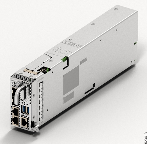
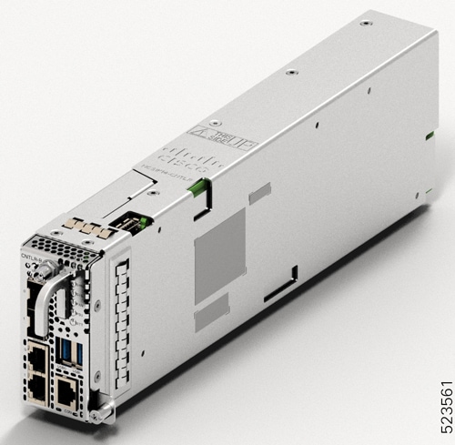
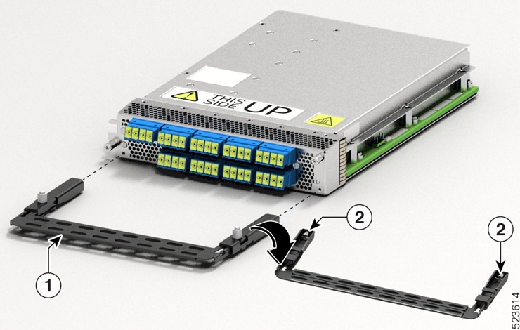
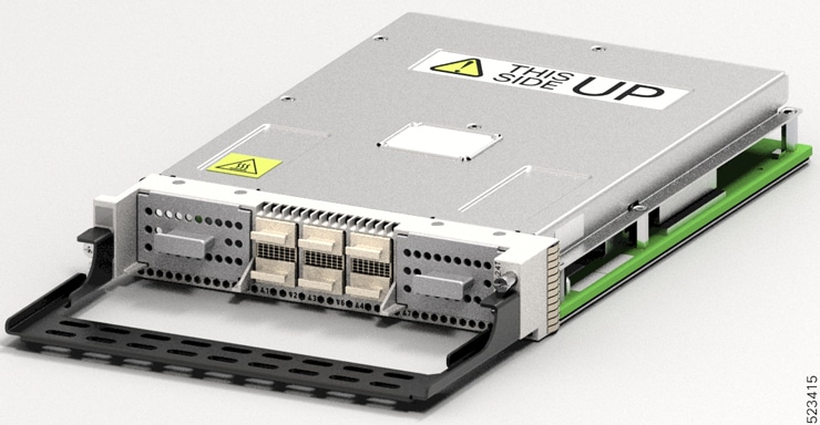
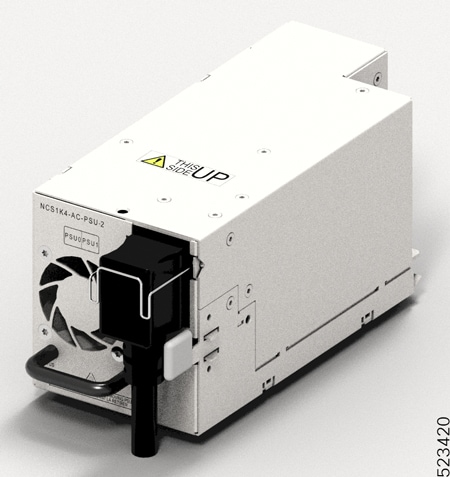
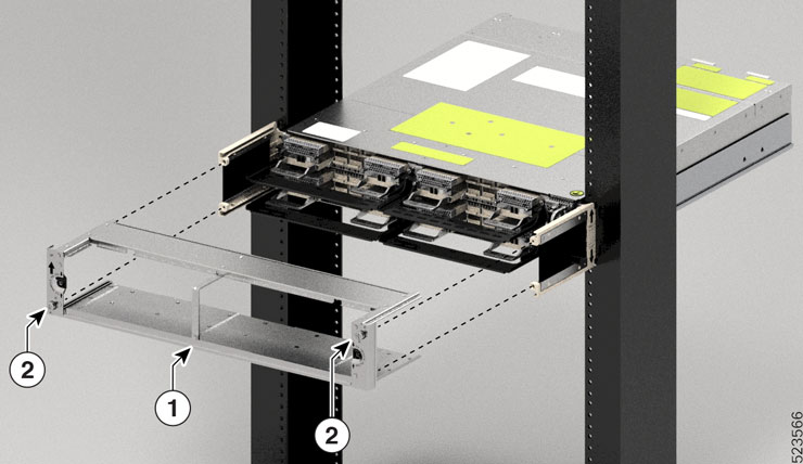
Before inserting the SSD into the slot, use the UP label to help you orient the module correctly.

Step 2

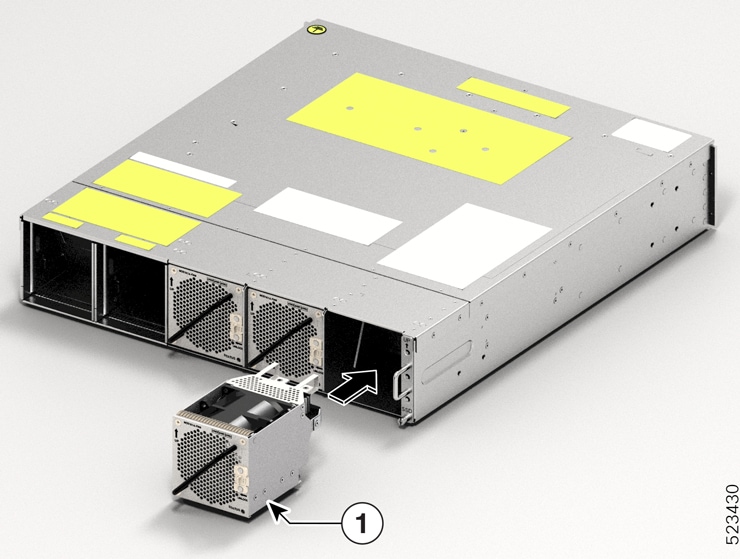
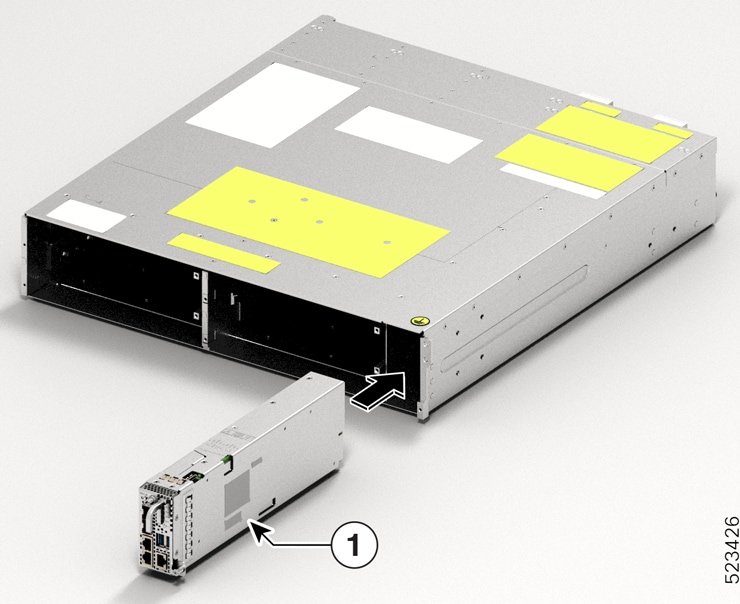
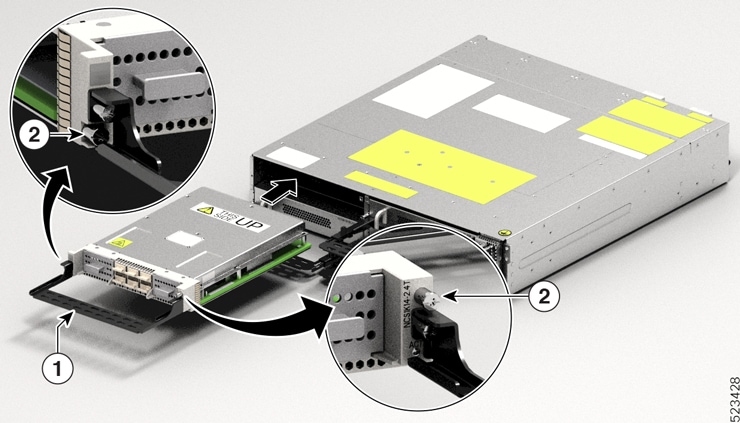
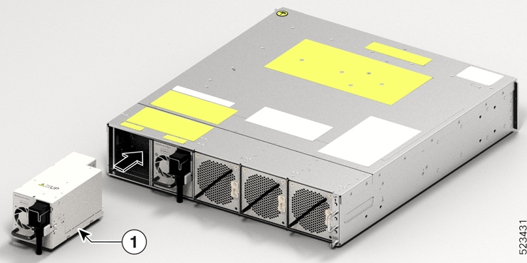
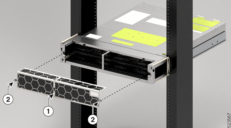
Grasp the front handle and slide the SSD into the slot.
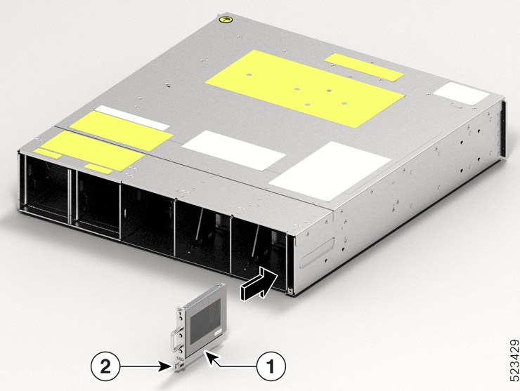
Figure 1. Installing the SSD
This image shows how to install the SSD in the Cisco NCS 1014 chassis.

Callout

Component

1

SSD

2

M3 T15 screw

Step 3

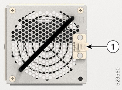
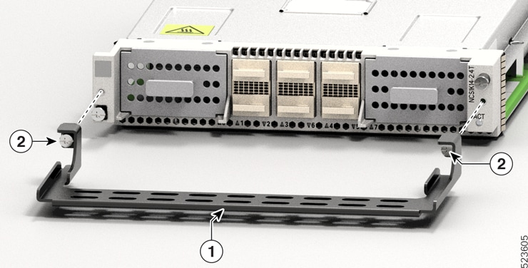
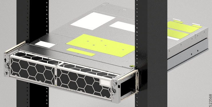
Using a T15 six lobe/slot screwdriver, tighten the lone captive screw to a torque value of 0.65 N-m (5.75 lbs-in).


Install the Fan Unit

Follow these steps to install the fan units into the Cisco NCS 1014 chassis.

Procedure


Step 1

Before inserting the fan unit, use the This Side Up label to help yourself orient the fan unit correctly.

Step 2

Use one hand to support the fan unit. Then use the other hand to hold the front handle and insert the fan unit in to the slot.

While inserting the fan unit, use your thumb to push the spring-loaded lever to the left and hold it in the unlock position.

Figure 2. Inserting a Fan Tray
This image shows the installation of a Fan Tray into the Cisco NCS 1014 chassis.

Callout

Component

1

Fan Tray

Step 3

Release the spring-loaded lever to lock the fan unit in its position.

Figure 3. Spring-loaded Lever in Released Condition
This image shows the spring-loaded lever in release condition in the fan unit.

Callout

Component

1

Sping-loaded lever

Step 4

Repeat the above steps until you complete installing all the fan units.


Install the Controller

Follow these steps to install the controller into the Cisco NCS 1014 chassis.

Procedure


Step 1

Before inserting the controller, use the This Side Up label to help yourself orient the controller correctly.

Figure 4. Perspective View of NCS1K14-CNTLR-K9 Controller
This image shows the perspective view of the controller.
Figure 5. Perspective View of NCS1K14-CNTLR-B-K9 Controller
This image shows the perspective view of the controller.

Step 2

Slide the controller into the slot. To slide the controller:

  1. With one hand, support the controller at the bottom.

  2. With the other hand, hold the front handle and push the controller into the slot.

Figure 6. Inserting the Controller
This image shows how to insert the controller into the Cisco NCS 1014 chassis.

Callout

Module

1

Cisco NCS 1014 Controller Card (NCS1K14-CNTLR-K9)

Step 3

Using a T15 Torx screwdriver, tighten the two M3 T15 Torx screws to a torque value of 0.65 N-m (5.75 lbs-in).


Attach the Fiber Management Bracket

Use this procedure to attach a fiber management bracket to a line card or filler card.

The fiber management brackets are available in the package. Each line card or filler card comes with its own fiber management bracket. Do not interchange the fiber management brackets. The CCMD-16-C, CCMD-16-L, and 1.2T cards have adjustable fiber management brackets. The 2.4T DWDM card has a fixed-length fiber management bracket.

Procedure


Step 1

Attach the fiber management bracket to the card (line card or filler card). To attach:

  1. Orient the captive screws in the fiber management bracket to the line card.

    Ensure that the fiber management bracket is in the correct orientation. Incorrect orientation obstructs accessibility to the ports.

  2. Seat the bracket captive screws in the line card screw holes.

Figure 7. Attaching the Fiber Management Brackets to the 2.4T Card
This image shows attaching the fiber management brackets to the 2.4T Card
Table 1. 2.4T Card Accessories

Callout

Accessory

1

Fiber management bracket

2

Captive screws

Step 2

Using a torque-limiting T15 Torx screwdriver, tighten the two M3 T15 Torx screws of the fiber management bracket to a torque value of 0.65 N-m (5.75 lbs-in).

We recommend that you do not remove the fiber management brackets after installing the line card into the chassis.

The subsequent section describes the procedure to adjust the length of the fiber management bracket.


Adjust the Fiber Management Bracket


Note


This procedure is not applicable for the 2.4T line card that has a fixed-length fiber management bracket. You can skip this procedure.


Use this task to adjust the length of the fiber management bracket of the following cards:

  • CCMD-16-C

  • CCMD-16-L

  • 1.2T

  • Filler card


Note


We recommend that you maintain the fiber management bracket in the shorter position for ETSI racks, to maintain a 600-mm footprint. We also recommend that you adjust the bracket length before installation.


Procedure


Step 1

Disengage the horizontal bar in the bracket. To do this, push down the plunger pins on both sides of the bracket.

Figure 8. Adjusting the Fiber Management Bracket
This image shows the adjustable fiber bracket for the NCS1K14-CCMD-16-C/L card.

1

Horizontal bar

2

Plunger pins

Step 2

Pull the horizontal bar of the fiber management bracket outwards to increase the length of the bracket.

The plunger pins lock the bracket when the horizontal bar is fully extended.

You can verify whether the plunger pins are locked based on the visibility of their grooves.

  • If both grooves are visible, the pins are disengaged.

  • If no groove is visible, the bar is in the transient stage.

  • If one groove is visible, the bar is correctly installed and locked.


Install the Line Card

Use this task to install a line card into the Cisco NCS 1014 chassis. The Cisco NCS 1014 chassis supports a maximum of four line cards.

Before you begin

It is mandatory to attach the fiber management brackets to the filler cards and line cards before you install the chassis onto a rack. For a detailed procedure, see Attach Fiber Management Bracket.


Note


The following procedure presumes that you ordered the Cisco NCS 1014 chassis preinstalled with filler cards only.

The following procedure also applies to filler cards installation.


Procedure


Step 1

Loosen the Torx screws of the filler card using a T15 Torx screwdriver.

Step 2

Holding the fiber management bracket of the filler card with one hand and supporting it with the other, pull the filler card from the chassis.

Step 3

Before inserting the line card into the slot, use the This Side Up label to help yourself orient the line card correctly.

Figure 9. Perspective View of NCS1K14-2.4T-K9 Line Card
This image shows the NCS1K14-2.4T-K9 line card in perspective view.

Step 4

Use both the hands while inserting a line card. To insert the line card, perform the following actions:

  1. Use one hand to support the bottom of the line card.

  2. Use the other hand to hold the fiber management bracket.

  3. With both hands, guide the line card into the slot.

Caution


Use the fiber management brackets only for pulling out or pushing in the line cards or filler cards. Do not use the fiber management brackets to carry the cards. Always support the line card and filler card at the bottom with your hand.

Step 5

Slide the line card completely inside, into the slide guide till it engages in the chassis.

Step 6

Using the torque-limiting T-15 six lobe/slot screwdriver, tighten the two captive screws of the line card to a torque value of 0.44 N-m (3.89 lbs-in) to secure the line card.

Figure 10. Inserting the NCS1K14-2.4T-K9 Line Card
This image shows how to insert the NCS1K14-2.4T-K9 line card into the Cisco NCS 1014 chassis.
Callout

Accessory

1

Use the fiber management bracket for holding the line card.

2

Captive screws


Install the Power Supply Units (PSUs)

Use this procedure to install the PSUs into the Cisco NCS 1014 chassis.

Procedure


Step 1

Orient the PSU correctly before inserting. Check for the This Side Up label.

Figure 11. Perspective View of NCS1K4-DC-PSU-2
This image shows the NCS1K4-DC-PSU-2 PSU in perspective view.
Figure 12. Perspective View of NCS1K4-AC-PSU-2
This image shows the NCS1K4-AC-PSU-2 PSU in perspective view.

Step 2

Slide the PSU into the slot as follows:

  1. Support the PSU at the bottom with one hand.

  2. Hold the handle with your other hand.

  3. Push the PSU in until you hear a click sound; see the following figure for direction of insertion.

    The click sound indicates that the unit has latched.

    Note

     
    Press and release the locking latch only for removing the PSU.
Figure 13. Inserting the PSU
This image shows how to insert the NCS 1004 PSU in perspective view.

1

PSU


Connect DC Power to the Cisco NCS 1014 Chassis


Caution


The Cisco NCS 1014 chassis relies on the protective devices in the building installation to protect against short circuit, overcurrent, and ground faults. Ensure that the protective devices comply with local and National Electrical Codes (NEC).


Figure 14. Rating Label for DC Power

Procedure


Step 1

Verify that the correct fuse panel is installed in the top mounting space.

Step 2

Measure and cut the cables as needed to reach the Cisco NCS 1014 chassis from the fuse panel.

Step 3

Dress the power according to local practice.

Step 4

Connect the office battery and return cables according to the fuse panel engineering specifications.

Step 5

Affix the power lug on the unit with two screws. Tighten the screws using torque of 2.7 N-m ± 0.3 N-m (21.69–28.09 lbs-in.).

Caution


Torque level greater than 3.0 N-m can damage the unit.

Use #6AWG cables. Ensure a minimum gap of 50 mm below the chassis for routing the cables. For ETSI racks, use 180-degree power lugs to maintain 600-mm footprint.

Figure 15. NCS1K4-DC-PSU-2 with 180-degree Power Lug Cable Connection
This image shows the NCS1K4-DC-PSU-2 PSU components

Callout

Component

Callout

Component

1

Status LED

4

Locking latch

2

PSU Handle

5

Protective cover

3

6AWG 180-degree exit cables

Step 6

Use protection covers to keep the lugs in place.

Snap fit the protection cover towards the top for 90-degree lugs and push it down for straight (180-degree) lugs.


Connect AC Power to the Cisco NCS 1014 Chassis


Caution


The Cisco NCS 1014 chassis relies on the protective devices in the building installation to protect against short circuit, overcurrent, and ground faults. Ensure that the protective devices comply with local and National Electrical Codes.


Figure 16. Rating Label for AC Power

The voltage rating value for AC power ranges either 200–240 or 100–127 V~ depending on the standards in various countries.


Note


You need a dual pole breaker for the installation. The rating of the dual pole breaker for each feed is 16 A for input voltage 200–240 V~, and 20 A for input voltage 100–127 V~.


Procedure


Step 1

Verify that the AC cable is installed in the correct AC source panel. Ensure that either the fuse is removed or the circuit breaker is in the off position and locked out.

Step 2

Attach the AC power cable to the cable connector in the AC power module.

Note


Ensure that there is a minimum gap of 50 mm for routing the cables. Use a 180-degree exit cable to maintain a footprint of 600 mm for ETSI racks.

Step 3

Close the cable retention clips to secure the power cables and to prevent their accidental removal.

Figure 17. NCS1K4-AC-PSU-2 with 180-Degree Cable Connection
This image shows the NCS1K4-AC-PSU-2 PSU components

Callout

Component

Callout

Component

1

Status LED

4

Locking latch

2

PSU Handle

5

Protective cover

3

6AWG 180-degree exit cable


Install the Pluggables

Use this task to install the pluggables on a line card. The line card ships with pluggable caps.


Caution


To protect the line card, insert pluggable caps into the pluggable slots when no pluggable is inserted.

Transceivers, fiber-optic cables, and optical ports on the line cards must stay clean and free of dust to maintain high signal accuracy and to prevent damage to the connectors. Cover them with pluggable cap when not in use.


Procedure


Step 1

Remove the pluggable caps.

You can retain and reuse the pluggable caps.

Step 2

Attach the optical fiber to the pluggables.

See the pluggable labels for Tx and Rx polarity to attach the optical fibers.

Step 3

Orient the pluggable to the correct slot.

For installing the CIM8 module in the 2.4T line card, use the fiber management bracket for navigation support.

Figure 18. Inserting the CIM8 Module in the 2.4T Card

Step 4

Insert the pluggables until the pluggables fully engage in their respective ports to ensure proper connection to the line card.

While inserting the CIM8 module, ensure that the screws are protruding out as much as possible.

Step 5

If you are installing the CIM8 module in the 2.4T line card, tighten the two captive screws to secure it in the port, else skip to the next step.

See the CIM8 module label for the correct torque to apply to tighten the screws. Use the T15 Torx screwdriver to tighten the CIM8 module. You must avoid extra torque application on the CIM8 screw. Excess application of torque can damage the screws. Only after both screws are tightened properly, the system detects the CIM8 pluggable. Even for the OIR of CIM8, you must be careful to avoid any damage to the CIM8 screws.

Step 6

Check whether you have installed all the required pluggables before routing the cables.

Step 7

Route the cables emerging from the pluggables over the fiber management bracket.

Guidelines for managing the fibers and cables:

  • Use Velcro tapes to tie the fibers to the fiber management bracket.

  • Fibers from the left line cards must exit from the left and fibers from the right line cards must exit from the right.

  • Fibers and cables from the controller must exit from the right. Maintain sufficient slack to extract the controller during online insertion and removal (OIR).

  • Cables from the PSU must exit from the left (when viewed from the rear side).

    Important


    For ETSI racks, route the 180-degree power cables in the 50-mm space below the chassis to maintain a chassis footprint of 600 mm.

  • Ground cable must exit from the right.

  • Rest the fibers exiting from the pluggables on the cable support bracket. Pass a Velcro tape in the gap provided in the cable support bracket to tie the fibers.


Install the Air Filter

Use this procedure to install the air filter. We recommend that you include the air filter installation as part of the chassis installation.

Precautions while installing air filters

  • Ensure that you have not installed the ground lug onto the chassis.

  • Ensure that the pull tabs of the pluggables do not get damaged during installation.

  • Ensure that the Velcro of the fiber management bracket does not interfere with the air filter.

  • To remove a chassis placed in the middle, in a stacked configuration, you must remove the air filters of the chassis above and below also to avoid accidental scratches on the surface of the chassis.

  • Ensure the cables from the controller exit from the right. Maintain sufficient slack to enable easy removal and insertion of the controller during online insertion and removal (OIR).

Procedure


Step 1

After inserting the chassis in the rack, fix the air filter side brackets on either side of the chassis using the following actions:

  1. Check for the arrow indications on the side of the brackets.

  2. Using the Phillips screws on either side, bind the chassis and the air filter side brackets to the rack.

  3. Tighten the Phillips screws (48-101524-01) using a number-2 Phillips screwdriver, to a torque value of 4.65 N-m (41 lbs-in).

Note


In case you are installing the air filter after you installed the chassis, then unscrew and remove the four screws on either side that bind the chassis to the rack. After fixing the air filter side brackets, you need only three screws on either side to bind the chassis and air filter side brackets to the rack.

Figure 19. Screws to Secure the Cisco NCS 1014 Chassis on to the Rack

Callout

Component

1

Torx screw

Figure 20. Installing the Air Filter Side Brackets
The image shows the fixing of the air filter side brackets to the NCS 1014.

Callout

Component

1

Air filter side brackets

2

Torx screws

Step 2

Install the ground lug. See Ground the Cisco NCS 1014 Chassis.

Remember


Install the ground lug before installing the air filter frame.

Step 3

Slide the air filter frame into the air filter side brackets.

Caution


Make sure that you tagged the air filter frame to a specific chassis and not mixed with other chassis.

Caution


Before placing the spare label on the air filter frame, verify that the serial number on the spare label matches with the serial number on top of the chassis. If the serial numbers do not match, there can be inconsistencies in inventory management.

Figure 21. Installing the Air Filter Frame
The image shows the installation of the Air filter frame on the front of the NCS 1014 chassis.

Callout

Component

1

Air filter frame

2

Captive screw

Step 4

Using a T15 Torx screwdriver, tighten the screw on either side (placed diagonally) to a torque value of 0.65 N-m (5.6 lbs-in).

Step 5

Orient the air filter correctly. The arrow must point upwards.

Figure 22. Installing the Air Filter

Callout

Component

1

Air filter arrow

2

Captive screws

Step 6

Push the air filter onto the frame and adjust so that it engages with the edges of the frame.

Step 7

Using a T15 Torx screwdriver, tighten the screw on either side of the air filter to a torque value of 0.65 N-m (5.6 lbs-in).

Figure 23. Installed Air Frame