Remove and Replace Cisco NCS 1014 Modules

This chapter describes the procedures to replace Cisco NCS 1014 modules.


Caution


All the modular slots in the NCS 1014 chassis should always be populated with respective modules (line-cards, controller, PSU & fan units). Empty line card slots to be populated with filler modules, which are shipped with the chassis. The replacement or upgrade of the modules (Online Insertion or Removal, OIR) to be performed only when the ambient temperature is below 30-degree C. The OIR of modules should be completed within five minutes to prevent overheating of the components.


Remove and Replace the Pluggables in the 2.4T Line Card

Use this procedure to remove and replace the pluggables in the 2.4T DWDM line card.


Note


This procedure is applicable to replacing pluggables in other line cards too.


Procedure


Step 1

Unfasten the Velcro tapes holding the fibers to the fiber management bracket and free up space to remove the required pluggable.

Step 2

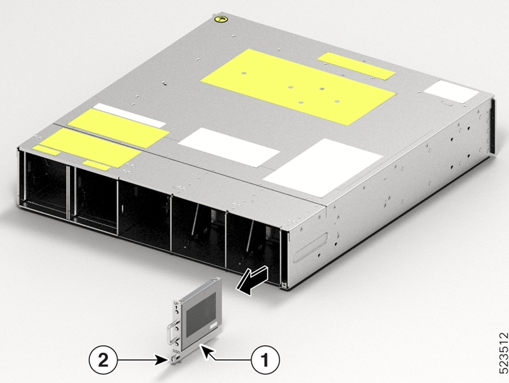
If you want to remove the CIM8 module, then loosen the two screws, else continue with the next step.

Step 3

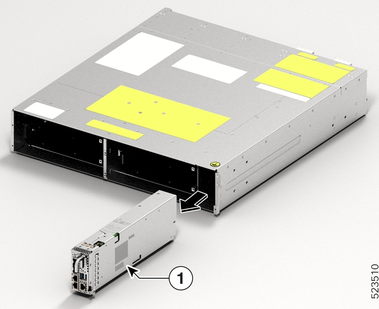
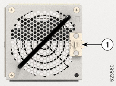
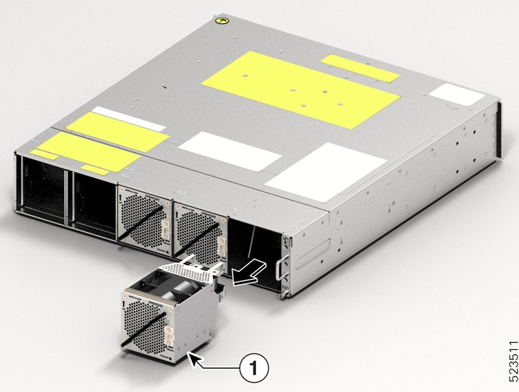
Use the pull tabs to pull out the required pluggable.

Step 4

Remove the fibers from the required pluggable.

Step 5

Repeat the previous steps until you complete removing all the required pluggables.

Step 6

(Optional) Insert pluggable caps into the pluggable slots when the slots have no pluggable.


What to do next

Install the Pluggables

Remove and Replace a Line Card

Use this procedure to remove and replace the line card or filler card in the Cisco NCS 1014 chassis.


Caution


Perform the removal and replacement procedure for a line card or filler card only when the ambient temperature is below 30℃ (80℉). Complete the procedure within five minutes to prevent overheating of the chassis components.


Procedure


Step 1

Using the T-15 six lobe/slot screwdriver, loosen the captive screws available in the line card.

Step 2

Holding the fiber management bracket with one hand and supporting the line card with the other, pull it from the slot.

Caution


Use the fiber management brackets only for pulling out or pushing in the line cards or filler cards. Do not use the fiber management brackets to carry the cards. Always support the line card or filler card at the bottom with your hand.


What to do next

Install the Line Card

Remove and Replace the Power Supply Unit (PSU)

Use this procedure to remove and replace a PSU in the Cisco NCS 1014 chassis.

Before you begin

Remove the connections to the power supply:

  • Disconnect power from the breaker before disconnecting power from the power supply unit.

  • Remove the cable retainers and the power cables, in case of an AC power supply unit.

  • Remove the protection covers, fasteners, and lugs, in case of a DC power supply unit.

Procedure


Step 1

Press the locking latch towards the left to release the lock.

Figure 1. Locking Latch on the DC PSU

1

Locking latch

Figure 2. Locking Latch on the AC PSU

1

Locking latch

Step 2

Holding the handle with one hand and supporting the PSU with the other, gently pull out the PSU from the slot.

Figure 3. Removing the PSU

What to do next

Install the Power Supply Units (PSUs).

Remove and Replace the Controller

Use this procedure to remove and replace the controller in the Cisco NCS 1014 chassis.

Procedure


Step 1

Using a T15 six lobe/slot screwdriver, unfasten the two screws on the controller.

Step 2

Holding the handle with one hand and supporting the controller with the other, gently pull the controller from the slot.

Figure 4. Removing the Controller

1

Controller Card


What to do next

Install Controller

Remove and Replace the Fan Module

Use this procedure to remove and replace a fan module in the Cisco NCS 1014 chassis.


Caution


Online insertion and removal (OIR) duration for the fan module at 30℃ ambient temperature is five minutes.


Procedure


Step 1

Push and hold the spring-loaded lever toward the left with your thumb (unlock position).

Figure 5. Spring-Loaded Lever in Holding or Unlock Position

1

Sping-loaded lever

Step 2

Holding the handle with one hand and supporting the fan module with the other hand, gently pull it out of the chassis.

Figure 6. Removing the Fan Module
This image shows the removal of the fan module from the NCS 1014 chassis.

1

Fan module


What to do next

Install Fan Module.

Remove and Replace the Solid State Drive (SSD)

Use this procedure to remove and replace the SSD in the Cisco NCS 1014 chassis.

Procedure


Step 1

Using a T15 six lobe/slot screwdriver, loosen the lone captive screw on the SSD.

Figure 7. Removing the SSD

Callout

Component

1

SSD

2

Captive screw

Step 2

Remove the SSD. To remove, gently pull out the SSD from the slot.


What to do next

Install the Solid State Drive (SSD)

Wipe Data in Disk Using Secure Erase

If the NCS 1014 unit becomes faulty and must be returned, contact Cisco TAC to open a Return Material Authorization (RMA) request. Before opening an RMA request, you can securely erase data in NCS 1014 disks using the Secure Erase feature.


Warning


Use this procedure only during RMA.


Before you begin

Take out the NCS 1014 unit that you planned for RMA out of the data center and the network. Access NCS 1014 only using the console port.

Procedure


Step 1

When NCS 1014 boots (power cycle), the following message appears.


Version 2.19.1266. Copyright (C) 2023 American Megatrends, Inc.                 
BIOS Date: 07/31/2023 14:01:08 Ver: 0ACHI0460                                    
Press <DEL> or <ESC> to enter setup.
Press DEL or ESC key to enter BIOS.

Press DEL or ESC key to enter BIOS.

Step 2

Select the Advanced tab using the arrow keys.

The disk security details such as HDD Secure Erase are displayed in the Advanced tab.

Step 3

Select HDD Secure Erase to securely erase data.

The list of SSDs that support Secure Erase is displayed. D:13 is CPU SSD and D:14 is Chassis SSD.

Step 4

Select the SSD from which you want to erase data using the arrow keys.

Step 5

Select Yes in the Confirmation screens.

The system proceeds to securely erase data in the selected SDD after these confirmations.