Cisco NCS 1014 Chassis Overview
The Cisco NCS 1014 chassis is an advanced multihaul optical platform supporting transponders and line system cards. It is a 2RU chassis that delivers a universal transponder solution which provides excellent performance for metro, long-haul and submarine applications.
Cisco NCS 1014 chassis has slots for the following modules:
-
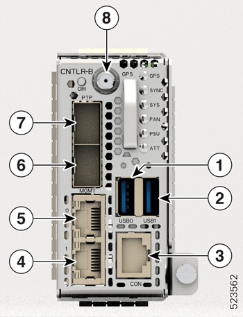
Removable controller
-
Removable backup solid state drive (SSD)
-
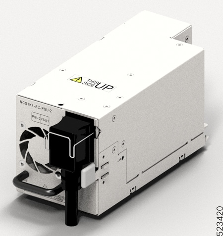
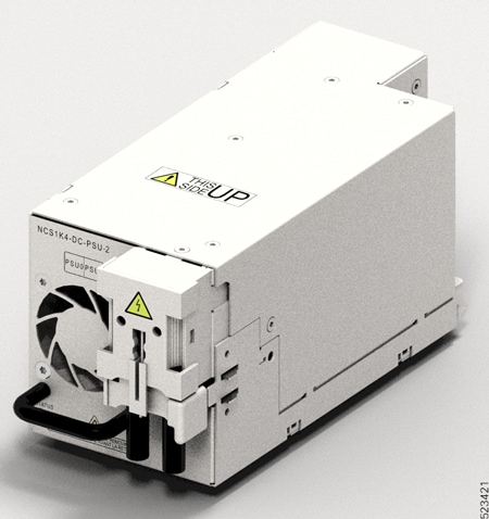
Two replaceable power supply units (PSU)
-
Three replaceable fan modules
-
Four line cards
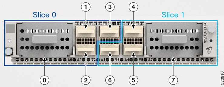
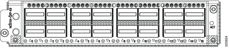
The Cisco NCS 1014 chassis supports the following line cards.
|
Line Card |
Description |
Release |
|---|---|---|
|
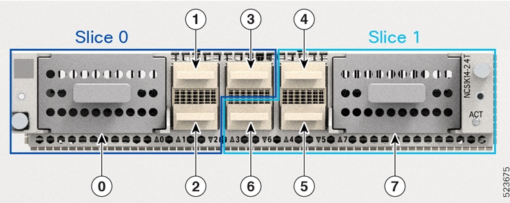
2.4T DWDM Transponder Card |
Cisco IOS XR Release 7.11.1 |
|
|
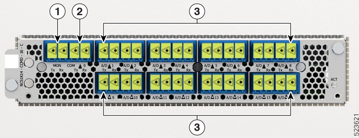
16-port Colorless Mux/Demux Optical Line Card, C-band |
Cisco IOS XR Release 7.11.1 |
|
|
16-port Colorless Mux/Demux Optical Line Card, L-band |
Cisco IOS XR Release 7.11.1 |
|
|
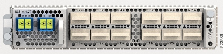
1.2T DWDM Transponder Card |
Cisco IOS XR Release 7.11.1 |
|
|
2.4TX DWDM Transponder Card |
Cisco IOS XR Release 24.1.1 |
|
|
3.2T DWDM Transponder Card |
Cisco IOS XR Release 24.1.1 |
The Cisco NCS 1014 chassis has two slots for field-replaceable AC and DC PSUs that support up to 2.5 kW per system and 580 W per line card slot.
For more information about the Cisco NCS 1014 chassis, see Cisco NCS 1014 datasheet.
 Note |
|
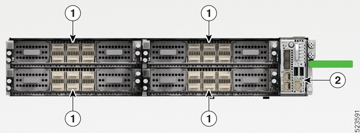
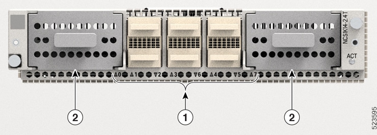
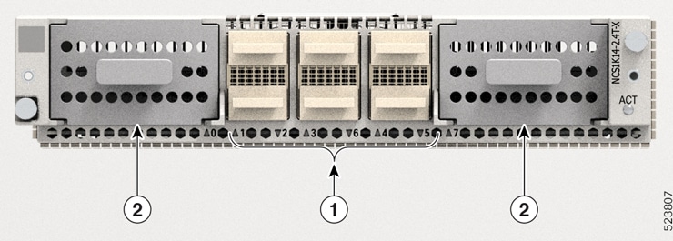
The controller is on the front side. The SSD, PSUs, and the fan modules are on the rear side of the chassis. You can insert the line cards into the four slots as shown in the following figure.
|
Callout |
Modules |
|---|---|
|
1 |
Line Cards |
|
2 |
Controller |
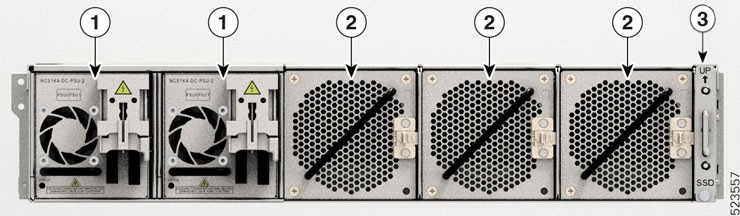
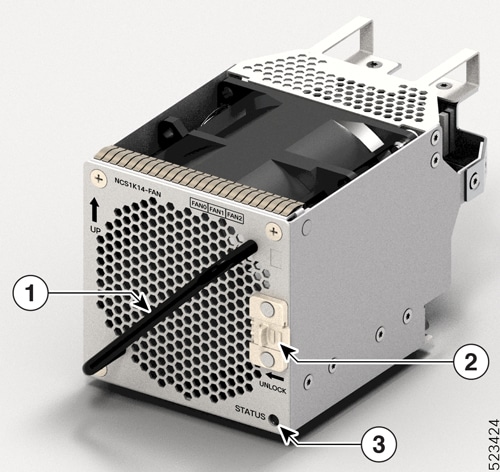
The following figure shows the PSUs, fan modules, and SSD installed in the chassis.
|
Callout |
Modules |
|---|---|
|
1 |
Power Supply Units (Slots 0 and 1) |
|
2 |
Fan Modules (Slots 0, 1, and 2) |
|
3 |
SSD |
You must install AC or DC PSUs as the power supply modules. The chassis does not allow mixed PSU configuration.
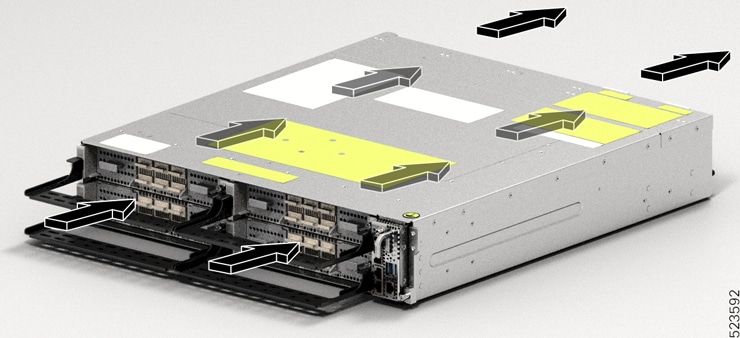
Airflow in the Cisco NCS 1014 Chassis
The Cisco NCS 1014 chassis has a front-to-back airflow scheme. The air inlet is at the front side of the chassis and the exhaust is on the rear side. The fan modules cool down the line cards. Ensure that no object obstructs or impedes the airflow as it can lead to reduced airflow in the system, causing components to operate at a higher temperature.
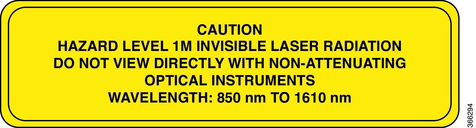
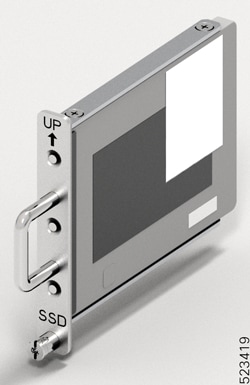
Class 1M Laser Product Label
The Class 1M Laser Product label is shown in the following figure.

Cooling System
The Cisco NCS 1014 cooling system actively regulates the chassis temperature using the three field-replaceable fan trays and the built-in fans within the PSU units. This system implements cooling in two different airflow paths:
-
Line Cards Cooling
The three fan modules enable cooling for the line cards. The software monitors the chassis temperature and adjusts the fan speed according to the ambient temperature range.
-
Controller Card Cooling
The internal fans within the two PSUs cool the controller card. If any critical alarms arise due to controller temperature, the software overrides the PSU fan speed.
Note
For normal operating conditions, the software does not control the PSU fans.
During the power cycle, each fan runs at maximum rotations per minute. After the chassis boots up, the fans return to their normal speed according to the ambient temperature.


 Feedback