Cisco Optical Site Manager Topology

This chapter describes the different Cisco Optical Site Manager views. In this chapter, you will also learn to add new racks.

Cisco Optical Site Manager Topology

The COSM Topology page offers two distinct views:
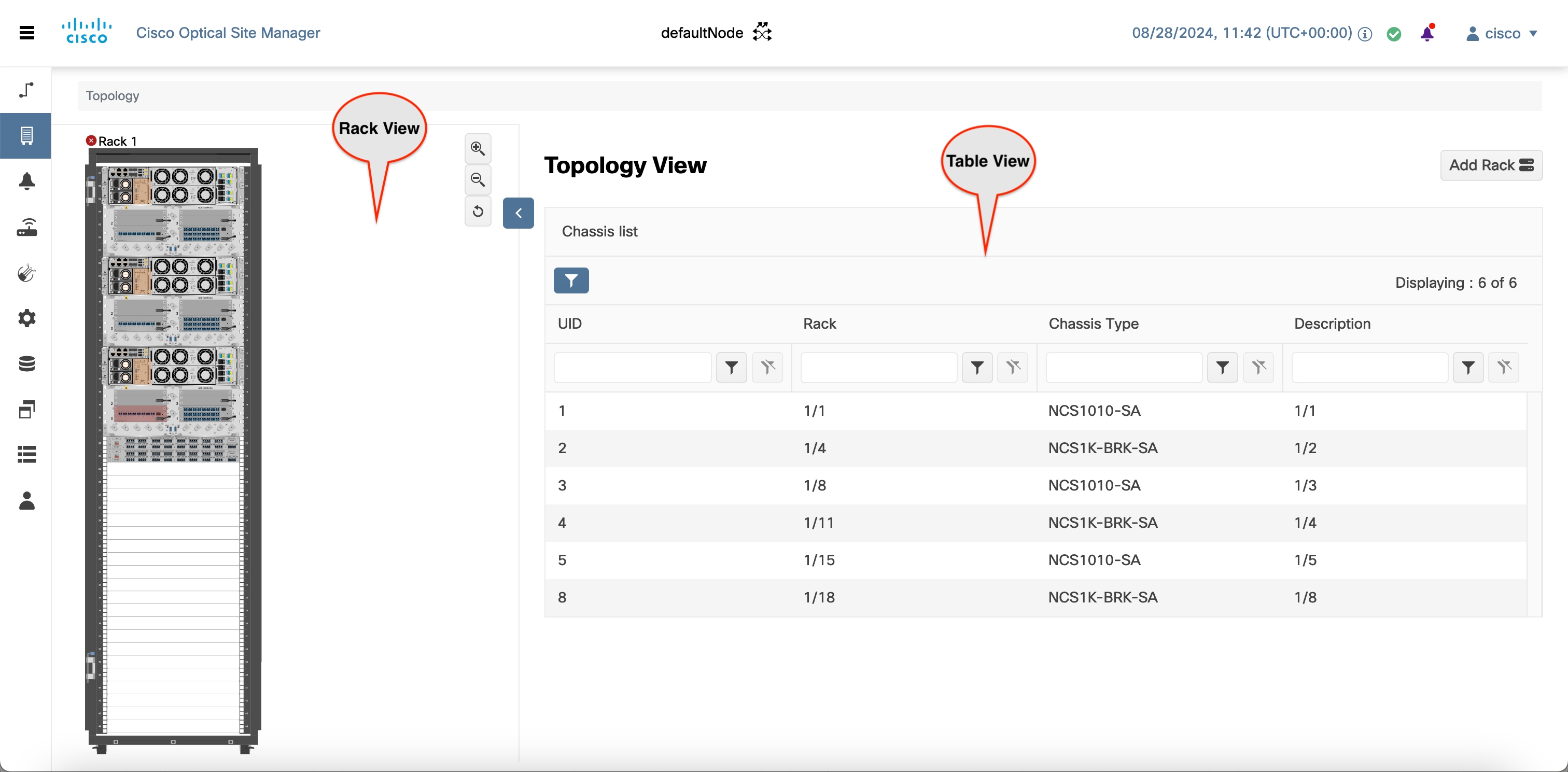
Rack View

The Rack view provides a visual representation of a rack, including its nodes and cards. Hovering over a device or node in this view displays the device's name as a tooltip.

Table View

The Table view displays the Chassis list along with details such as node UIDs, rack number, chassis type, and description. It also provides the option to add a new rack.

Figure 1. Cisco Optical Site Manager Topology

Create a Rack

Use this task to add a rack.

Before you begin

Log into Cisco Optical Site Manager

Procedure


Step 1

Click COSM Topology in the left panel.

The COSM Topology page appears.

Step 2

Click Add Rack.

The Add rack dialog box appears.

Step 3

Enter a rack ID in the Rack ID field.

You can enter any value from 1 through 32767.

Step 4

Click Apply.

The rack is added to the rack and table views.


Open the Card View

Use this task to open the card view.

Before you begin

Log into Cisco Optical Site Manager

Procedure


Step 1

Click COSM Topology in the left panel.

The Rack and Chassis view appear.

Step 2

Navigate to the chassis view using any one of the following steps:

  • Click the chassis icon in the logical view.

  • Click the ID in the Chassis List or the Chassis ID in the Cisco Optical Site Manager List in the tabular view.

  • Click the rack ID in the left panel to open the rack view and identify the chassis of interest.

  • Click the chassis name in the expanded rack tree view in the left panel.

Step 3

From the Rack view, right-click the slot that contains the card and choose Open Card.

The card view appears.


View Passive Device Details

Use this task to view a passive device to a passive chassis. You can also use this task to identify a specific passive device that is associated to a USB port by using the LED blink function.

Before you begin

Procedure


Step 1

Click COSM Topology in the left panel.

Step 2

Click the rack name in the Rack view.

Step 3

Click the Provisioning tab.

Step 4

Click Passives to expand the section.

The passive devices are displayed in the table.

Step 5

Select the check box corresponding to a device and click Edit.

The USB Port field for the selected device becomes editable.

Step 6

Select the USB port from the drop-down list.

Step 7

Click Apply.

Step 8

(Optional) Click LED Blink to start blinking the LED of the passive device.

Step 9

(Optional) Click LED Status to know the LED status of the associated device.

Step 10

(Optional) Click LED Blink again to stop the blinking.


View Voltage, Temperature and Current Information

Use this task to display the voltage, temperature and current information of a chassis.

Before you begin

Log into Cisco Optical Site Manager

Procedure


Step 1

Click COSM Topology in the left panel.

The COSM Topology page appears.

Step 2

Click the rack name from the Rack view.

Step 3

Right-click the outer edge of the chassis from the Rack view and select Open to open the Chassis view.

Alternatively, you can also double-click the chassis to open the Chassis view.

The Chassis view appears.

Step 4

Click the Provisioning tab.

Step 5

Click the Voltage/Temperature/Current section to expand it.

Expand the Voltage, Temperature, and Current sections to view the voltage , temperature, and current information of the chassis.

View Power Monitoring Parameters

Use this task to display the power monitoring parameters of a chassis.

Before you begin

Log into Cisco Optical Site Manager

Procedure


Step 1

Click COSM Topology in the left panel.

The COSM Topology page appears.

Step 2

Click the rack name from the Rack view.

Step 3

Right-click the chassis from the Rack view and select Open.

Alternatively, you can also double-click the chassis to open the Chassis view.

The Chassis view appears.

Step 4

Click the Provisioning tab.

Step 5

Click the Power Monitor section to expand it.

The Power Monitor section displays the environment type, power summary, voltage thresholds of the chassis.