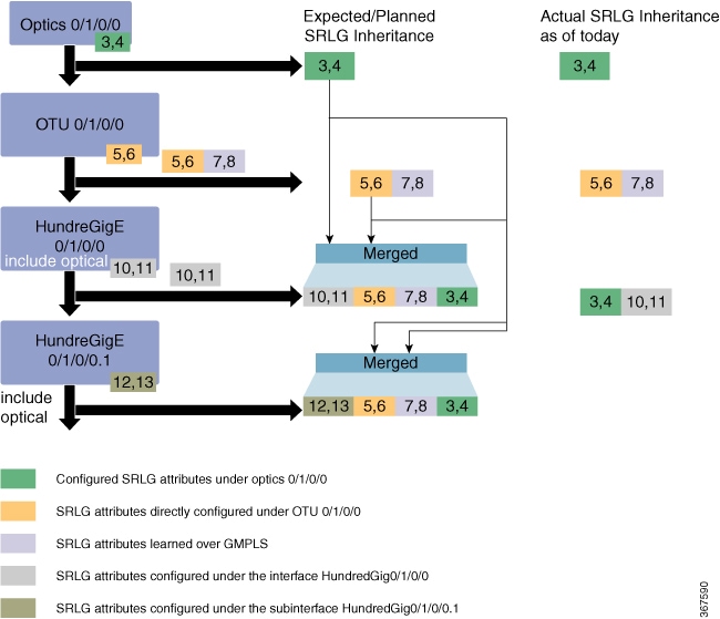
To provide better protection at L2 layer, the SRLG configured on OTN layer needs to be propagated to the Ethernet Terminated
Interface. SRLG Announce feature enables to fetch SRLG values from all traversed TE-Links, summarize and announce them to
the ethernet terminated interface at head and tail nodes.
Perform following
procedure to enable SRLG announce on Ethernet Terminated ODU on headend node.
SRLG announce can be enabled on both headend and tailend.
Enabling SRLG
Announce on Ethernet Terminated ODU
The following
example shows how to enable SRLG Announce on ethernet terminated ODU using
Cisco IOS XR commands:
RP/0/RP0:hostname# configure
RP/0/RP0:hostname(config)# mpls traffic-eng
RP/0/RP0:hostname(config-mpls-te)# gmpls optical-nni
RP/0/RP0:hostname(config-te-gmpls-nni)# controller odu-group-te 10
RP/0/RP0:hostname(config-te-gmpls-tun-0xa)# signalled-bandwidth ODU2
RP/0/RP0:hostname(config-te-gmpls-tun-0xa)# static-uni local-termination interface-name TenGigE0/1/0/0/100 remote-termination unnumbered 32
RP/0/RP0:hostname(config-te-gmpls-tun-0xa)# destination ipv4 unnumbered 10.77.132.185 interface-if index 19
RP/0/RP0:hostname(config-te-gmpls-tun-0xa)# announce-srlg
RP/0/RP0:hostname(config-te-gmpls-tun-0xa)# path-option 1 dynamic protected-by none lockdown
To verify the above configuration use the following show command:
 RP/0/RP0:hostname# show mpls tr tunnels detail

Name: Odu-Group-Te11  Destination: 10.77.132.185  Ifhandle:0x82001e4
  Signalled-Name: 3M_otn11
  Status:
    Admin:    up Oper:   up   Path:  valid   Signalling: connected

    path option 1, (LOCKDOWN) type dynamic  (Basis for Current, path weight 1)
      Protected-by PO index: none
        Reroute pending (DROP)
    Bandwidth Requested: 10037273 kbps  CT0
    Creation Time: Thu Oct  5 08:59:53 2017 (00:45:09 ago)
  Config Parameters:
    Bandwidth: ODU2
    Priority: 24  0 Affinity: 0x0/0xffff
    Metric Type: TE (default)
    Path Selection:
      Tiebreaker: Min-fill (default)
    Hop-limit: disabled
    Cost-limit: disabled
    Path-invalidation timeout: 10000 msec (default), Action: Tear (default)
    AutoRoute: disabled  LockDown:  enabled  Policy class: not set
    Forward class: 0 (default)
    Forwarding-Adjacency: disabled
    Autoroute Destinations: 0
    Loadshare:          0 equal loadshares
    Auto-bw: disabled
    Fast Reroute: Disabled, Protection Desired: None
    BFD Fast Detection: Disabled
    Reoptimization after affinity failure: Enabled
    Soft Preemption: Disabled
  SNMP Index: 72
  Binding SID: None
  Static-uni Info:
    Locally Terminated Interface Name: TenGigE0_1_0_0_200  Ifhandle: 0x82001fc
      Local Termination Type: Ether
      State: Terminated up since Thu Oct  5 08:59:54 2017
      SRLG Values: 2,  7,  8,  20,  21,  33,
  Remote termination Interface: 0.0.0.0 [42]
    Egress Client Port: 0.0.0.0 [42]
  Working Homepath ERO:
    Status: Down
    Explicit Route:
  Diversity Info: None

  History:
    Tunnel has been up for: 00:45:04 (since Thu Oct 05 08:59:58 UTC 2017)
    Current LSP:
      Uptime: 00:45:08 (since Thu Oct 05 08:59:54 UTC 2017)
  Current LSP Info:
    Instance: 302, Signaling Area: OSPF OTN area 0
    Uptime: 00:45:08 (since Thu Oct 05 08:59:54 UTC 2017), Signaling State: Up, Oper State: Up
    G-PID: Gfp_F Generic Framing Procedure-Framed (54)
      XC Id: 0
      State: Connected
      Uptime: Thu Oct  5 08:59:54 2017
      Egress Interface: OTU40/1/0/0 (State:Up  Ifhandle:0x8a0020c)
      Egress Controller: ODU40_1_0_0 (State:Up Ifhandle:0x8a00214)
      Egress Sub Controller: ODU20_1_0_0_42 (State:Up, Ifhandle:0x82001ec)
      Path Ingress  label: TPN: 4 BitMap Len: 80 BitMap: 25:32
      Resv Egress  label: TPN: 4 BitMap Len: 80 BitMap: 25:32
    Router-IDs: local      10.77.132.187
                downstream 10.77.132.185
    Soft Preemption: None
    SRLGs: mandatory collection
    Path Info:
      Outgoing:
        Explicit Route:
          Strict, 10.77.132.185(19)
          Strict, 10.77.132.185
          Strict, 10.77.132.185(42)

      Record Route: Empty
      Tspec: signal_type ODU2 Bitrate 0kbps NVC 0 MT 1

      Session Attributes: Local Prot: Not Set, Node Prot: Not Set, BW Prot: Not Set
                          Soft Preemption Desired: Not Set
    Path Protection Info:
      SNC Mode:SNC-N TCM id:Not used Type:Bi-directional APS
      Path Protection Profile Type: 1+0
      Bits S:0 P:0 N:0 O:0
      Timeout WTR:0 milliseconds HoldOff:0 milliseconds
    Resv Info:
      Record Route:
        IPv4 10.77.132.185, flags 0x20 (Node-ID)
        Label         Label TPN: 4 BitMap Len: 80 BitMap: 25:32 , flags 0x1

        Unnumbered 10.77.132.185 (19), flags 0x0
        Label         Label TPN: 4 BitMap Len: 80 BitMap: 25:32 , flags 0x1
      Fspec: signal_type ODU2 Bitrate 0kbps NVC 0 MT 1

  Persistent Forwarding Statistics:
    Out Bytes: 0
    Out Packets: 0
Displayed 2 (of 2) heads, 0 (of 0) midpoints, 0 (of 0) tails
Displayed 2 up, 0 down, 0 recovering, 0 recovered heads
 Feedback