Bidirectional Forwarding Detection

This chapter includes details for Bidirectional Forwarding Detection (BFD).

BFD is a detection protocol designed to provide fast forwarding path failure detection times for all media types, encapsulations, topologies, and routing protocols. In addition to fast forwarding path failure detection, BFD provides a consistent failure detection method for network administrators.

Bidirectional Forwarding Detection

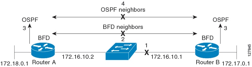
Bidirectional forwarding detection (BFD) provides low-overhead, short-duration detection of failures in the path between adjacent forwarding engines. BFD allows a single mechanism to be used for failure detection over any media and at any protocol layer, with a wide range of detection times and overhead. The fast detection of failures provides immediate reaction to failure in the event of a failed link or neighbor.

Prerequisites for Implementing BFD

You must be in a user group associated with a task group that includes the proper task IDs. The command reference guides include the task IDs required for each command. If you suspect user group assignment is preventing you from using a command, contact your AAA administrator for assistance.

The following prerequisites are required to implement BFD:

  • Interior Gateway Protocol (IGP) is activated on the router if you are using IS-IS or OSPF.

  • To enable BFD for a neighbor, the neighbor router must support BFD.

Restrictions for Implementing BFD

These restrictions apply to BFD:

  • Demand mode is not supported.

  • Asynchronous echo mode is not supported.

  • Mutli hop BFD is not supported.

  • BFD for bundles is not supported.

Operating Modes for BFD

BFD can operate in two modes, Asynchronous mode and Demand mode. Cisco NCS 4000 supports the asynchronous mode only. In this mode, the systems periodically send BFD control packets to one another. If a number of those packets in a row, are not received by the other system, the session is declared to be down.

When BFD is running asynchronously, the following happens:

  • Each system periodically sends BFD control packets to one another. Packets sent by BFD router “Peer A” to BFD router “Peer B” have a source address from Peer A and a destination address for Peer B.

  • Control packet streams are independent of each other and do not work in a request/response model.

  • If a number of packets in a row are not received by the other system, the session is declared down.

Figure 1. BFD Asynchronous Mode

Control packet failure in asynchronous mode (without echo), is detected using the values of the minimum interval (bfd minimum-interval ) and multiplier (bfd multiplier ) commands. For control packet failure detection, the local multiplier value is sent to the neighbor. A failure detection timer is started based on (I x M), where I is the negotiated interval, and M is the multiplier provided by the remote end. Whenever a valid control packet is received from the neighbor, the failure detection timer is reset. If a valid control packet is not received from the neighbor within the time period (I x M), then the failure detection timer is triggered, and the neighbor is declared down.

Table 1. BFD Packet Intervals

Configured Async Control Packet Interval (ms)

Multiplier value (the default is 3; range is from 2 to 50)

Async Control Packet Failure Detection Time (ms) (Interval X Multiplier)

The multiplier value is set to the default value of 3

3.3 (rounded off to 3)

3

9

10

3

30

20

3

60

50

3

150

100

3

300

1000

3

3000

2000 (this value is the default value)

3

6000

BFD for IPv4

Cisco NCS 4000 supports single hop BFD for IPv4.

BFD asynchronous packets are transmitted over UDP and IPv4 using source port 49152 and destination port 3784. For asynchronous mode, the source address of the IP packet is the local interface address, and the destination address is the remote interface address.

BFD is supported for connections over the following interface types:

  • Gigabit Ethernet (GigE)

  • Ten Gigabit Ethernet (10GigE)

  • Hundred Gigabit Ethernet (100GigE)

BFD Dampening

Bidirectional Forwarding Detection (BFD) is a mechanism used by routing protocols to quickly realize and communicate the reachability failures to their neighbors. When BFD detects a reachability status change of a client, its neighbors are notified immediately. Sometimes it might be critical to minimize changes in routing tables so as not to impact convergence, in case of a micro failure. An unstable link that flaps excessively can cause other devices in the network to consume substantial processing resources, and that can cause routing protocols to lose synchronization with the state of the flapping link.

The BFD dampening feature introduces a configurable exponential delay mechanism. This mechanism is designed to suppress the excessive effect of remote node reachability events flapping with BFD. The BFD Dampening feature allows the network operator to automatically dampen a given BFD session to prevent excessive notification to BFD clients, thus preventing unnecessary instability in the network. Dampening the notification to a BFD client suppresses BFD notification until the time the session under monitoring stops flapping and becomes stable.

Implementing BFD

By sending rapid failure detection notices to the routing protocols in the local router to initiate the routing table recalculation process, BFD contributes to greatly reduced overall network convergence time.

The figure below, shows a simple network with two routers running OSPF and BFD. When OSPF discovers a neighbor (1) it sends a request to the local BFD process to initiate a BFD neighbor session with the OSPF neighbor router (2). The BFD neighbor session with the OSPF neighbor router is established (3).

Figure 2. BFD process - establishing a connection

The figure below, shows what happens when a failure occurs on the network (1). The BFD neighbor session with the OSPF neighbor router is not reachable (2). BFD notifies the local OSPF process that the BFD neighbor is no longer reachable (3). The local OSPF process deletes the OSPF neighbor relationship (4). If an alternative path is available the routers will immediately start converging on it.

Figure 3. BFD process - failure detection

BFD over Bundle

Table 2. Feature History

Feature Name

Release Information

Feature Description

Bidirectional Forwarding Detection (BFD) over Link Aggregation Group (LAG)

Cisco IOS XR Release 6.5.31

BFD allows you to detect network failures between neighbors. Two modes are supported:

  • BFD over Bundle (BoB) - Standards-based fast failure detection of non-VLAN interfaces in LAG.

  • BFD over Logical Bundle - Standards-based fast failure detection of VLAN interfaces in LAG.

Commands added:

  • interface Bundle-Ether

  • bfd address-family

  • bfd mode

  • bundle minimum-active

  • encapsulation dot1q

  • bfd fast-detect

  • bfd minimum-interval

  • bfd multiplier

BFD over Bundle (BoB) mode is a standard based fast failure detection of Link Aggregation Group (LAG) member links. BoB supports only IETF standard for each bundle.


Note


The BFD client is bundlemgr for BFD over Bundle. Hence if BFD session goes down, bundlemgr brings down the bundle, and this in turn brings down the routing session.


Restrictions

  • To support BFD on bundle member links, ensure that the routers on either end of the bundle are connected back-to-back without a Layer 2 switch in between.

  • Do not configure the BoB and BFD over Logical Bundle (BLB) features simultaneously on the same bundle.

Enabling BFD Sessions on Bundle Members

This procedure describes how to enable BFD sessions on bundle member links.

Procedure


Step 1

configure

Step 2

interface Bundle-Ether bundle-id

Example:

RP/0/RP0:hostname(config)# interface Bundle-Ether 1

Enters interface configuration mode for the specified bundle ID.

Step 3

bfd address-family ipv4 fast-detect

Example:

RP/0/RP0:hostname(config-if)# bfd address-family ipv4 fast-detect

Enables IPv4 BFD sessions on bundle member links.

Step 4

bfd mode ietf

Example:

RP/0/RP0:hostname(config-if)# bfd mode ietf

Enables IETF mode for BFD over bundle for the specified bundle.

Step 5

commit


Specifying the BFD Destination Address on a Bundle

This procedure describes how to specify the BFD destination address on a bundle.

Procedure


Step 1

configure

Step 2

interface Bundle-Ether bundle-id

Example:

RP/0/RP0:hostname(config)# interface Bundle-Ether 1

Enters interface configuration mode for the specified bundle ID.

Step 3

bfd address-family ipv4 destination ip-address

Example:

RP/0/RP0:hostname(config-if)# bfd address-family ipv4 destination 10.20.20.1

Specifies the primary IPv4 address assigned to the bundle interface on a connected remote system, where ip-address is the 32-bit IP address in dotted-decimal format (A.B.C.D).

Step 4

commit


Configuring the Minimum Thresholds to Maintain an Active Bundle

The bundle manager uses two configurable minimum thresholds to determine whether a bundle can be brought up or remain up, or is down, based on the state of its member links.

  • Minimum active number of links

  • Minimum active bandwidth available

Whenever the state of a member changes, the bundle manager determines whether the number of active members or available bandwidth is less than the minimum. If so, then the bundle is placed, or remains, in DOWN state. Once the number of active links or available bandwidth reaches one of the minimum thresholds, then the bundle returns to the UP state.

This procedure describes how to configure minimum bundle thresholds.

Procedure


Step 1

configure

Step 2

interface Bundle-Ether bundle-id

Example:

RP/0/RP0:hostname(config)# interface Bundle-Ether 1

Enters interface configuration mode for the specified bundle ID.

Step 3

bundle minimum-active bandwidth kbps

Example:

RP/0/RP0:hostname(config-if)# bundle minimum-active bandwidth 580000

Sets the minimum amount of bandwidth required before a bundle can be brought up or remain up. The range is from 1 through a number that varies depending on the platform and the bundle type.

Step 4

bundle minimum-active links links

Example:

RP/0/RP0:hostname(config-if)# bundle minimum-active links 2

Sets the number of active links required before a bundle can be brought up or remain up. The range is from 1 to 16.

Step 5

commit


Configuring BFD Packet Transmission Intervals and Failure Detection Times on a Bundle

BFD asynchronous packet intervals and failure detection times for BFD sessions on bundle member links are configured using a combination of the bfd address-family ipv4 minimum-interval and bfd address-family ipv4 multiplier interface configuration commands on a bundle.

BFD asynchronous packet intervals and failure detection times for BFD sessions on bundle member links are configured using a combination of the bfd address-family ipv4 minimum-interval and bfd address-family ipv4 multiplier interface configuration commands on a bundle.

This procedure describes how to configure the minimum transmission interval and failure detection times for BFD asynchronous mode control packets on bundle member links.

Procedure


Step 1

configure

Step 2

interface Bundle-Ether bundle-id

Example:

RP/0/RP0:hostname(config)# interface Bundle-Ether 1

Enters interface configuration mode for the specified bundle ID.

Step 3

bfd address-family ipv4 minimum-interval milliseconds

Example:

RP/0/RP0:hostname(config-if)# bfd address-family ipv4 minimum-interval 2000

Specifies the minimum interval, in milliseconds, for asynchronous mode control packets on IPv4 BFD sessions on bundle member links. The range is from 4 to 30000.

Step 4

bfd address-family ipv4 multiplier multiplier

Example:

RP/0/RP0:hostname(config-if)# bfd address-family ipv4 multiplier 3

Specifies a number that is used as a multiplier with the minimum interval to determine BFD control packet failure detection times and transmission intervals for IPv4 BFD sessions on bundle member links. We recommend to have multiplier value of 3.

Step 5

commit


Enabling IETF Mode for BFD over Bundle

This procedure describes how to enable IETF mode for BFD over bundle.

Procedure


Step 1

configure

Step 2

interface Bundle-Ether bundle-id

Example:

RP/0/RP0:hostname(config)# interface Bundle-Ether 1

Enters interface configuration mode for the specified bundle ID.

Step 3

bfd mode ietf

Example:

RP/0/RP0:hostname(config-if)# bfd mode ietf

Enables IETF mode for BFD over bundle for the specified bundle.

Step 4

bfd address-family ipv4 fast-detect

Example:

RP/0/RP0:hostname(config-if)# bfd address-family ipv4 fast-detect

Enables IPv4 BFD sessions on the specified bundle.

Step 5

commit


Running Configuration

This section shows a sample of BFD over bundle configuration.

R1:


interface FortyGigE0/2/0/2
bundle id 1 mode active
!

interface bundle-ether1
ipv4 address 172.31.13.6 255.255.255.252
bfd address-family ipv4 multiplier 3
bfd address-family ipv4 destination 172.31.13.5
bfd address-family ipv4 fast-detect
bfd address-family ipv4 minimum-interval 200
!

R2:


interface FortyGigE0/2/0/2
bundle id 1 mode active

interface Bundle-Ether1
ipv4 address 172.31.13.5 255.255.255.252
bfd address-family ipv4 multiplier 3
bfd address-family ipv4 destination 172.31.13.6  
bfd address-family ipv4 fast-detect
bfd address-family ipv4 minimum-interval 200

BFD over Logical Bundle

Bidirectional Forwarding Detection (BFD) over Logical Bundle (BLB) feature implements and deploys BFD over bundle VLAN interfaces.

BLB feature is different from the BFD over Bundle (BoB) feature which runs on non-VLAN bundle interfaces. These two features are distinct from each other. Do not configure these two features simultaneously on the same bundle.


Note


Routing protocols are BFD clients for the BLB feature. Hence if BFD session goes down, it will bring down the routing session. The default timer is 50 milliseconds.


Restrictions

  • BLB sessions are restricted to an interval of 300 milliseconds and a multiplier of 3. Though you can configure more aggressive parameters, Cisco does not recommend it.

  • Do not configure the BLB and BFD over Bundle (BoB) features simultaneously on the same bundle.

Creating VLAN Sub-interface under Bundle Interface

This procedure describes how to create VLAN sub-interface under the bundle interface.

Procedure


Step 1

configure

Step 2

interface Bundle-Ether bundle-id

Example:

RP/0/RP0:hostname(config)# interface Bundle-Ether 1

Enters interface configuration mode for the specified bundle ID.

Step 3

ipv4 address ip-address subnet-mask

Example:

RP/0/RP0:hostname(config-if)# ipv4 address 10.1.1.1 255.255.255.0

Specifies IP address and subnet mask.

Step 4

encapsulation dot1q vlan-id

Example:

RP/0/RP0:hostname(config-if)# encapsulation dot1q 1

Defines the matching criteria to map 802.1Q frames ingress on an interface to the appropriate service instance.

Step 5

commit


Enable BFD for OSPF on an Interface

This procedure describes how to enable BFD for Open Shortest Path First (OSPF) on an interface. The steps in this procedure are applicable to IS-IS as well. In case of IS-IS, the command mode is different.

Procedure


Step 1

configure

Step 2

router ospf process-name

Example:

RP/0/RP0:hostname(config)# router ospf 10

Enters the OSPF configuration mode. For the IS-IS routing protocol, use the router isis command.

Step 3

area area-id

Example:

RP/0/RP0:hostname(config)# area 10

Configures an OSPF area . This command is not applicable to IS-IS.

Step 4

interface type location

Example:

RP/0/RP0:hostname(config-ospf)# interface Bundle-Ether 1

Enters the interface configuration mode and specifies the interface for BFD configuration.

Step 5

bfd fast-detect

Example:

RP/0/RP0:hostname(config-ospf-if)# bfd fast-detect 

Enables BFD to detect failures in the path between adjacent forwarding engines. For IS-IS, use the bfd fast-detect ipv4 command.

Step 6

bfd minimum-interval milliseconds

Example:

RP/0/RP0:hostname(config-ospf-if)# bfd minimum-interval 100

Sets the minimum control packet interval for the BFD sessions. The supported BFD minimum-interval timer value is 100 ms.

Step 7

bfd multiplier value

Example:

RP/0/RP0:hostname(config-ospf-if)# bfd multiplier 3

Sets the BFD multipler value. The default value is 3. We recommend to have a multiplier value of 3.

Step 8

commit


Enabling BFD on a BGP Neighbor

This procedure describes how to enable BFD on a BGP per neighbor, or per interface.

Table 3. Feature History

Feature Name

Release Information

Description

BFD on BGP

Cisco IOS XR Release 6.5.33

Bidirectional Forwarding Detection (BFD) is now enabled on the Broad Gateway Protocol (BGP). BFD provides a single, standardized link/device/protocol failure detection method at any protocol layer and over any media. This feature offers quick failure detection between BGP nodes, allowing faster traffic rerouting to an alternate path.


Note


BFD neighbor router configuration is available for BGP only.


Note


BFD strict mode is not supported.


Procedure


Step 1

configure

Step 2

router bgp autonomous-system-number

Example:

RP/0/RP0:hostname(config)#router bgp 1

Enters BGP configuration mode, allowing you to configure the BGP routing process, use the show bgp command in EXEC mode to obtain the autonomous-system-number for the current router.

Step 3

neighbor ip-address

Example:

RP/0/RP0:hostname(config-bgp)#neighbor 192.0.2.2

Places the router in neighbor configuration mode for BGP routing and configures the neighbor IP address as a BGP peer.

This example configures the IP address 192.0.2.2 as a BGP peer.

Step 4

remote-as autonomous-system-number

Example:

RP/0/RP0:hostname(config-bgp-nbr)#remote-as 1

Creates a neighbor and assigns it a remote autonomous system.

This example configures the remote autonomous system to be 1.

Step 5

bfd multiplier multiplier

Example:

RP/0/RP0:hostname(config-bgp)#bfd multipier 3

Sets the BFD multiplier.

Step 6

bfd minimum-interval milliseconds

Example:

RP/0/RP0:hostname(config-bgp)#bfd minimum-interval 20

Sets the BFD minimum interval. Range is 4-30000 milliseconds.

Step 7

bfd fast-detect autonomous-system-number

Example:

RP/0/RP0:hostname(config-bgp-nbr)#bfd fast-detect

Enables BFD between the local networking devices and the neighbor whose IP address you configured to be a BGP peer in step 3.

In Step 3, the IP address 192.0.2.2 was configured as the BGP peer. In this example, BFD is enabled between the local networking devices and the neighbor 192.0.2.2.

Step 8

update-source interface-type interface-number

Example:

RP/0/RP0:hostname(config-bgp-nbr)#update-source hundredgige0/4/0/5.1

It checks routing sources to ensure that the incoming routing update's source IP address is on the same network as the interface receiving the update.

Step 9

address-family ipv4[ unicast|multicast]

Example:

RP/0/RP0:hostname(config-bgp-nbr)#address-family ipv4 labeled unicast

The address-family ipv4 declares neighbors with whom you want to exchange normal "IPv4 unicast" routes.

Step 10

route-reflector-client

Example:

RP/0/RP0:hostname(config-bgp-nbr)#route-reflector-client

It provides the unique BGP capability of republishing routes learned from an internal peer to other internal peers.

Step 11

next-hop-self

Example:

RP/0/RP0:hostname(config-bgp-nbr)#next-hop-self

It disables the next hop calculation for this neighbor.

Step 12

commit

Saves the configuration changes and remains within the configuration session.


Configuring a Line Card to Host BLB Sessions

The BLB sessions and bundle member links need not be configured on the same line card.

Procedure


Step 1

configure

Step 2

bfd

Example:

RP/0/RP0:hostname(config)# bfd

Enters BFD configuration mode.

Step 3

multipath include location location

Example:

RP/0/RP0:hostname(config-bfd)# multipath include location 0/2/CPU0

Defines the line card to host BLB and BFD multihop sessions.

Step 4

commit


Running Configuration

This section shows a sample of BFD over logical bundle configuration.

R1:


interface GigabitEthernet0/1/0/6
bundle id 200 mode active
 
interface GigabitEthernet0/1/0/7
bundle id 200 mode active
 
interface GigabitEthernet0/1/0/8
bundle id 200 mode active
 
interface Bundle-Ether200.10
ipv4 address 172.31.13.5 255.255.255.252
encapsulation dot1q 10
!
!
 
bfd
multipath include location 0/2/CPU0
!
 
router ospf 100
area 0
  interface Bundle-Ether200.10
    bfd minimum-interval 100
    bfd fast-detect
    bfd multiplier 3
  !
!
!

R2:


interface GigabitEthernet0/0/0/36
bundle id 200 mode active
 
interface GigabitEthernet0/0/0/37
bundle id 200 mode active
 
interface GigabitEthernet0/0/0/39
bundle id 200 mode active
 
interface Bundle-Ether200.10
ipv4 address 172.31.13.6 255.255.255.252
encapsulation dot1q 10
!
 
bfd
multipath include location 0/0/CPU0
!
 
router ospf 100
area 0
  interface Bundle-Ether200.10
   bfd minimum-interval 100
   bfd fast-detect
   bfd multiplier 3
  !
!
!