Remove and Replace the Cisco NCS 1020 Modules

This chapter describes the tasks to remove and replace Cisco NCS 1020 modules.


Note


In this chapter, "front fan tray" refers to the NCS1010-FAN tray, "rear fan tray" refers to the NCS1020-FAN tray, and "filler fan tray" refers to the NCS1020-FAN-BLANK tray. Front fan trays and rear fan trays contain a different set of fan units. Slots for the front fan trays and rear fan trays are not interchangeable.


Note


In this chapter, "Type 1 line card" refers to "NCS 1010 line card" and "Type 2 line card" refers to "NCS 1014 line card".


Caution


Always populate the modular slots in the Cisco NCS 1020 chassis with respective modules (line card, controller, PSU, and fan trays). Perform the replacement or upgrade of the modules (Online Insertion or Removal (OIR)) only when the ambient temperature is below 30-degree C. Complete the OIR of modules within five minutes to prevent overheating of the components.


Warning


This unit might have more than one power supply connection. To reduce risk of electric shock, remove all connections to de-energize the unit. Statement 1028.


Warning


There are no serviceable parts inside. To avoid risk of electric shock, do not open. Statement 1073


Warning


An instructed person is someone who has been instructed and trained by a skilled person and takes the necessary precautions when working with equipment. Statement 1089.

A skilled person or qualified personnel is someone who has training or experience in the equipment technology and understands potential hazards when working with equipment. Statement 1089


Warning


Only a skilled person should be allowed to install, replace, or service this equipment. See statement 1089 for the definition of a skilled person. Statement 1090


Warning


Only an instructed person or skilled person should be allowed to install, replace, or service this equipment. See statement 1089 for the definition of an instructed or skilled person. Statement 1091


Note


The maximum operating altitude for OIR is 1800 m.


Remove the L-Band Cover

Use this task to remove the L-band cover from the Type 1 line cards.
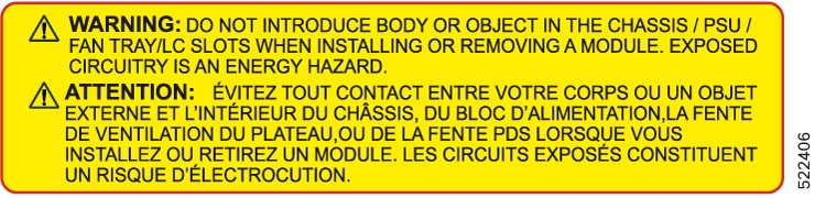

Caution


When upgrading the existing C-band only networks to C+L band networks, perform this procedure during the maintenance window only.


Procedure


Step 1

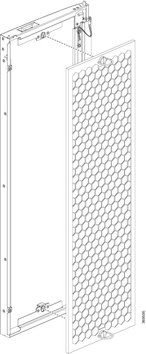
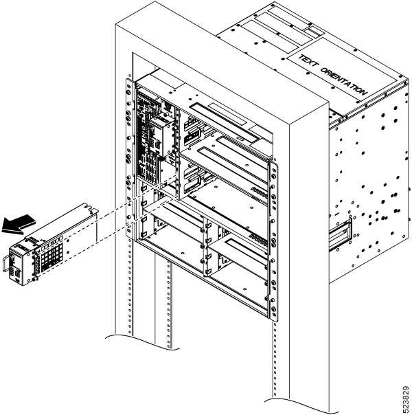
Look for the DO NOT USE label to locate the L-band cover.

Step 2

Using your fingers, hold the L-band cover on both sides.

Step 3

Holding the hinge surface on the left side of the cover, slowly pull the surface away from the chassis.

Figure 1. L-Band Cover

1

L-band hinge

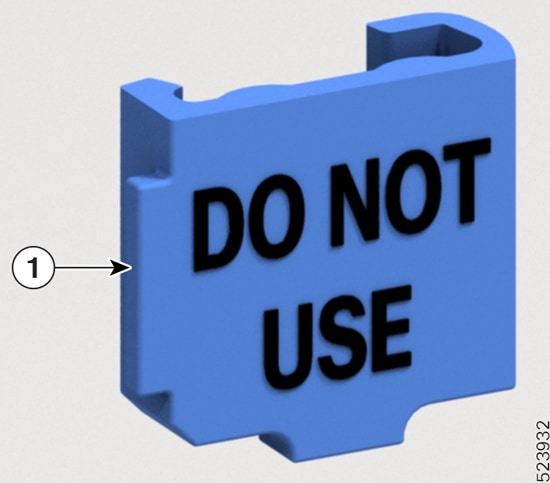
The cover pulls the L-band shutter along with it.

Step 4

(Optional) Using the other hand, prevent the L-band shutter from opening.

Step 5

Carefully rotate the L-band cover with the shutter above the hinge. This unlocks the cover from the shutter, then remove the L-band cover underneath the hinge area.
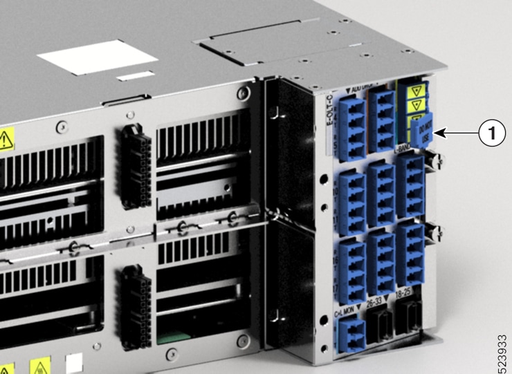
Figure 2. Removing L-Band Cover

1

L-band cover

Step 6

Discard the cover as per the local recycle practices.


Remove and Replace the Rear Fan Tray

Use this procedure to remove and replace the rear fan tray in the Cisco NCS 1020 chassis.


Note


The following procedure also applies to the filler fan tray removal.

Procedure


Step 1

Loosen the captive screws (one on the left side and the other on the right side) using a screwdriver.

Step 2

Holding the handle with one hand and supporting the fan tray with the other hand, gently pull it out of the chassis.

Figure 3. Removal of the Rear Fan Tray

What to do next

To install new fan trays or filler trays, see Install the Rear Fan/Filler Fan Trays

Remove and Replace the Power Supply Unit (PSU)

Use this procedure to remove and replace a PSU in the Cisco NCS 1020 chassis.

Before you begin

Remove the connections to the power supply:

  • Disconnect power from the breaker before disconnecting power from the power supply unit.

  • Rotate the retainer to unsecure the cables and pull the cables outward, in case of an AC power supply unit.

  • Remove the protection covers, fasteners, and lugs, in case of a DC power supply unit.

Procedure


Step 1

Press the locking latch towards the left to release the lock.

Step 2

Holding the handle with one hand and supporting the PSU with the other, gently pull out the PSU from the slot.

Figure 4. Removal of the AC PSU
Figure 5. Removal of the DC PSU

What to do next

Install the Power Supply Units (PSUs).

Remove and Replace the Solid State Drive (SSD)

Use this procedure to remove and replace the SSD in the Cisco NCS 1020 chassis.

Procedure


Step 1

Using a T15 six lobe/slot screwdriver, loosen the lone captive screw on the SSD.

Step 2

Rotate the ejector outward against a hinge point on the chassis to unmount it from the connector and then pull out.

Figure 6. Removing the SSD

What to do next

Install the Solid State Drive (SSD)

Remove and Replace the Type 2 Line Card

Use this procedure to remove and replace the type 2 line card in the Cisco NCS 1020 chassis.


Note


This procedure also applies to the type 2 filler card removal.

Caution


Perform the removal and replacement procedure for a type 2 line card or filler card only when the ambient temperature is below 30-degree C (80-degree F). Complete the procedure within five minutes to prevent overheating of the chassis components.


Procedure


Step 1

Using the T-15 six lobe/slot screwdriver, loosen the captive screws available in the type 2 line card.

Step 2

Holding the fiber management bracket with one hand and supporting the type 2 line card with the other, pull it away from the slot.

Caution


Use the fiber management brackets only for pulling out or pushing in the type 2 line cards or filler cards. Do not use the fiber management brackets to carry the cards. Always support the type line card or filler card at the bottom with your hand.


What to do next

Install the Type 2 Line/Filler Card

Remove and Replace Chassis Door Foam Air Filters

The air filter removes dust from the fan that is drawn into the chassis by the fan trays. If the air filters are damaged, dirty, or clogged with dust, replace them with new air filters. Failure to replace a compromised air filter can result in insufficient fan circulation through the chassis and temperature-related environmental alarms.


Note


First inspection of the air filter must be performed six months after the first installation of the air filter. Air filters must be inspected every three months after the initial six-month inspection and replaced if found to be dirty. Do not reuse the cleaned air filters. Replace them with a new air filter. We recommend having spare air filters in stock.


The front doors come with preinstalled air filters (NCS1020-DR-FTF=). If air filters need a replacement, use this procedure.

Procedure


Step 1

Remove the two quarter turn fasteners from the front door.

Figure 7. Replace Air Filter

Step 2

Install the new door filters on both the front doors.

Step 3

Tighten the two quarter turn fasteners back on the doors.

Step 4

Store the door frames in a package.


Remove and Replace the Front Fan Tray

Use this procedure to remove and replace a front fan tray in the Cisco NCS 1020 chassis.


Caution


Online Insertion and Removal (OIR) duration for the fan tray unit at 30-degree C (80-degree F) ambient temperature, is five minutes.

Only one fan tray should be removed at a time. Removing both fan trays simultaneously leads to overheating and may result in an unexpected system shutdown.


Procedure


Step 1

Loosen the captive screws (one on the left side and the other on the right side) using a screwdriver.

Step 2

Using the handle, pull the fan tray out of the chassis.

Figure 8. Removing the Front Fan Tray

Step 3

Repeat Step 1 and Step 2 to remove the second fan tray.


What to do next

To replace a front fan tray, see Install the Front Fan Trays.

Remove and Replace the Type 1 Line Card


Note


This procedure also applies to the type 1 active and passive filler card removal.

Use this procedure to remove and replace the type 1 line card in the Cisco NCS 1020 chassis.

Before you begin


Caution


  • Perform the removal and replacement procedure for the line card only when the ambient temperature is below 30-degree C and complete it within five minutes to prevent overheating of the chassis components.

  • Ensure that you perform the removal and replacement of the fan trays and line card within the five minutes of time limit.

  • As the fan trays draw power through the line card, you must complete the line card replacement before installing the fan trays on top of it.


Procedure


Step 1

Loosen the captive screws available in the type 1 card handles.

Step 2

Pull the handles out of the type 1 line card, and gently remove the card from the chassis.

Caution


Use the handles only to push and pull out the type 1 line card from the chassis. Do not use the handles to carry the type 1 line card. To prevent any accidental drop, support the top and bottom of the type 1 line card with your hand while you remove or insert it.

Figure 9. Removing the C-Band Type 1 Line Card

What to do next

To replace the type 1 line card, see Install the Type 1 Line/Filler Card.

Wipe Data in Disk Using Secure Erase

When NCS 1020 becomes faulty, contact TAC to open a Return Material Authorization (RMA) request. Before opening an RMA request, you can securely erase data on NCS 1020 disks using the Secure Erase feature.


Warning


Use this procedure only during RMA.


Before you begin

  • The NCS 1020 unit that is planned for RMA must be taken out of the data center and the network. You must access NCS 1020 only using the console port.

  • You must perform the RP cold reload for the successful CPU disk wipe.

  • You must perform the chassis cold reload for the successful Chassis disk wipe.

Procedure


Step 1

When NCS 1020 boots during RP cold reload or chassis cold reload, the following message appears.


Version 2.19.1266. Copyright (C) 2024 American Megatrends, Inc.                 
BIOS Date: 03/15/2024 16:30:21 Ver: 0ACHI0520                                   
Press <DEL> or <ESC> to enter setup.                                            
Entering Setup...

Press DEL or ESC key to enter BIOS.

Step 2

Select the Advanced tab using the arrow keys.

The disk security details such as HDD Secure Erase are displayed in the Advanced tab.

Step 3

Select HDD Secure Erase to securely erase data.

Step 4

Select the SSD using the arrow keys.

  1. Select the SSD under D: 13 for RP SSD erase.

  2. Select the SSD under D: 14 for chassis SSD erase.

Step 5

Click Yes on the Warning message box to erase the selected SSD data.


Remove and Replace the Controller

Use this procedure to remove and replace the controller in the Cisco NCS 1020 chassis.


Note


The following procedure also applies to controller filler removal in slot 1.

Procedure


Step 1

Using a screwdriver, unfasten the two captive screws on the controller.

Step 2

Pull out the handle from the controller.

Note


Controller filler has a fixed handle. You can skip this step.

Step 3

Holding the handle with one hand and supporting the controller with the other, gently remove the controller from the slot.

Figure 10. Removing the Controller

What to do next

To replace the controller or controller filler, see Install the Controller/Controller Filler.