Cisco NCS 1020 Overview

This chapter provides an overview for the Cisco NCS 1020 chassis, its modules, and line cards.


Note


This equipment is designed to boot up in less than 30 minutes, depending on its neighboring devices be fully up and running.


Cisco NCS 1020 Chassis Overview

The Cisco NCS 1020 is a new Wavelength Division Multiplexing (WDM) System that is optimized for ZR/ZR+ WDM router interfaces. Its salient features are:

  • Operates as an integrated optical layer Reconfigurable Optical Add-Drop Multiplexer (ROADM) and Amplifier system to support Point-to-Point (P2P), Ring, and Mesh network architectures, complete with add/drop capabilities.

  • Offers transmission versatility by supporting multiple coherent sources such as:

    • 400G digital coherent ZR/ZR+ optics (-10dBm output power)

    • High-performance DCO transponders such as 1.2T and 2-QDD-C cards that use high GBaud rates.

  • Supports C-band only and C+L-band WDM transmission to maximize capacity.


    Note


    In R24.2.11, the Cisco NCS 1020 supports only C-band networks.


Cisco NCS 1020 is a 10RU chassis that has an in-built External Interface Timing Unit (EITU) and the following field-replaceable modules.

  • One Solid State Drive (SSD)

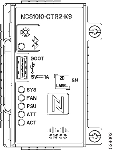
  • Two controllers (active and backup)

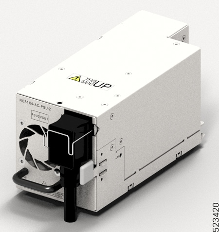
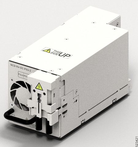
  • Two power supply units (PSUs)

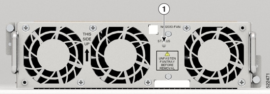
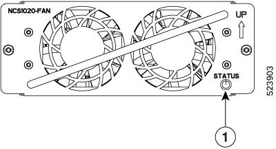
  • Eight fan trays (four NCS1010-FAN trays and four NCS1020-FAN trays)


    Note


    In this chapter, "front fan tray" refers to the NCS1010-FAN tray, "rear fan tray" refers to the NCS1020-FAN tray, and "filler fan tray" refers to the NCS1020-FAN-BLANK tray. Front fan trays and rear fan trays contain a different set of fan units. Slots for the front fan trays and rear fan trays aren’t interchangeable.
  • Ten line cards (two NCS 1010 line cards and eight NCS 1014 line cards).


    Note


    NCS 1010 line card slots and NCS 1014 line card slots aren’t interchangeable. In this chapter, Type 1 line card refers to "NCS 1010 line card" and Type 2 line card refers to "NCS 1014 line card".

The NCS 1020 chassis supports the following line cards:

Table 1. Supported Line Cards

Line Card

Description

Release

Type 1 Line Cards

NCS1K-OLT-C

C-band Optical Line Terminal without Raman

Cisco IOS XR Release 24.2.11

NCS1K-E-OLT-C

C-band Optical Line Terminal without Raman, Enhanced

Cisco IOS XR Release 24.2.11

Type 2 Line Card

NCS1K14-CCMD-16-C

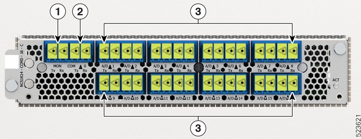
NCS 1000 16-port Colorless Direct attach LC with EDFA, C-band

Cisco IOS XR Release 24.2.11

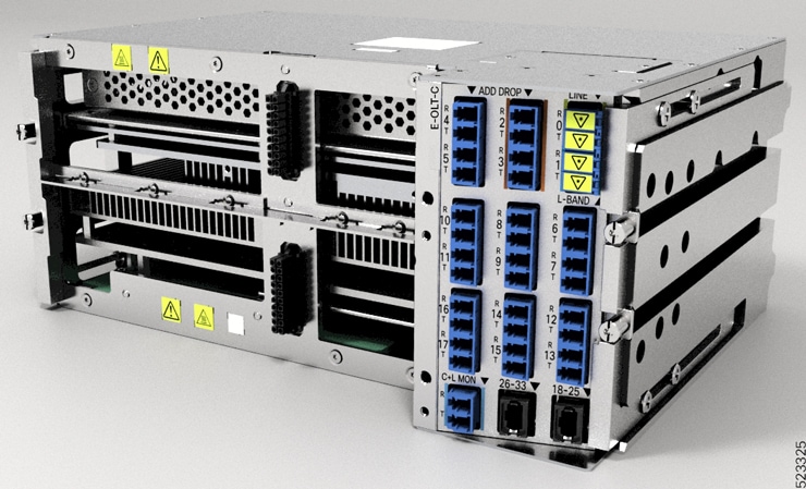
In this chapter, the following table lists the references that are used for each line card.

Line Card

Referred As

NCS1K-OLT-C=

OLT-C

NCS1K-E-OLT-C=

E-OLT-C

NCS1K14-CCMD-16-C=

CCMD-16-C

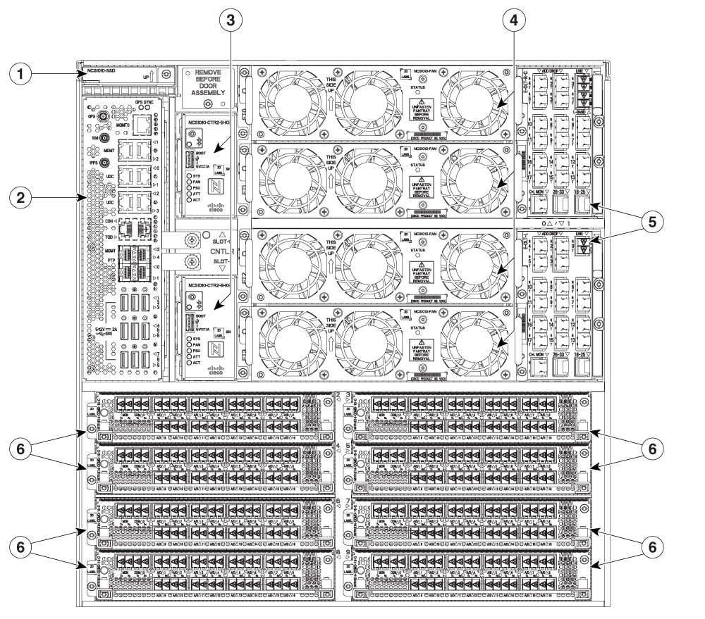
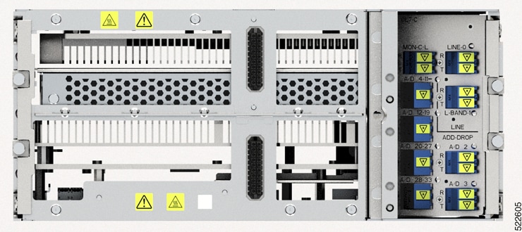
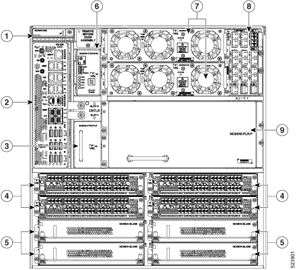
The chassis has the EITU, controller, SSD, front fan trays, and line card slots on the front side.

The following image shows a fully loaded Cisco NCS 1020 chassis. The chassis supports the Type 1 line cards in slots 0 and 1 and the Type 2 line cards in slots 2 to 9. The controllers occupy CNTLR slots 0 and 1.

Figure 1. Fully Loaded Cisco NCS 1020 Front View

1

SSD

4

Front fan trays

2

EITU

5

Type 1 line cards

3

Controllers

6

Type 2 line cards

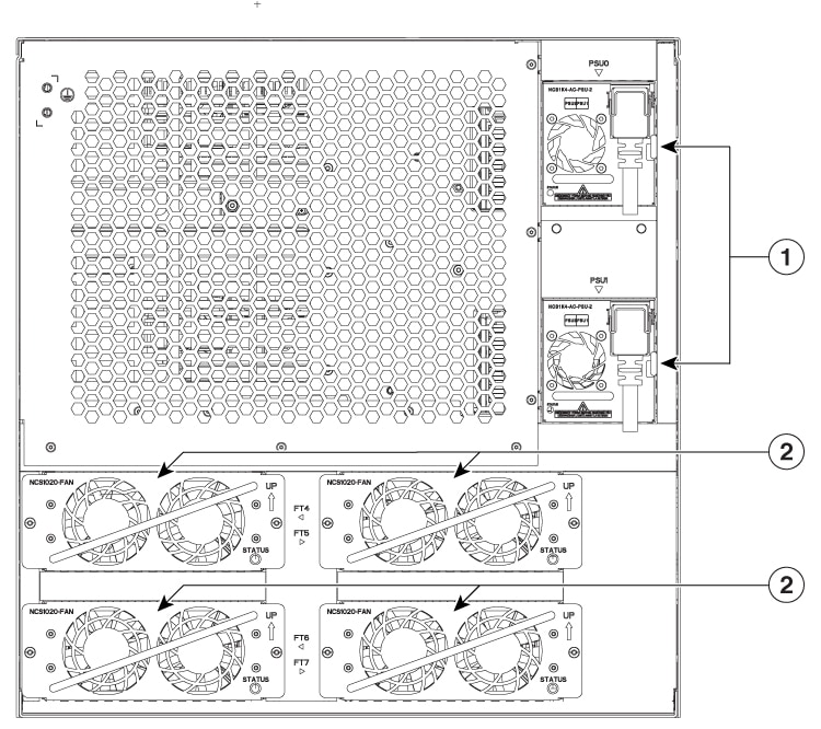
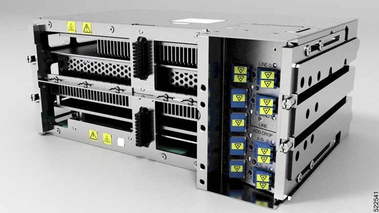
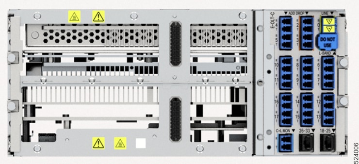
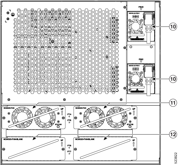
The chassis has the PSUs and rear fan trays on the rear side.

The following image is the rear view of the Cisco NCS 1020. In the chassis, the rear fan trays in the slots FT4 and FT5 cool the Type 2 line cards in slots from 2 to 5 at the front. Fan trays in slots FT6 and FT7 cool the Type 2 line cards in slots from 6 to 9 at the front.


Note


Filler fan trays can only be used when all the Type 2 card slots at the front are populated with Type 2 filler cards. Even if there’s only one Type 2 line card in the Type 2 card slots, you must install rear fan trays in both the rear slots. For more information, see Install the Rear Fan/Filler Fan Trays.


Figure 2. Cisco NCS 1020 Chassis Rear View

1

PSUs

2

Rear fan trays

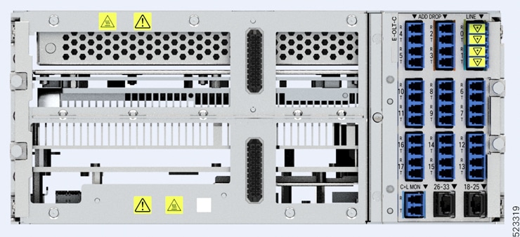
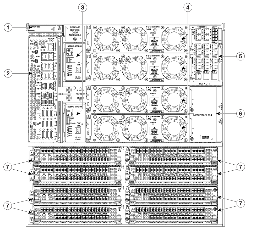
Airflow in the Cisco NCS 1020 Chassis

The Cisco NCS 1020 chassis has a front-to-rear airflow mechanism to ventilate the modules. It delivers cooling through five different channels.

The following image shows the airflow channels in a fully loaded NCS 1020 chassis.

Figure 3. Cisco NCS 1020 Chassis Airflow

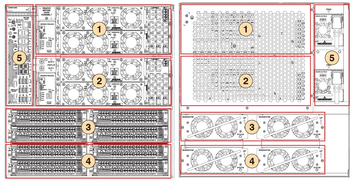
The following table describes the airflow in a fully loaded NCS 1020 chassis.

Table 2. Airflow in a Fully Loaded NCS 1020 Chassis

Callout

Airflow Channel

Airflow Process

1

Channel 1

Pair of front fan trays at top cool the Type 1 line card and controller in slot 0.

2

Channel 2

Pair of front fan trays at bottom cool the Type 1 line card and controller in slot 1.

3

Channel 3

Rear fan trays in slots FT4 and FT5 cool the Type 2 line cards in slots 2, 3, 4, and 5.

4

Channel 4

Rear fan trays in slots FT6 and FT7 cool the Type 2 line cards in slots 6, 7, 8, and 9.

5

Channel 5

Built-in fans in the PSUs cool the EITU and SSD on the front.

External Interface Timing Unit

The External Interface Timing Unit (EITU) manages the control plane interfaces and includes all user external interfaces (timing and management). It is connected to the controller with a redundant 10 G Ethernet bus.

EITU is a fixed part of the chassis and it is not removable or replaceable in the field.

Figure 4. Front View of EITU

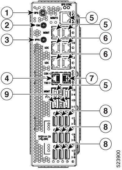
The following is the list of the available interfaces:

1

Coaxial connector for GPS antenna RF input (with 5 V antenna power, if necessary) (1x)

2

Coaxial connector for 10 MHz sync signal (bidirectional) (1x)

3

Coaxial connector for 1PPS sync signal (bidirectional) (1x)

4

Console/Universal Asynchronous Receiver/Transmitter (UART) Interface (1x)

5

10/100/1000 RJ-45 Ethernet management ports and Interconnection Link (ILINK) (5x)

Note


In R24.2.11, the MGMT 3 and 4 ports are SFP that support 1 GE optical PTP (1588 and SyncE) (2x)

6

SFP for 1 GE optical User Data Channels (UDC) (4x)

7

RJ-45 for 1588 TOD (1x)

8

USB 2.0 type A, 1.8 A max at 5 V / 12 V (9x)

Note

 
The USB ports in the EITU do not support USB drives; they only support passive optical devices from Cisco, such as breakout modules and mux/demux patch panels. If you want to install the operating system or copy files to and from the system, use the USB 3.0 ports labeled "Boot" on the controller cards.

9

SFP for 1 GE optical PTP port (1588 and SyncE) (2x)

PIDs

The following tables list the PIDs of the Cisco NCS 1020 and its modules:

Table 3. Shelf and Accessory Option

Product ID

Product Description

NCS1020-SA=

NCS 1020 Shelf Assembly

NCS1020-SYS=

NCS 1020 Assemble to Order

NCS1020-SYS-FULL=

NCS 1020 Assemble to Order, Full

NCS1020-19-KIT=

NCS 1020 Accessory Kit for 19-inch racks

NCS1020-23-KIT=

NCS 1020 Accessory Kit add-on for 23inch racks

NCS1020-ETSI-KIT=

NCS 1020 Accessory Kit add-on for ETSI racks

Table 4. SSD Option

Product ID

Product Description

NCS1010-SSD=

NCS 1010 SSD for NCS 1012,1020

Table 5. Controller Option

Product ID

Product Description

NCS1010-CTR2-K9=

NCS 1010, 1012, 1020 Controller, 112500 bps Default Console Baud Rate

NCS1010-CTR2-B-K9=

NCS 1010, 1012, 1020 Controller, 9600 bps Console Baud Rate

Table 6. Fan Option

Product ID

Product Description

NCS1010-FAN=

NCS 1010 Shelf Fan Assembly

NCS1020-FAN=

NCS 1020 Fan for NCS 1014 Slots

NCS1020-FAN-BLANK=

NCS 1020 Fan Blank

Table 7. Power Supply Option

Product ID

Product Description

NCS1K4-DC-PSU-2=

NCS 1004 DC Power Supply Unit, 2.5 kW

NCS1K4-AC-PSU-2=

NCS 1004 AC Power Supply Unit, 2.5 kW

Table 8. Line Card Option–Type 1 Cards

Product ID

Product Description

NCS1K-OLT-C=

C-band Optical Line Terminal without Raman

NCS1K-E-OLT-C=

C-band Optical Line Terminal without Raman, enhanced

Table 9. Line Card Option–Type 2 Cards

Product ID

Product Description

NCS1K14-CCMD-16-C=

NCS 1000 16 port Colorless Direct attach LC with EDFA, C-band

Table 10. Line Card Filler/Blank Option

Product ID

Product Description

NCS1010-FLR-P=

Filler / Blank for NCS 1010 Slot on NCS 1012, 1020, Passive

NCS1010-FLR-A=

Filler / Blank for NCS 1010 Slot on NCS 1012, 1020, Active, with Fan slots

NCS1010-CTR2-FLR=

Filler / Blank for Controller Slot on NCS 1012, 1020

NCS1K14-BLANK=

Network Convergence System 1014 Blank card

Table 11. Door Option

Product ID

Product Description

NCS1020-DR=

NCS 1020 Door with Filters

NCS1020-DR-FTF=

Replaceable Air Filter

Safety Precaution for Laser Radiation

Cisco NCS 1020 is classified as Hazard Level 1M as per IEC 60825-2 and Laser Class 1/1M as per IEC 60825-1, since it may include Class 1 or Class 1M Laser sources.

Invisible laser radiation is present. Do not expose to users of telescopic optics. This applies to Class 1/1M laser products.

Figure 5. Class 1M Laser Product Label
Class 1M Laser Product Label
Figure 6. Class 1M Laser Product Label

Statement 1055


Warning


Invisible laser radiation may be emitted from disconnected fibers or connectors. Do not stare into beams or view directly with optical instruments. Statement 1051


Line Cards

The Cisco NCS 1020 chassis supports the following line cards:


Note


The NCS 1020 chassis supports the Type 1 (NCS 1010) line cards in card slots 0 and 1. It supports the Type 2 (NCS 1014) line cards in card slots 2–9.

Note


When not used, fill the empty Type 1 line card slots with either Active Filler (NCS1010-FLR-A) or Passive Filler (NCS1010-FLR-P). Similarly, fill the empty Type 2 line card slots with NCS 1014 filler cards (NCS1K14-BLANK). For more information on the filler modules, see Cisco NCS 1020 Filler Modules.


Note


In the following sections, the OLT line cards are Type 1 line cards and CCMD-16-C line card is Type 2 line card.


NCS1K-OLT-C Line Card

The C-band Optical Line Terminal without Raman (OLT-C) line card includes the following features:


Note


The NCS1K-OLT-C line card refers to OLT-C line card in this section.


  • 25-dBm line preamplifier True Variable Gain (TVG) Erbium-Doped Fiber Amplifier (EDFA) with two switchable gain ranges

  • Dedicated amplification of the odd and even add channels through an embedded Fixed Gain (FG) EDFA

  • 23-dBm line boost-amplifier TVG EDFA single gain range

  • Dedicated EDFA for noise loading

  • Embedded Optical Time Domain Reflectometer (OTDR) for line RX and TX monitoring

  • 37 ports Optical Channel Monitoring (OCM)

  • Dedicated Tunable Laser (TL) enabling Connection Verification (CV) and patch cord discovery features

  • Up to 30 EXP ports

  • Embedded Optical Service Channel at Fast Ethernet (FE)

  • Multiplexing and demultiplexing of odd and even channels

  • C+L combiner for multiplexing and demultiplexing L-band channels

  • 2x2 switch to reverse transmit direction of Optical Service Channel (OSC)-C

  • Fiber reflectors to support fiber end detection by OTDR

Figure 7. Front View of OLT-C Line Card
Figure 8. Perspective View of OLT-C Line Card

E-OLT-C Line Card

The C-band Optical Line Terminal without Raman, Enhanced (E-OLT-C) line card includes the following features:

  • 25-dBm line preamplifier True Variable Gain (TVG) Erbium-Doped Fiber Amplifier (EDFA) with two switchable gain ranges

  • Dedicated amplification of the odd and even add channels through an embedded Fixed Gain (FG) EDFA

  • 23-dBm line boost-amplifier TVG EDFA single gain range

  • Dedicated EDFA for noise loading

  • Embedded Optical Time Domain Reflectometer (OTDR) for line RX and TX monitoring

  • 37 ports Optical Channel Monitoring (OCM)

  • Dedicated Tunable Laser (TL) enabling Connection Verification (CV) and patch cord discovery features

  • Up to 30 EXP ports

  • Embedded Optical Service Channel at Fast Ethernet (FE)

  • Multiplexing and demultiplexing of odd and even channels

  • C+L combiner for multiplexing and demultiplexing L-band channels

  • 2x2 switch to reverse transmit direction of Optical Service Channel (OSC)-C

  • Fiber reflectors to support fiber end detection by OTDR

Figure 9. Front View of E-OLT-C Line Card
Front View of E-OLT-C Line Card
Figure 10. Perspective View of E-OLT-C Line Card
Perspective View of E-OLT-C Line Card

CCMD-16-C Line Card

The NCS 1000 16-port Colorless Mux/Demux Optical (CCMD-16-C) Line Card is a multiplexing and demultiplexing unit with fixed gain EDFAs on both Add and Drop sections. The optical line card provides colorless functionality on the add/drop ports. It multiplexes any wavelength with the flexible options of baud rate and modulation format to the line side ROADM or amplifier units for transmission. It transmits and receives signals from optical line terminal (OLT) units.

In the Cisco NCS 1020 chassis, you can install the optical line card in one or more card slots.


Note


The chassis supports the NCS 1014 CCMD-16 line cards in card slots 2–9.

The optical line card has:

  • Two line ports to transmit and receive using the same LC connectors.

  • 16 ports for add/drop with LC connector-based interfaces

There are two variants of the optical line card:

  • NCS1K14-CCMD-16-C

    The NCS1K14-CCMD-16-C line card is a C-band, 16-port Colorless Direct attach optical line card with EDFA. It can host up to 16 channels. It supports any signal distribution between 191250 and 196200 GHz, for example, the 64 channels grid with 75-GHz spacing.

    The following table summarizes the central frequency of the first and the last channel of this specific grid.

    Table 12. C-Band Channel Wavelength Plan

    Channel

    Central Frequency (THz)

    Wavelength (nm)

    1

    196.100

    1528.77

    64

    191.375

    1566.52

  • NCS1K14-CCMD-16-L

    The NCS1K14-CCMD-16-L line card is an L-band, 16-port Colorless Direct attach optical line card with EDFA. It can host up to 16 channels. It supports any signal distribution between 186025 and 191000 GHz, for example, the 64 channels grid with 75-GHz spacing.

    The following table summarizes the central frequency of the first and the last channel of this specific grid.

    Table 13. L-Band Channel Wavelength Plan

    Channel

    Central Frequency (THz)

    Wavelength (nm)

    1

    190.850

    1570.83

    64

    186.125

    1610.7

Figure 11. NCS1K14-CCMD-16 Line Card Front View
f

The following table shows the port names and their connector types for both CCDM-16-C and CCMD-16-L cards.

Table 14. Line Card Interface and Connector Assignment

Callout

Connector Label

Connector Type

Port Name

1

MON

LC

MON TX

MON RX

2

COM

LC

COM TX

COM RX

3

A/D 1…16

LC

A/D TX [1…16]

A/D RX [1…16]

L-Band Cover

The Type 1 line card comes preinstalled with an L-band cover for safety. The L-band cover has the DO NOT USE label on its face and covers the L-band port.

Figure 12. L-Band Cover

Caution


Remove the cover without disturbing the fiber optic cables in the adjacent ports.


Figure 13. Type 1 Line Card with L-Band Cover

The following table provides the details on when to remove the L-band cover in the field based on your network configuration.

Configuration

Action

C-Band Only

Need not remove the covers in the field.

C+L Band

Remove the covers before connecting the fiber optic cables.

Future L-Band Upgrade

Remove the covers during the maintenance window only without disturbing the fiber optic cables in the adjacent ports.

For more information on the removal of the L-band cover, see Remove the L-Band Cover.

Cisco NCS 1020 Modules

The Cisco NCS 1020 chassis supports the following modules:

SSD

The field-replaceable SSD is accessible from the front of the Cisco NCS 1020 chassis. This chassis SSD acts as the backup software storage in case the SSD inside the CPU fails. It has 480 GB storage space to store the running software and configuration. This backup storage enables Cisco NCS 1020 to quickly recover to functional state if either route processor (RP) corruption or replacement occurs.

Figure 14. Perspective View of the SSD

Controller Cards

The Cisco NCS 1020 chassis has slots to accommodate up to two controllers. It supports single controller and dual controller configurations.

The chassis supports controller card redundancy through Active and Backup controller cards. The backup controller card, also called as peer controller card, stays in standby state and remains non-functional. When the system detects a fault in the active controller card, the system moves the active controller card to the fault state. Then, the backup controller card transitions to the active state and starts to function. The switchover process is entirely hardware based and increases the chassis availability.


Note


When you do not need the backup controller card, you must cover the empty slot for the controller card with a controller filler.

The Cisco NCS 1020 chassis supports the following controller cards:

NCS1010-CTR2-K9

The NCS1010-CTR2-K9 controller card supports a default of 115200 bps baud rate on the RS232 console port. The controller card has a USB 3.0 port and six status LEDs. For details of the NCS1010-CTR2-K9 controller card, see Front View of the NCS1010-CTR2-K9 Controller.


Note


In R24.2.11, the NCS1010-CTR2-K9 controller card supports only USB 2.0 drive in the USB port.


Figure 15. NCS1010-CTR2-K9 Controller Card

NCS1010-CTR2-B-K9

The NCS1010-CTR2-B-K9 controller card supports a default of 9600 bps baud rate on the RS232 console port. The controller card has a USB 3.0 and six status LEDs. For details of the NCS1010-CTR2-B-K9 controller card, see Front View of the NCS1010-CTR2-B-K9 Controller.


Note


In R24.2.11, the NCS1010-CTR2-B-K9 controller card supports only USB 2.0 drive in the USB port.


Figure 16. NCS1010-CTR2-B-K9 Controller Card

Fan Trays

NCS1020 has two fan sections:

Front Fan Section

The front fan section consists of four fan tray slots (FT0, FT1, FT2, FT3). Each fan tray consists of three fan units (Fan 0, Fan 1, Fan 2) and a Status LED.

Figure 17. Front Fan Tray (NCS1010-FAN=)

1

Front fan tray LED

Rear Fan Section

The rear fan section consists of four fan tray slots (FT4, FT5, FT6, FT7). Each fan tray consists of two fan units (Fan 0, Fan 1) and a Status LED.

Figure 18. Rear Fan Tray (NCS1020-FAN=)

1

Rear fan tray LED

Power Supply

The Cisco NCS 1020 chassis has two slots for 2.5-kW AC and DC redundant PSUs. Both the PSUs must always remain installed in the chassis, except during replacement. When the chassis has only one PSU installed, the system raises the Power Module Redundancy Lost alarm.

2.5-KW PSUs (NCS1K4-AC-PSU-2 and NCS1K4-DC-PSU-2)

2.5-kW PSU power derating and option table, including ambient temperature details are here. The power details are for output power.

  • AC high voltage range output power—2500 W up to 40-degree C for 1 PSU; 2500 W up to 55-degree C for 2 PSUs (for a short duration, as specified by Telcordia GR-63-Core).

  • AC low voltage range output power—1500 W up to 40-degree C for 1 PSU; 1500 W up to 55-degree C for 2 PSUs (for a short duration, as specified by Telcordia GR-63-Core).

  • DC power supply—2500 W output power up to 40-degree C for 1 PSU; 2500 W up to 55-degree C for 2 PSUs (for a short duration, as specified by Telcordia GR-63-Core).

For power specifications, see Power Specifications.

Power Supply Units (PSUs)

The redundant, field-replaceable PSUs power the Cisco NCS 1020 chassis. The chassis has slots for two PSUs at the rear side. Each PSU supports up to 2.5 kW per system.

The PSUs have internal fans to regulate the temperature inside the PSUs. The fans in the PSU receive power from the main PSU or the standby PSU. The PSUs are available in reverse airflow (RAF) direction meaning the airflow direction is from the output connector to the input connector.

To ensure the necessary fan redundancy, the two PSUs implement a protection mechanism. When the mechanism detects a single PSU failure or if a PSU fails to power up, it triggers all the operational fans to run at maximum speed. This mechanism activates without intervention from the software.

The Cisco NCS 1020 chassis supports the following PSUs:

NCS1K4-AC-PSU-2

NCS1K4-AC-PSU-2 is a 2.5-kW AC to DC, power-factor-corrected (PFC) power supply that converts standard AC power into a main output of 12 VDC.

Figure 19. NCS1K4-AC-PSU-2
This image displays a NCS1K4-AC-PSU-2 AC power supply unit.
NCS1K4-DC-PSU-2

NCS1K4-DC-PSU-2 is a 2.5-kW DC to DC, PFC power supply with 12 VDC (main) and 12 VDC (standby) output.

Figure 20. NCS1K4-DC-PSU-2
This image displays a NCS1K4-DC-PSU-2 DC power supply unit.

Cisco NCS 1020 Filler Modules

The Cisco NCS 1020 chassis accommodates different filler modules based on the chassis configurations. Each filler module has a predetermined slot to occupy.


Important


Install the filler modules in the empty slots of the chassis to prevent overheating and dust formation.


The Cisco NCS 1020 chassis supports the following filler modules.

Controller Filler

Controller filler (NCS1010-CTR2-FLR) is the filler module for the controller slots.

When to Use the Controller Filler

Add the controller filler, when you do not need the backup controller.

Type 1 Line Card Filler

  • Active Filler for Type 1 Line Cards

    Active Filler (NCS1010-FLR-A) is the filler module for type 1 line cards. It has slots for the front fan trays to ensure proper airflow to the controller. This filler is similar to the Type 1 line cards but it doesn’t contain the OLT or ILA modules.


    Remember


    Active filler is supported in slot 1.


    When to Use the Active Filler for Type 1 Line Cards

    If your chassis needs a backup controller without the need for the corresponding type 1 line card, install the active filler into the empty slot. The active filler occupies the empty slot, providing the additional benefit of cooling the backup controller.

    This setup is useful for disaster recovery and C-band only configuration.

  • Passive Filler for Type 1 Line cards

    Passive Filler (NCS1010-FLR-P) acts as the filler module for type 1 line cards. It’s different from the Active Filler and doesn’t have slots for fan trays. Similar in size to the Type 1 line cards, this filler doesn’t contain the OLT or ILA modules.


    Remember


    Passive filler is supported in slot 1.


    When to Use the Passive Filler for Type 1 Line Cards

    If your chassis doesn’t need a backup controller, install the passive filler into the empty type 1 card slot.

    This setup is useful for operating a C-band only network without disaster recovery.

Type 2 Line Filler

Type 2 filler cards (NCS1K14-BLANK) are designed to fill the empty slots in the type 2 card section.


Remember


Type 2 filler cards are supported in card slots from 2 to 9.


When to Use the Type 2 Filler Card

If you don't intend to use the type 2 line card in your configuration, install the type 2 filler card into the empty slots.

Filler Fan Tray

Filler fan tray (NCS1020-FAN-BLANK) is the filler module for the rear fan trays.


Remember


Filler fan trays are supported in fan slots from FT4 to FT7 at the rear.


When to Use the Filler Fan Tray

When type 2 filler cards are present in slots 2, 3, 4, and 5, install the filler fan trays in the slots FT4 and FT5 at the rear.

When type 2 filler cards are present in slots 6, 7, 8, and 9, install the filler fan trays in the slots FT6 and FT7 at the rear.

Slot Assignment for Filler Modules

The following table shows the supported filler modules and their associated slots in the chassis.

Table 15. Applicable Slots for Filler Modules

PID

Filler Module

Applicable Slots

NCS1010-FLR-A

Active Filler for Type 1 line cards

1

NCS1010-FLR-P

Passive Filler for Type 1 line cards

1

NCS1010-CTR2-FLR

Controller filler

SLOT-1

NCS1020-FAN-BLANK

Filler fan tray

FT4–FT7

NCS1K14-BLANK

Type 2 filler card

2–9

NCS 1020 Chassis Configurations with Filler Modules

NCS 1020 Chassis with Passive Filler, Controller Filler, Type 2 Filler Card

The following image shows the NCS 1020 chassis with passive filler, controller filler, and type 2 filler cards.

Figure 21. C-Band Only NCS 1020 Chassis with Passive Filler, Controller Filler, Type 2 Filler Card

1

SSD

4

Type 2 line cards

7

Front fan trays

2

EITU

5

Type 2 filler cards

8

Type 1 line card

3

Controller filler

6

Controller card

9

Passive filler for Type 1 line card

NCS 1020 Chassis Rear View with Filler Fan Tray

The following image shows the NCS 1020 chassis with filler fan tray.

Figure 22. NCS 1020 Chassis Rear View with Filler Fan Tray

10

PSU

12

Filler fan trays

11

Rear fan trays

NCS 1020 Chassis Front View with Active Filler

The following image shows the NCS 1020 chassis with active filler.

Figure 23. C-Band Only NCS 1020 Chassis with Active Filler

1

SSD

4

Front fan trays

2

EITU

5

Type 1 line card

3

Controller cards

6

Active filler for type 1 line card

7

Type 2 line cards

Cisco NCS 1020 Front Door Kit (NCS1020-DR=)

The NCS 1020 Doors with air filters (NCS1020-DR=) kit keeps the NCS 1020 chassis clean in a dusty environment and safe inside cabinets without doors. The door kit features a replaceable, internal air filter that prevents dust or foreign particles from entering the chassis. It also has grounding straps for safety, hex openings for efficient airflow and pull hinges for quick attachment onto the chassis.

The front door LEDs (SYS and ATT) mimic the behaviour of the SYS and ATT LEDs on the controller, only when the door is closed. The fiber management brackets on the sides position and route the fiber-optic cables to prevent cluttering of cables.

Figure 24. Fiber Management Brackets

1

Left side bracket

2

Top hood and bottom cover screws

3

Right side bracket

4

Top hood

5

Bottom cover

The dimensions of the Cisco NCS 1020 chassis with and without door varies.

Figure 25. Cisco NCS 1020 Chassis Dimensions—With and Without Front Door