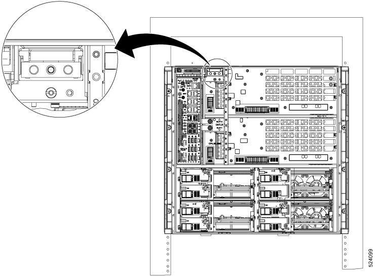
Install the Controller/Controller Filler
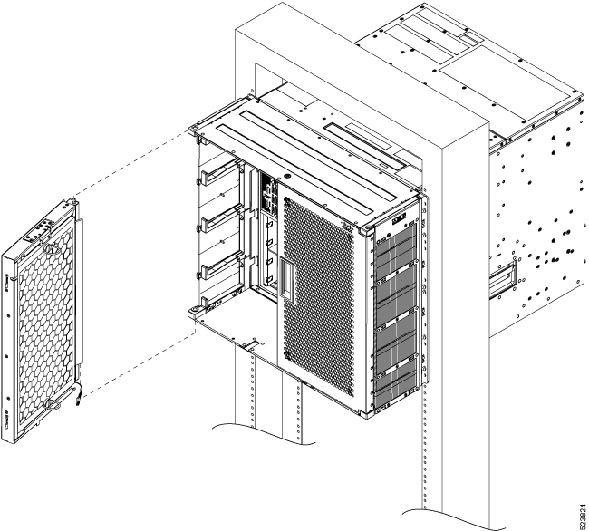
Use this procedure to install the controller into the Cisco NCS 1020 chassis. The chassis can accommodate up to two controllers.
 Note |
This procedure also applies to controller filler installation. |
Attention |
The following table shows controller assignment for the Type 1 line and filler cards. |
|
CNTLR Slot |
Module |
Supported Card |
|---|---|---|
|
0 |
Controller |
Top Type 1 line card |
|
1 |
Controller |
Bottom Type 2 line card |
|
Controller filler |
Bottom Type 2 filler card |
Procedure
|
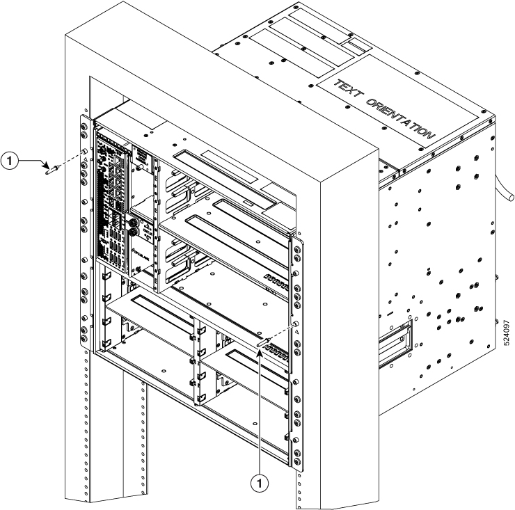
Step 1 |
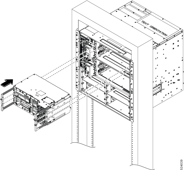
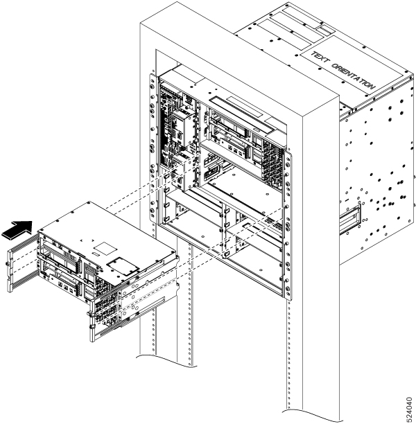
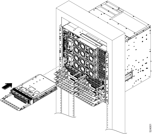
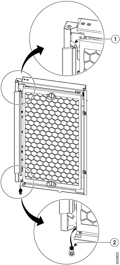
Orient the controller appropriately before inserting. Check for the This Side Up label. |
|
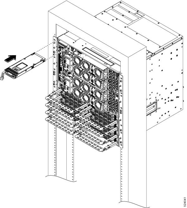
Step 2 |
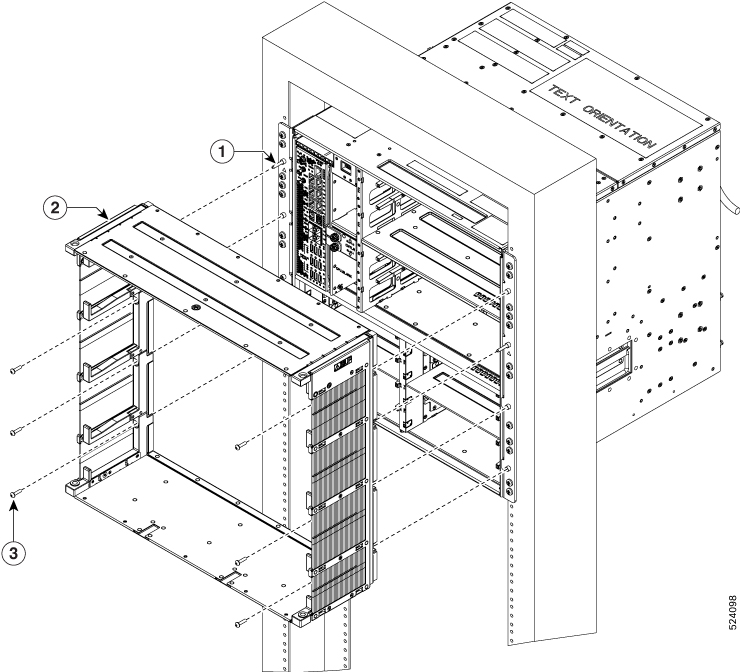
Support the bottom of the controller with hands and insert the controller into the slot. 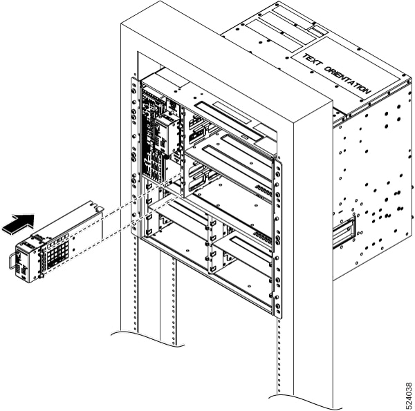
|
|
Step 3 |
Using a screwdriver, tighten the two captive screws to a torque value of 0.65 N-m (5.75 lbs-in). |


 Feedback