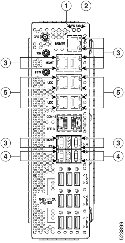
LEDs

This section provides details of the LEDs in the Cisco NCS 1020 modules, controller unit, and line cards.

EITU LEDs

The EITU has 24 LEDs indicating the status of its ports.

Figure 1. EITU LEDs
d

1

GPS LED

4

PTP (Ethernet Optical SFP Ports) LEDs

2

SYNC LED

5

UDC (Ethernet Optical SFP Ports) LEDs

3

MGMT (Ethernet Copper Ports) LEDs

The following table shows the LEDs of EITU and their status.

Table 1. Status of the EITU LEDs

LED

Color

Status

GPS LED

Green

GPS phase is locked.

Yellow

GPS is enabled.

Off

GPS is not enabled.

Red

GPS is used.

Sync LED

Green

Time core is synchronized to an external source including IEEE1588.

Flashing green

System is in Synchronous Ethernet mode.

Amber

Acquiring state or Holdover: Time core is in acquiring state or holdover mode.

Off

Time core clock synchronization is disabled or in a free-running state.

Ethernet Copper Ports (MGMT 0/1/2/3/4) LEDs

Green

The link is ON.

Yellow

Link is up but without traffic.

Flashing yellow

Link is up but with traffic.

Ethernet Optical SFP Ports (PTP0/1, UDC 0/1/2/3) LEDs

Green

Duplex or traffic collision are present.

Yellow

Link is up but without traffic.

Flashing yellow

Link is up but with traffic.

Controller LEDs

The controller (NCS1010-CTR2-K9 and NCS1010-CTR2-B-K9) units have one USB port and six LEDs to indicate the system status and the status of the components.

Figure 2. Front View of the NCS1010-CTR2-K9 Controller
Figure 3. Front View of the NCS1010-CTR2-B-K9 Controller

1

Bluetooth Low Energy (BLE) Status LED

5

Power Supply Status LED

2

USB Interface

6

Attention LED

3

System Status LED

7

ACT LED

4

Fan Status LED

Table 2. Status of the Controller LEDs

LED

Controller/System Status

Default Status of LED

Color

Status

BLE LED

System is up and running

Off

Green

Idle in Data mode.

Orange

Idle in Command mode.

Purple

Waiting for a pairing device.

Blue

Active and data is transferring.

Blue (flashing)

Active and connected.

System LED

During controller boot up

Red

Red

Controller is powering ON.

Red (flashing slowly)

BIOS loading.

Yellow (flashing slowly)

Operating system loading.

Red (flashing fast)

Secure boot failure. Replace the controller.

Yellow (flashing fast)

Controller is not seated properly. Remove and replace the controller properly.

System LED

Controller is operational

Red

Red

Major or critical alarm is active.

Yellow

Minor alarm is active.

Green

The module is operational and has no active alarms.

Fan LED

System is up and running

Red

Green

No alarm is present for the fans.

Red

Either a fan is missing from its slot or is faulty.

PSU LED

System is up and running

Red

Green

All PSUs present in the chassis are in working condition.

Red

Either a PSU is missing from its slot or is faulty, or there is no input power.

Attention LED

System is up and running

Off

Blue

Used to identify a specific chassis in a rack or room. Use this LED for troubleshooting purposes such as replacing the fiber and field-replaceable units. You can control it through the software CLI.

Use the following command to activate this LED, manually:

hw-module attention-led location 0/RP0/CPU0

ACT LED (active controller)

After controller plug-in

Green

Red

Redundant controller unit (RCU) is enabled but the controller is missing from its slot or is faulty.

Green

RCU is enabled and the controller functions as an active controller.

Off

RCU is disabled.

ACT LED (backup controller)

After controller plug-in

Off

Red

RCU is enabled but the controller is missing from its slot or is faulty.

Yellow

RCU is enabled and the controller functions as a backup controller.

Off

RCU is disabled.

CCMD-16-C and CCMD-16-L Line Card LED


Note


In Release 24.2.11, the Cisco NCS 1020 chassis supports the Type 2 CCMD-16-C line card LEDs only.


The CCMD-16-C and CCMD-16-L optical line cards have 18 LEDs each to indicate the system status and the status of the optical ports.

The following information applies to both CCMD-16-C and CCMD-16-L cards.

Figure 4. CCMD-16-C Optical Cards LEDs

Callout

LED

1

COM

2

A/D-1…A/D-16

3

ACT

Table 3. Status of the CCMD-16-C and CCMD-16-L Optical Card LEDs

LED

Color

Status

ACT

Amber (solid)

The line card is booting. This color appears when you insert the line card into the chassis.

Flashing Red

The line card is faulty.

Green

The line card is up and operational—not associated to the traffic status.

COM, A/D-1…A/D-16

Off

The port is not provisioned.

Red

Major alarm that could lead to a traffic impacting situation.

Green

The module is operational and has no alarm.

Amber (solid)

Minor alarm (such as low Rx or Tx power) that could lead to a traffic impacting situation.

Amber (flashing)

This is used for troubleshooting, to identify the faulty port of an LC.

Use the controller optics command in the configuration mode to point to a faulty port in the LC.

The port is configured in maintenance mode or the attention LED is enabled for this port.

Note


Attention LED is not supported on ACT LED.

Front Fan Tray LED

The fan tray has one LED to indicate its status.

Figure 5. Front View of the Fan Tray

1

Fan tray LED

The following table has details of the fan tray LED:

Table 4. Status of the Fan Tray LED

LED

Color

Status

Fan LED

Amber

Indicates that the fan speed is out of expected range such as fan is not rotating. Also, indicates that the fan speed is not readable.

Red

Indicates a fault in the fan tray.

Green

Indicates that the fan tray is working fine.

Rear Fan Tray LED

The fan tray has one LED to indicate its status.

Figure 6. Rear Fan Tray Front View

1

Fan tray LED

The following table has details of the fan tray LED:

Table 5. Status of the Fan Tray LED

LED

Color

Status

Fan LED

Amber

Indicates that the fan speed is out of expected range such as fan is not rotating. Also, indicates that the fan speed is not readable.

Red

Indicates a fault in the fan tray.

Green

Indicates that the fan tray is working fine.

Power Supply Unit (PSU) LED

The NCS1K4-AC-PSU-2 and NCS1K4-DC-PSU-2 units have one LED each to indicate their status.

Figure 7. Front View of 2.5-kW AC PSU
Figure 8. Front View of 2.5-kW DC PSU

1

PSU Unit (STATUS) LED

Table 6. Status of the 2.5-kW PSU LED

Color

Status

Amber

There exists no input to the PSU, provided the other PSU is working.

Off

Both PSUs do not have input.

Green

The input to the PSU is valid.

NCS 1020 Front Door LEDs

The Cisco NCS 1020 Front Door (NCS1020-DR=) has two LEDs to indicate the system status and identify the chassis in the rack. the door LEDs mimic the ATT and SYS LEDs of the controller. This setup is done to avoid opening the door often to check the status of the chassis.


Note


The door LEDs come up only when you have properly mated the chassi connector with door connector.


For LED indications, see the SYS and ATT LEDs of the controller.