NCS 1010 Chassis and Line Cards
Cisco NCS 1010 is a next-generation optical line system optimized for ZR/ZR+ WDM router interfaces. Its salient features are:
-
Provides point-to-point connectivity between routers with WDM interfaces.
-
Multiplexes the signals received from multiple routers over a single fiber.
-
With one MPO port, it can be scaled to 8 Degree.
-
Caters to C-band WDM transmission to maximize capacity, and can be enhanced to C+L combined band in the future.
Cisco NCS 1010 is a 3RU chassis that has an in-built External Interface Timing Unit (EITU) and the following field-replaceable modules.
-
Controller
-
Two power supply units
-
Two fan trays
-
Fan filter
-
Line card
See Hardware Installation Guide for Cisco NCS 1010 and Cisco NCS 1000 Passive Modules for more detailed images.
Line Cards
There are five different variants of the line card:
-
OLT-C Line Card: C-band Optical Line Terminal without Raman
-
OLT-R-C Line Card: C-band Optical Line Terminal with Raman
-
ILA-C Line Card: C-band In-Line Amplifier without Raman
-
ILA-R-C Line Card: C-band In-Line Amplifier with one side Raman
-
ILA-2R-C Line Card: C-band In-Line Amplifier with both sides Raman
-
OLT-L Line Card: L-band Optical Line Terminal
-
ILA-L Line Card: L-band In-Line Amplifier
OLT-C Line Card
The C-band Optical Line Terminal without Raman (OLT-C) line card includes the following features:
-
25-dBm line preamplifier True Variable Gain (TVG) Erbium-Doped Fiber Amplifier (EDFA) with two switchable gain ranges
-
Dedicated amplification of the odd and even add channels through an embedded Fixed Gain (FG) EDFA
-
23-dBm line boost-amplifier TVG EDFA single gain range
-
Dedicated EDFA for noise loading
-
Embedded Optical Time Domain Reflectometer (OTDR) for line RX and TX monitoring
-
37 ports Optical Channel Monitoring (OCM)
-
Dedicated Tunable Laser (TL) enabling Connection Verification (CV) and patch cord discovery features
-
Up to 30 EXP ports
-
Embedded Optical Service Channel at Fast Ethernet (FE)
-
Multiplexing and demultiplexing of odd and even channels
-
C+L combiner for multiplexing and demultiplexing L-band channels
-
2x2 switch to reverse transmit direction of Optical Service Channel (OSC)-C
-
Fiber reflectors to support fiber end detection by OTDR
OLT-R-C Line Card
The C-band Optical Line Terminal with Raman (OLT-R-C) line card includes the features of the OLT-C line card along with the Raman amplifier.
The following are the features of the Raman amplifier:
-
Five different pump wavelengths for supporting C+L Raman amplification
-
Embedded Distributed Feedback (DFB) laser at 1568.77 nm (class 1M) to be used for optical safety (link continuity)
-
Full monitoring of pumps, DFB laser and signal power
-
Raman pump back-reflection detector
-
Meets class 1M Laser safety.
-
Additional Photodiode (PD) to monitor remnant pump power at the far end
ILA-C Line Card
The C-band In Line Amplifier without Raman (ILA-C) line card includes the following features:
-
Two independent TVG EDFA block, covering full operative gain ranging 8–36 dB
-
Each EDFA block can provide up to 23 dBm output power
-
Dynamic Gain Equalization (DGE) embedded capability to compensate for line tilt and ripple
-
Embedded OTDR for line1/2-RX/TX monitoring
-
Four-ports OCM for channels monitoring
-
Embedded Optical Service Channel at Fast Ethernet (FE)
-
C+L combiner for multiplexing/demultiplexing L-band channels
-
Dedicated ports for amplifiers output monitoring
-
2x2 switch to reverse transmit direction of OSC-C for both directions
-
Fiber reflectors to support fiber end detection by OTDR
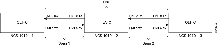
The following image displays the port connection between the ILA-C line card and OLT-C line cards.
ILA-R-C Line Card
The C-band In Line Amplifier with Raman (ILA-R-C) line card includes the features of ILA-C and Raman amplifier.
ILA-2R-C Line Card
The C-band In-Line Amplifier with two Raman (ILA-2R-C) line card includes the features of the ILA-C and Raman amplifier on both directions.
OLT-L Line Card
The L-band Optical Line Terminal (OLT-L) line card includes the following features:
-
25-dBm line preamplifier True Variable Gain (TVG) Erbium-Doped Fiber Amplifier (EDFA) with two switchable gain ranges
-
Dedicated amplification of the odd and even add channels through an embedded Fixed Gain (FG) EDFA
-
24.5-dBm line boost-amplifier TVG EDFA single gain range
-
15-dBm ADD-side boost-amplifier TVG EDFA with single gain range of 16 dB
-
Dedicated EDFA for noise loading
-
37 ports Optical Channel Monitoring (OCM)
-
Dedicated Tunable Laser (TL) enabling Connection Verification (CV) and patch cord discovery features
-
Up to 30 EXP ports
-
Embedded Optical Service Channel at Fast Ethernet (FE) at 184.45 THz (1625.33 nm)
-
Multiplexing and demultiplexing of odd and even channels
-
2x2 switch to reverse transmit direction of Optical Service Channel OSC-L
ILA-L Line Card
The L-band In Line Amplifier (ILA-L) line card includes the following features:
-
Two independent TVG EDFA block, covering full operative gain ranging 10.8–32.8 dB
-
Each EDFA block can provide up to 24.5-dBm total output power
-
Dynamic Gain Equalization (DGE) embedded capability to compensate for line tilt and ripple
-
Four-ports OCM for channels monitoring
-
Embedded Optical Service Channel at Fast Ethernet (FE)
-
Dedicated ports for amplifiers output monitoring
-
2x2 switch to reverse transmit direction of OSC-L for both directions
External Interface Timing Unit
The External Interface Timing Unit (EITU) manages the control plane interfaces and includes all user external interfaces (timing and management). It is connected to the controller with a redundant 10G Ethernet bus.
The following is the list of the available user interfaces:
-
Coaxial connector for GPS antenna RF input (with +5V antenna power, if necessary)
-
Console/Universal Asynchronous Receiver/Transmitter (UART) Interface (1x)
-
Two Small Form-Factor Pluggables (SFP) for 1GE optical PTP port (1588 and SyncE)
-
Two SFPs for 1GE optical User Data Channels (UDC)
-
Three USB 2.0 type A, 1.8A max @5V/12V (with Cisco NCS 1000 Breakout Patch Panel support)
-
Coaxial connector for 10MHz sync signal (bidirectional)
-
Coaxial connector for 1PPS sync signal (bidirectional)
-
RJ45 for 1588 TOD (1x)
-
Three 10/100/1000 RJ-45 Ethernet management ports and Interconnection Link (ILINK)
 Feedback