Boot NCS 1010
Use the console port to connect to NCS 1010. By default, the console port connects to the XR mode. If necessary, you can establish subsequent connections through the management port, after it is configured.
Procedure
|
Step 1 |
Connect a terminal to the console port of the RP. |
||
|
Step 2 |
Start the terminal emulation program on your workstation. The console settings are 115,200 bps, 8 data bits, 1 stop bit and no parity. |
||
|
Step 3 |
Power on NCS 1010. To power on the shelves, install the AC or DC power supplies and cables. As NCS 1010 boots up, you can view the boot process details at the console of the terminal emulation program. |
||
|
Step 4 |
Press Enter. The boot process is complete when the system prompts you to enter the root-system username. If the prompt does not appear, wait for a while to give NCS 1010 more time to complete the initial boot procedure; then press Enter.
|
Boot NCS 1010 Using USB Drive
The bootable USB drive is used to reimage NCS 1010 for system upgrade or to boot the NCS 1010 in case of boot failure. A bootable USB drive is created by copying a compressed boot file into a USB drive. The USB drive becomes bootable after the contents of the compressed file are extracted.
You can complete this task using the Windows, Linux, or MAC operating systems available on your local machine. The exact operation to be performed for each generic step that is outlined here depends on the operating system in use.
Use this task to boot the NCS 1010 using the USB drive.
Before you begin
-
You need a USB drive with a storage capacity of at least 4 GB.
-
The USB drive should have a single partition.
-
NCS 1010 software image can be downloaded from Software Download page on Cisco.com.
-
Copy the compressed boot file from the software download page at Cisco.com to your local machine. The filename for the compressed boot file is in the format ncs1010-usb-boot-<release_number>.zip.
Procedure
|
Step 1 |
Connect the USB drive to your local machine and format it with the FAT32 file system. |
||
|
Step 2 |
Copy the compressed boot file to the USB drive. |
||
|
Step 3 |
Verify that the copy operation is successful. To verify, compare the file size at source and destination. Also, verify the MD5 checksum value. |
||
|
Step 4 |
Extract the content of the compressed boot file by unzipping it in the USB drive. This makes the USB drive a bootable drive.
|
||
|
Step 5 |
Insert the USB drive in one of the USB ports of NCS 1010 line card/controller card. |
||
|
Step 6 |
Reboot NCS 1010 using power cycle or console.
|
||
|
Step 7 |
Press Esc to enter BIOS. |
||
|
Step 8 |
Select the Save & Exit tab of BIOS. 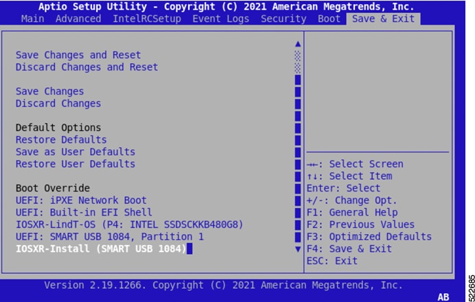
|
||
|
Step 9 |
Choose IOS -XR Install. The BIOS UI displays the USB drive vendor in the brackets, in this case, SMART USB 1084. The system detects USB and boots the image from USB. |
||
|
Step 10 |
Remove the USB drive after the
|
DHCP Configuration
DHCP configuration is required for both manual configuration and ZTP configuration. Follow the below sections to set up DHCP for booting NCS 1010 using ZTP and iPXE.
Introduction to DHCP Relay
A DHCP relay agent is a host that forwards DHCP packets between clients and servers that do not reside on a shared physical subnet. Relay agent forwarding is distinct from the normal forwarding of an IP router where IP datagrams are switched between networks transparently.
DHCP clients use User Datagram Protocol (UDP) broadcasts to send DHCPDISCOVER messages when they lack information about the network to which they belong.
If a client is on a network segment that does not include a server, a relay agent is needed on that network segment to ensure that DHCP packets reach the servers on another network segment. UDP broadcast packets are not forwarded, because most routers are not configured to forward broadcast traffic. You can configure a DHCP relay agent to forward DHCP packets to a remote server by configuring a DHCP relay profile and configure one or more helper addresses in it. You can assign the profile to an interface or a VRF.
The figure below demonstrates the process. The DHCP client broadcasts a request for an IP address and additional configuration parameters on its local LAN. Acting as a DHCP relay agent, Router B picks up the broadcast, changes the destination address to the DHCP server's address and sends the message out on another interface. The relay agent inserts the IP address of the interface, on which the DHCP client’s packets are received into the gateway address (giaddr) field of the DHCP packet, which enables the DHCP server to determine which subnet should receive the offer and identify the appropriate IP address range. The relay agent unicasts the messages to the server address, in this case 172.16.1.2 (which is specified by the helper address in the relay profile).

Prerequisites for Configuring DHCP Relay Agent
The following are the prerequisites to configure a DHCP relay agent:
-
You must be in a user group associated with a task group that includes the proper task IDs. The command reference guides include the task IDs required for each command. If you suspect user group assignment is preventing you from using a command, contact your AAA administrator for assistance.
-
A configured and running DHCP client and DHCP server.
-
Connectivity between the relay agent and DHCP server
Limitations for DHCP Relay Feature
These are the limitations for implementing DHCP relay feature:
-
The multicast addresses are not supported. The helper-address command in DHCP relay profile submode supports valid unicast IP address as the helper address.

Note
Configuring the helper-address command directly (not using profile) under a interface (such as BVI interface) is not supported.
-
Only interface-id and remote-id DHCP option code are added by a relay agent while forwarding the packet to a DHCP server.
Note
Configuring DHCP option code is not supported in DHCP relay profile submode.
Configuring and Enabling the DHCP Relay Agent
Configuration Example
RP/0/RP0/CPU0:ios# configure
RP/0/RP0/CPU0:ios(config)# dhcp ipv4
RP/0/RP0/CPU0:ios(config-dhcpv4)# profile r1 relay
RP/0/RP0/CPU0:ios(config-dhcpv4-relay-profile)#  helper-address vrf default 198.51.100.1 giaddr 198.51.100.3
RP/0/RP0/CPU0:ios(config-dhcpv4-relay-profile)# !
RP/0/RP0/CPU0:ios(config-dhcpv4-relay-profile)# interface GigabitEthernet0/0/0/2 relay profile r1
RP/0/RP0/CPU0:ios(config-dhcpv4)# commit
Running Configuration
RP/0/RP0/CPU0:ios# show running-config dhcp ipv4
Tue Aug 29 07:30:50.677 UTC
dhcp ipv4
 profile r1 relay
  helper-address vrf default 198.51.100.1 giaddr 198.51.100.3
 !
 interface GigabitEthernet0/0/0/2 relay profile r1
!
DHCP Client
The Dynamic Host Configuration Protocol (DHCP) client functionality enables the router interfaces to dynamically acquire the IPv4 or DHCPv4 or DHCPv6 server, and forwards the responses back to the correct Layer 2 address so that the correct device gets the correct configuration information.
DHCP has the ability to allocate IP addresses only for a configurable period of time, called the lease period. If the client is required to retain this IP address for a longer period beyond the lease period, the lease period must be renewed before the IP address expires. The client renews the lease based on configuration that was sent from the server. The client unicasts a REQUEST message using the IP address of the server. When a server receives the REQUEST message and responds with an ACK message. The lease period of the client is extended by the lease time configured in the ACK message.
Enabling DHCP Client on an Interface
You can enable both the DHCPv4 and DHCPv6 clients at an interface level. The DHCP component receives a notification when DHCPv4 or DHCPv6 is enabled or disabled on an interface.
RP/0/RP0/CPU0:ios# configure
Tue Aug 29 09:26:12.468 UTC
RP/0/RP0/CPU0:ios(config)# int mgmtEth 0/RP0/CPU0/0
RP/0/RP0/CPU0:ios(config-if)# ipv4 address dhcp
RP/0/RP0/CPU0:ios(config-if)# commit
Tue Aug 29 09:26:21.715 UTC
RP/0/RP0/CPU0:ios(config-if)# exit
RP/0/RP0/CPU0:ios(config)# int mgmtEth 0/RP0/CPU0/0
RP/0/RP0/CPU0:ios(config-if)# ipv6 address dhcp
dhcp  dhcp-client-options
RP/0/RP0/CPU0:ios(config-if)# ipv6 address dhcp
RP/0/RP0/CPU0:ios(config-if)# commit
Tue Aug 29 09:26:50.159 UTC
Boot Using iPXE
iPXE is a pre-boot execution environment that is included in the network card of the management interfaces and works at the system firmware (UEFI) level of the chassis. iPXE is used to reimage the system, and boot the chassis in case of boot failure or in the absence of a valid bootable partition. iPXE downloads the ISO image, proceeds with the installation of the image, and finally bootstraps inside the new installation.
Note |
The time taken for iPXE to download the ISO image depends on the network speed. Ensure that the network speed is sufficient to complete the image download in less than 10 minutes. The chassis reloads if the image is not downloaded by 10 minutes. |
iPXE acts as a bootloader and provides the flexibility to choose the image that the system will boot based on the Platform Identifier (PID), the Serial Number, or the management MAC-address. You must define iPXE in the DHCP server configuration file.
Note |
To initiate the iPXE boot process, perform one of the following methods:
|
Setup DHCP Server
A DHCP server must be configured for IPv4, IPv6, or both communication protocols.
Note |
For DHCPv6, a routing advertisement (RA) message must be sent to all nodes in the network that indicates which method is to be used to obtain the IPv6 address. Configure Router-advertise-daemon (radvd, install using yum install radvd) to allow the client to send the DHCP request. For example: |
To setup a DHCP server:
-
Create the
dhcpd.conffile (for IPv4, IPv6 or both communication protocols),dhcpv6.conffile (for IPv6) or both in the /etc/ directory. This configuration file stores the network information such as the path to the script, location of the ISO install file, location of the provisioning configuration file, serial number, MAC address of the chassis. -
Test the server once the DHCP server is running:
For example, for ipv4:
-
Use MAC address of the chassis: Ensure that the above configuration is successful.host ncs1010 { hardware ethernet ab:cd:ef:01:23:45; fixed-address <ip address>; filename "http://<httpserver-address>/<path-to-image>/ncs1010-mini-x.iso"; } -
Use serial number of the chassis: host demo { option dhcp-client-identifier "<chassis-serial-number>"; filename "http://<IP-address>/<hardware-platform>-mini-x.iso"; fixed-address <IP-address>; }The serial number of the chassis is derived from the BIOS and is used as an identifier.
Example host 10.89.205.202 { hardware ethernet 40:55:39:56:0c:e8; option dhcp-client-identifier "<FCB2437B066>"; if exists user-class and option user-class = "iPXE" { filename "http://10.89.205.127/box1/ncs1010-x64.iso"; } else { filename "http://10.89.205.127/box1/StartupConfig.cfg"; } fixed-address 10.89.205.202; }
-
Boot Using iPXE
Before you use the iPXE boot, ensure that:
-
DHCP server is set and is running.
-
Management port of the NCS 1010 chassis is in UP state.
Use anyone of the following methods to invoke the iPXE boot process:
-
via CLI terminal:
Run the following command to invoke the iPXE boot process to reimage the chassis: reload bootmedia network location allExample: RP/0/RP0/CPU0:ios# reload bootmedia network location all Wed Jul 6 15:11:33.791 UTC Reload hardware module ? [confirm]The following example shows the output of the command: Preparing system for backup. This may take a few minutes especially for large configurations. Status report: node0_RP0_CPU0: BACKUP INPROGRESS RP/0/RP0/CPU0:P1D_DT# Status report: node0_RP0_CPU0: BACKUP HAS COMPLETED SUCCESSFULLY [Done] [FAILED] Failed unmounting /mnt/fuse/parser_server. [ OK ] Unmounted /mnt/fuse/ftp. [ OK ] Unmounted /mnt/fuse/nvgen_server. [ OK ] Unmounted /boot/efi. [ OK ] Unmounted /selinux. . . Output Snipped . . .. *** Sirius *** System Initializing.. .. ERROR: Class:0; Subclass:10000; Operation: 1004 Shelf Assembly Reset Shelf Assembly Reset for P1 .. *** Sirius *** System Initializing.. .. ERROR: Class:0; Subclass:10000; Operation: 1004 . . Output Snipped . . NCS1010, Initializing Devices Booting from Primary Flash Aldrin: Programmed MI 10 . . Output Snipped . . Version 2.19.1266. Copyright (C) 2022 American Megatrends, Inc. BIOS Date: 05/20/2022 10:47:39 Ver: 0ACHI0410 Press <DEL> or <ESC> to enter setup. TAM Chipguard Validate Observed DB Error: 0x48 WARNING!!! TAM: Empty Chip DB Software Boot OK, Validated iPXE initialising devices...ok iPXE 1.0.0+ (c2215) -- Open Source Network Boot Firmware -- http://ipxe.org Features: DNS HTTP TFTP VLAN EFI ISO9660 ISO9660_grub Menu Trying net0-2051,net0-2052 and net0-2053... net0-2051: 68:9e:0b:b8:71:1e using NII on NII-PCI06:00.0 (open) [Link:down, TX:0 TXE:0 RX:0 RXE:0] [Link status: Unknown (http://ipxe.org/1a086194)] Configuring (net0-2051 68:9e:0b:b8:71:1e).................. Error 0x040ee186 (http://ipxe.org/040ee186) net0-2052: 68:9e:0b:b8:71:1f using NII on NII-PCI06:00.0 (open) [Link:up, TX:0 TXE:0 RX:18 RXE:14] [RXE: 8 x "Operation not supported (http://ipxe.org/3c086083)"] [RXE: 3 x "Error 0x440e6083 (http://ipxe.org/440e6083)"] [RXE: 3 x "The socket is not connected (http://ipxe.org/380f6093)"] Configuring (net0-2052 68:9e:0b:b8:71:1f).................. ok net0: fe80::6a9e:bff:feb8:711e/64 net1: fe80::6a9e:bff:feb8:7121/64 (inaccessible) net2: fe80::6a9e:bff:feb8:7122/64 (inaccessible) net3: fe80::6a9e:bff:feb8:7123/64 (inaccessible) net0-2051: fe80::6a9e:bff:feb8:711e/64 net0-2051: 2001:420:5446:2014::281:0/119 gw fe80::676:b0ff:fed8:c100 (no address) net0-2051: 2002:420:54ff:93:6a9e:bff:feb8:711e/64 gw fe80::fa4f:57ff:fe72:a640 net0-2052: 10.4.33.44/255.255.0.0 gw 10.4.33.1 net0-2052: fe80::6a9e:bff:feb8:711e/64 net0-2053: fe80::6a9e:bff:feb8:711e/64 Filename: http://10.4.33.51/P1D_DT_05/ncs1010-x64.iso http://10.4.33.51/P1D_DT_05/ncs1010-x64.iso... ok . . Output Snipped . . User Access Verification Username: cisco Password: -
via BIOS interface:
-
Reboot NCS 1010 using power cycle or console.
-
Press Esc to enter BIOS.
-
Select the Save & Exit tab of BIOS.
-
Choose UEFI: iPXE Network Boot.
The following example shows the output of the command: Preparing system for backup. This may take a few minutes especially for large configurations. Status report: node0_RP0_CPU0: BACKUP INPROGRESS RP/0/RP0/CPU0:P1D_DT# Status report: node0_RP0_CPU0: BACKUP HAS COMPLETED SUCCESSFULLY [Done] [FAILED] Failed unmounting /mnt/fuse/parser_server. [ OK ] Unmounted /mnt/fuse/ftp. [ OK ] Unmounted /mnt/fuse/nvgen_server. [ OK ] Unmounted /boot/efi. [ OK ] Unmounted /selinux. . . Output Snipped . . .. *** Sirius *** System Initializing.. .. ERROR: Class:0; Subclass:10000; Operation: 1004 Shelf Assembly Reset Shelf Assembly Reset for P1 .. *** Sirius *** System Initializing.. .. ERROR: Class:0; Subclass:10000; Operation: 1004 . . Output Snipped . . NCS1010, Initializing Devices Booting from Primary Flash Aldrin: Programmed MI 10 . . Output Snipped . . Version 2.19.1266. Copyright (C) 2022 American Megatrends, Inc. BIOS Date: 05/20/2022 10:47:39 Ver: 0ACHI0410 Press <DEL> or <ESC> to enter setup. TAM Chipguard Validate Observed DB Error: 0x48 WARNING!!! TAM: Empty Chip DB Software Boot OK, Validated iPXE initialising devices...ok iPXE 1.0.0+ (c2215) -- Open Source Network Boot Firmware -- http://ipxe.org Features: DNS HTTP TFTP VLAN EFI ISO9660 ISO9660_grub Menu Trying net0-2051,net0-2052 and net0-2053... net0-2051: 68:9e:0b:b8:71:1e using NII on NII-PCI06:00.0 (open) [Link:down, TX:0 TXE:0 RX:0 RXE:0] [Link status: Unknown (http://ipxe.org/1a086194)] Configuring (net0-2051 68:9e:0b:b8:71:1e).................. Error 0x040ee186 (http://ipxe.org/040ee186) net0-2052: 68:9e:0b:b8:71:1f using NII on NII-PCI06:00.0 (open) [Link:up, TX:0 TXE:0 RX:18 RXE:14] [RXE: 8 x "Operation not supported (http://ipxe.org/3c086083)"] [RXE: 3 x "Error 0x440e6083 (http://ipxe.org/440e6083)"] [RXE: 3 x "The socket is not connected (http://ipxe.org/380f6093)"] Configuring (net0-2052 68:9e:0b:b8:71:1f).................. ok net0: fe80::6a9e:bff:feb8:711e/64 net1: fe80::6a9e:bff:feb8:7121/64 (inaccessible) net2: fe80::6a9e:bff:feb8:7122/64 (inaccessible) net3: fe80::6a9e:bff:feb8:7123/64 (inaccessible) net0-2051: fe80::6a9e:bff:feb8:711e/64 net0-2051: 2001:420:5446:2014::281:0/119 gw fe80::676:b0ff:fed8:c100 (no address) net0-2051: 2002:420:54ff:93:6a9e:bff:feb8:711e/64 gw fe80::fa4f:57ff:fe72:a640 net0-2052: 10.4.33.44/255.255.0.0 gw 10.4.33.1 net0-2052: fe80::6a9e:bff:feb8:711e/64 net0-2053: fe80::6a9e:bff:feb8:711e/64 Filename: http://10.4.33.51/P1D_DT_05/ncs1010-x64.iso http://10.4.33.51/P1D_DT_05/ncs1010-x64.iso... ok . . Output Snipped . . User Access Verification Username: cisco Password:
-
Boot Using Zero Touch Provisioning
ZTP allows you to provision the network device with day 0 configurations and supports both management ports and data ports.
ZTP provides multiple options, such as:
-
Automatically apply specific configuration in a large-scale environment.
-
Download and install specific IOS XR image.
-
Install specific application package or third party applications automatically.
-
Deploy containers without manual intervention.
-
Upgrade or downgrade software versions effortlessly on thousands of network devices at a time
ZTP helps you manage large-scale service providers infrastructures effortlessly. Following are the added benefits of using ZTP:
-
ZTP helps you to remotely provision a router anywhere in the network. Thus eliminates the need to send an expert to deploy network devices and reduces IT cost.
-
Automated provisioning using ZTP can remove delay and increase accuracy and thus is cost-effective and provides better customer experience.
By automating repeated tasks, ZTP allows network administrators to concentrate on more important stuff.
-
ZTP process helps you to quickly restore service. Rather than troubleshooting an issue by hand, you can reset a system to well-known working status.
Prerequisites:
ZTP does not execute, if a username is already configured in the system.
ZTP is initiated in one of the following ways:
-
Automated Fresh Boot:
Fresh Boot: When you boot the device, the ZTP process initiates automatically if the device does not have a prior configuration. During the process, the router receives the details of the configuration file from the DHCP server. Use this method for devices that has no pre-loaded configuration. See Fresh Boot Using DHCP.
You must define the configuration file or the bootscript that is downloaded from the DHCP server:
-
Configuration File: The first line of the file must contain !! IOS XR configuration", to process the file as a configuration. If you are trying to bring up ten new nodes, you have to define ten configuration files. See Build your Configuration File.
-
ZTP Bootscript: Define the script to be executed on every boot. See Configure ZTP BootScript .
-
Manual Invocation using CLI: Use this method when you want to forcefully initiate ZTP on a fully configured device, using CLI. See Invoke ZTP Manually through CLI.
Fresh Boot Using DHCP
The ZTP process initiates when you boot the network-device with an IOS-XR image. The process starts only on the device that doesn't have a prior configuration.
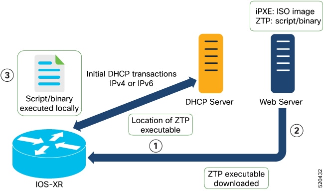
This image depicts the high-level work flow of the ZTP process:
-
ZTP sends DHCP request to fetch the ZTP configuration file or user script. To help the Bootstrap server uniquely identify the device, ZTP sends below DHCP option.
-
DHCP(v4/v6) client-id=Serial Number
-
DHCPv4 option 124: Vendor, Platform, Serial-Number
-
DHCPv6 option 16: Vendor, Platform, Serial-Number
The following is the default sequential flow of the ZTP process:
-
ZTP sends IPv4 DHCP request first on all the management port. In case there is a failure, then ZTP sends IPv6 DHCP request on all the management port.
-
ZTP sends IPv4 DHCP request first on all the data port. In case there is a failure, then ZTP sends IPv6 DHCP request on all the data port.
The default sequential flow is defined in configuration file and you can modify the sequence using the configuration file.
-
- DHCP server identifies the device and responds with DHCP response using one of the following options:
DHCP server should be configured to respond with the DHCP options.
-
DHCPv4 using BOOTP filename to supply script/config location.
-
DHCPv4 using Option 67 (bootfile-name) to supply script/config location.
-
DHCPv6 using Option 59 (OPT_BOOTFILE_URL) to supply script/config location
-
-
The network device downloads the file from the web server using the URL location that is provided in the DHCP response.
-
The device receives a configuration file or script file from the HTTP server.
Note
-
If the downloaded file content starts with !! IOS XR it is considered as a configuration file.
-
If the downloaded file content starts with #! /bin/bash, #! /bin/sh or #!/usr/bin/python it is considered as a script file.
-
-
The device applies the configuration file or executes the script or binary in the default bash shell.
-
The Network device is now up and running.
Build your Configuration File
Based on the business need, you can use a configuration or script file to initiate the ZTP process.
The configuration file content starts with !! IOS XR.
The following is the sample configuration file. You can automate all the configurations. For more information on creating ZTP configuration file, refer ZTP Configuration Files Creation.
Tue May 4 18:08:59.544 UTC
Building configuration...
!! IOS XR Configuration 7.7.1.22I
!! Last configuration change at Tue May 4 17:12:47 2021 by cisco
!
line console
exec-timeout 0 0
!
line default
exec-timeout 0 0
session-timeout 0
!
vty-pool default 0 20
alias alarms show alarms brief system active
interface MgmtEth0/RP0/CPU0/0
ipv4 address dhcp
no shut
!
interface MgmtEth0/RP0/CPU0/1
description noshut-interface-ztp
ipv4 address 10.127.60.160 255.255.255.0
no shut
!
interface MgmtEth0/RP0/CPU0/2
description noshut-interface-ztp
no shut
!
interface PTP0/RP0/CPU0/0
description noshut-interface-ztp
no shut
Cisco NCS 1010 System Setup and Software Installation Guide, IOS XR Release 7.7.x
19
Bring-up Cisco NCS 1010
Build your Configuration File
!
telnet vrf default ipv4 server max-servers 100a
ssh server v2
ssh server netconf vrf default
netconf-yang agent
ssh
!
netconf agent tty
grpc
router static
address-family ipv4 unicast
0.0.0.0/0 10.127.60.1
end
Configure ZTP BootScript
ZTP downloads and executes the script files. These script files include a programmatic approach to complete a task. For example, scripts created using IOS XR commands to perform patch upgrades. The first line of the file must contain #! /bin/bash or #! /bin/sh for ZTP to process the file as script. You can either use the ZTP bash script or the ZTP configuration file.
You can either use the ZTP bash script or the ZTP configuration file.
If you want to hardcode a script to be executed every boot, configure the following.
Router#configure
Router(config)#ztp bootscript /disk0:/myscript
Router(config)#commit
The above configuration waits for the first data-plane interface to be configured and then wait an extra minute for the management interface to be configured with an IP address, to ensure that we have connectivity in the third-party namespace for applications to use. If the delay is not desired, use:
Router#configure
Router(config)#ztp bootscript preip /disk0:/myscript
Router(config)#commit
Note |
When the above command is first configured, you will be prompted if you wish to invoke it now. The prompt helps with testing. |
This is the example content of /disk0:/myscript:
host ncs1010_P1B_DT_08_ETH0 {
#hardware ethernet 68:9e:0b:b8:6f:5c ;
option dhcp-client-identifier "FCB2437B05N" ;
if exists user-class and option user-class = "iPXE" {
filename "http://10.33.0.51/P1B_DT_08/ncs1010-x64.iso";
} else {
filename "http://10.33.0.51/P1B_DT_08/startup.cfg";
}
fixed-address 10.33.0.19;
}
The following is the sample content of the ZTP bash script.
#! /bin/bash
#
# NCS1010 Demo Sample
# ZTP installation of config and day-0 SMU's
#
source ztp_helper

wget http://downloads.sourceforge.net/project/yourcode/application.tgz
#install the downloaded application.tgz

#Run XR CLI’s from the script
`xrcmd “show version”`
The following is the sample content of the ZTP configuration file.
Tue May 4 18:08:59.544 UTC
Building configuration...
!! IOS XR Configuration 7.7.1.22I
!! Last configuration change at Tue May 4 17:12:47 2021 by cisco
!
line console
exec-timeout 0 0
!
line default
exec-timeout 0 0
session-timeout 0
!
vty-pool default 0 20
alias alarms show alarms brief system active
interface MgmtEth0/RP0/CPU0/0
ipv4 address dhcp
no shut
!
interface MgmtEth0/RP0/CPU0/1
description noshut-interface-ztp
ipv4 address 10.127.60.160 255.255.255.0
no shut
!
interface MgmtEth0/RP0/CPU0/2
description noshut-interface-ztp
no shut
!
interface PTP0/RP0/CPU0/0
description noshut-interface-ztp
no shut
!
interface PTP0/RP0/CPU0/1
description noshut-interface-ztp
no shut
end
Invoke ZTP Manually through CLI
Manual ZTP can be invoked through CLI commands. This manual way helps you to provision the router in stages. Ideal for testing out ZTP configuration without a reboot. If you want to invoke a ZTP on an interface (data ports or management port), you don't have to bring up and configure the interface first. You can execute the ztp initiate command, even if the interface is down, ZTP script brings it up and invoke dhclient. So ZTP could run over all interfaces no matter it is up or down.
Use the ztp initiate, ztp terminate, and ztp clean commands to force ZTP to run over more interfaces.
-
ztp initiate—Invokes a new ZTP DHCP session. Logs can be found in /disk0:/ztp/ztp.log.
-
ztp terminate—Terminates any ZTP session in progress.
-
ztp clean—Removes only the ZTP state files.
The log file ztp.log is saved in /var/log/ztp.log folder, and a copy of log file is available at /disk0:/ztp/ztp.log location using a soft link. However, executing ztp clean clears files saved on disk and not on /var/logztp.log folder where current ZTP logs are saved. In order to have a log from current ZTP run, you must manually clear the ZTP log file from /var/log/ztp.log folder.
Procedure
|
Step 1 |
(optional) ztp clean Example: Removes all the ZTP logs and saved settings. |
|
Step 2 |
ztp initiate Example: Use the show logging command or see the /var/log/ztp.log to check progress. Reboots the Cisco NCS 1010 system. |
|
Step 3 |
(Optional) ztp terminate Example: Terminates the ZTP process. |
Invoke ZTP Through Reload
Procedure
|
Step 1 |
configure Example: Enters the configuration mode. |
|
Step 2 |
commit replace Example: Removes the entire running configuration. |
|
Step 3 |
ztp clean Example: Removes all the ZTP logs and saved settings. |
|
Step 4 |
reload Example: After the node comes up, you can check that the ZTP is initiated and the configuration has been restored successfully. Reboots the Cisco NCS 1010 system. |
ZTP Logging
ZTP logs its operation on the flash file system in the directory /disk0:/ztp/. ZTP logs all the transaction with the DHCP server and all the state transition.
The following example displays the execution of a simple configuration script downloaded from a data interface using the command ztp initiate interface Ten 0/0/0/0 verbose, this script unshuts all the interfaces of the system and configure a load interval of 30 seconds on all of them.
2022-06-17 11:52:34,682  19292 [Xr           ] INF: Downloading the file to /tmp/ztp.script
2022-06-17 11:52:35,329  19292 [Report       ] INF: User script downloaded successfully. Provisioning in progress.
2022-06-17 11:52:35,330  19292 [Engine       ] DEB: ZAdmin, current state:active. Processing work: Config device work for ZAdmin. done = False
2022-06-17 11:52:35,330  19292 [ZAdmin       ] DEB: Proceeding to provision the router
2022-06-17 11:52:35,331  19292 [Engine       ] DEB: ZAdmin, current state:active. Processing work: ZAdmin: Apply configuration. done = False
2022-06-17 11:52:35,331  19292 [Engine       ] INF: ZAdmin, current state:active: state tag changed to provision
RP/0/RP0/CPU0:Jun 17 11:52:35.341 UTC: pyztp2[140]: %INFRA-ZTP-4-CONFIG_INITIATED : ZTP has initiated config load and commit operations
2022-06-17 11:52:35,339  19292 [Env          ] DEB: No MTU configs detected
2022-06-17 11:52:35,340  19292 [Engine       ] DEB: ZAdmin, current state:active. Processing work: ZAdmin: Apply configuration. done = False
2022-06-17 11:52:35,354  19292 [Xr           ] DEB: Will apply the following config: /disk0:/ztp/customer/config.candidate
2022-06-17 11:52:35,354  19292 [Xr           ] INF: Applying user configurations
2022-06-17 11:52:35,355  19292 [Configuration] INF: Provisioning via config replace
2022-06-17 11:52:54,656  19292 [Configuration] INF: Configuration has been applied
2022-06-17 11:52:54,656  19292 [Engine       ] DEB: ZAdmin, current state:active. Processing work: Sending standby sync message. done = False
2022-06-17 11:52:54,663  19292 [Engine       ] DEB: ZAdmin, current state:active. Processing work: [privileged] getting engine status. done = False
2022-06-17 11:52:54,664  19292 [Engine       ] DEB: ZAdmin, current state:active. Processing work: ZAdmin: Execute post-configuration script. done = False
2022-06-17 11:52:55,212  19292 [Env          ] INF: Env::cleanup, success:True, exiting:False
2022-06-17 11:52:55,213  19292 [ZtpHelpers   ] DEB: Executing: source /pkg/bin/ztp_helper.sh && echo -ne  | xrcmd "show running-config"
2022-06-17 11:52:55,825  19292 [Env          ] INF: Executing command ip netns exec vrf-default /sbin/dhclient -4 -cf /etc/dhcp/dhclient.conf.ztp -lf /var/lib/dhcp/dhclient.leases.ztp -sf /etc/dhcp/dhclient-script.ztp2 -r Mg0_RP0_CPU0_0 to release IP
2022-06-17 11:52:56,968  19292 [Xr           ] INF: Removing linux route with ip 10.33.0.63
2022-06-17 11:52:57,023  19292 [Engine       ] INF: ZAdmin, current state:active, exit code:success
2022-06-17 11:52:57,023  19292 [Engine       ] INF: ZAdmin, current state:final, exit code:success: state changed to final
2022-06-17 11:52:59,737  19292 [Engine       ] DEB: ZAdmin, current state:final, exit code:success. Processing work: Sending standby sync message. done = False
2022-06-17 11:52:59,738  19292 [Engine       ] WAR: ZAdmin, current state:final, exit code:success: work is ignored: work=<desc='Sending standby sync message' done=False priv=False>
2022-06-17 11:52:59,738  19292 [Engine       ] DEB: ZAdmin, current state:final, exit code:success. Processing work: [privileged] getting engine status. done = False
2022-06-17 11:53:04,744  19292 [main     ] DEB: Moved to final state
2022-06-17 11:53:04,745  19292 [main     ] DEB: ZTP completed successfully
2022-06-17 11:53:04,745  19292 [main     ] INF: Exiting SUCCESSFULLY
2022-06-17 11:53:04,746  19292 [main     ] DEB: Exiting. Will not retry now.
2022-06-17 11:53:04,746  19292 [main     ] DEB: Shutting down adaptor. Cleanup False. Exiting False
2022-06-17 11:53:04,748  19292 [Engine       ] DEB: ZAdmin, current state:final, exit code:success. Processing work: [privileged] prepare engine shutdown. done = False
2022-06-17 11:53:04,849  19292 [Engine       ] DEB: ZAdmin, current state:final, exit code:success. Processing work: [privileged] shutting down ZAdmin engine. done = False
2022-06-17 11:53:04,849  19292 [Engine       ] INF: ZAdmin, current state:final, exit code:shutdown
2022-06-17 11:53:04,849  19292 [Engine       ] INF: ZAdmin, exit code:shutdown: state changed to None
2022-06-17 11:53:04,849  19292 [Engine       ] DEB: ZAdmin, exit code:shutdown: breaking engine loop after shutdown
2022-06-17 11:53:04,850  19292 [Engine       ] DEB: ZAdmin, exit code:shutdown: end of event loop
2022-06-17 11:53:04,850  19292 [Adaptor      ] DEB: Adaptor : Cleanup for admin context on Terminate
2022-06-17 11:53:06,119  19292 [main     ] INF: Exiting SUCCESSFULLY
2022-06-17 11:53:06,119  19292 [main     ] INF: ZTP Exited
RP/0/RP0/CPU0:Jun 17 11:53:06.119 UTC: pyztp2[140]: %INFRA-ZTP-4-EXITED : ZTP exited
Generate Tech Support Information for ZTP
When you have a problem in the ztp process that you cannot resolve, the resource of last resort is your Cisco Systems technical support representative. To analyze a problem, your technical support representative needs certain information about the situation and the symptoms that you are experiencing. To speed up the problem isolation and resolution process, collect the necessary data before you contact your representative.
Use the show tech-support ztp command to collect all debugging information of ztp process.
Example:
RP/0/RP0/CPU0:R1#show tech-support ztp
Thu Jul 28 08:33:27.531 UTC
++ Show tech start time: 2022-Jul-28.083327.UTC ++
Thu Jul 28 08:33:28 UTC 2022 Waiting for gathering to complete
..
Thu Jul 28 08:33:34 UTC 2022 Compressing show tech output
Show tech output available at 0/RP0/CPU0 : /harddisk:/showtech/showtech-R1-ZTP-2022-Jul-28.083327.UTC.tgz
++ Show tech end time: 2022-Jul-28.083334.UTC ++
RP/0/RP0/CPU0:R1#
In the above example, the tech support information is saved as .tgz file in the specified location. This information can be shared with the Cisco Technical Support representatives for troubleshooting the ztp process.
 Feedback