Daisy Chain

This chapter describes the Daisy Chain optical application for Cisco NCS 1010.

Daisy Chain Overview

Table 1. Feature History

Feature Name

Release Information

Description

Daisy Chain on NCS 1010 Management Ports

Cisco IOS XR Release 7.10.1

You can now connect NCS 1010 devices in a Daisy Chain topology. Here multiple NCS 1010 devices are connected to form a ring-like topology, and only the first and last nodes are connected to a Top-of-Rack (TOR) switch, thereby reducing the number of connections.

The Daisy Chain topology also provides more redundancy as data is transmitted in both directions. The first connection acts as a primary path and carries the traffic whereas the last connection acts as a secondary path. In case the primary path fails, the secondary path serves as its backup for data transmission and allows traffic to continue to transmit in the network.

The daisy chain arrangement allows multiple NCS 1010 nodes to be connected to each other in a ring, where only the first and the last nodes are connected to a TOR switch. The switch allows management of all the NCS 1010 devices in the network and also prevents traffic storm. The data transmitted over the network passes through each node in the ring until it reaches the destination node. This arrangement allows the switch to send data in both directions and prevents one node failure from cutting off certain network parts.

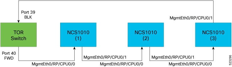
The following diagram shows the Daisy Chain topology where three NCS 1010 nodes are connected to each other over the management ports 0 and 1.

Figure 1. NCS 1010 in a Daisy Chain Network

Configure Daisy Chain on Management Ports

Before you begin

The following prerequisites must be met before configuring Daisy Chain on NCS1010:

  • Enable Storm Control on Switch.

  • STP must be running on the TOR switch.

  • Daisy chain must be enabled on all the NCS1010 devices in the topology.

Configuring Daisy Chain on managements ports of NCS 1010 devices involves the following tasks:

Example

The following example shows how to configure IP address on management port 0 of NCS1010 device:

RP/10/RP0:ios(config-if)#int mgmtEth 0/RP0/CPU0/0
RP/10/RP0:ios(config-if)#no shut
RP/10/RP0:ios(config-if)#ipv4 address 192.0.2.1 255.255.255.0

Configure Daisy Chain

configure

interface type Rack/Slot/Instance/Port

no ipv4 address

no ipv6 address

bridge-port routed-interface typeRack/Slot/Instance/Port

Example 1

The following example shows how to configure daisy chain on management port 1 of NCS1010 device:

RP/0/RP0:ios(config)# configure
RP/0/RP0:switch(config)# interface mgmtEth0/RP0/CPU0/1
RP/10/RP0:ios(config-if)#no ipv4 address
RP/10/RP0:ios(config-if)#no ipv6 address
RP/10/RP0:ios(config-if)#bridge-port routed-interface mgmtEth 0/RP0/CPU0/0
RP/10/RP0:ios(config-if)#commit

Example 2

The following example shows how to configure daisy chain on management port 2 of NCS1010 device:

RP/0/RP0:switch(config)# configure
RP/0/RP0:switch(config)# interface mgmtEth0/RP0/CPU0/2
RP/10/RP0:ios(config-if)#no ipv4 address
RP/10/RP0:ios(config-if)#no ipv6 address
RP/10/RP0:ios(config-if)#bridge-port routed-interface mgmtEth 0/RP0/CPU0/0
RP/10/RP0:ios(config-if)#commit

Note


Daisy chain can be extended to remote node using UDC port and OSC should be active with remote node.


Restriction


LLDP and CDP is not supported on the management port if Daisy Chain is configured​.


Verify Daisy Chain

To verify daisy chain configuration on management ports of NCS1010 device, use these commands:

show running-config interfacetype

Example

RP/0/RP0/CPU0:P2B_DT_02#show running-config interface mgmtEth
Wed Jun  7 12:44:43.673 IST
interface MgmtEth0/RP0/CPU0/0
 ipv4 address 192.0.2.1 255.255.0.0
!
interface MgmtEth0/RP0/CPU0/1
 bridge-port routed-interface MgmtEth0/RP0/CPU0/0
!
interface MgmtEth0/RP0/CPU0/2
 bridge-port routed-interface MgmtEth0/RP0/CPU0/0
!

Enable Storm Control on TOR Switch

When a large number of packets are broadcasted in a short time frame, it results in a traffic storm on a network. In a Daisy Chain network, excessive packet transmission by nodes and subsequent rebroadcasting by other nodes can lead to a traffic storm, overburdening the network.

In the Daisy Chain configuration, data can be transmitted in both directions. One of the Top of the Rack (TOR) switch ports is in the Forward state and carries the traffic whereas the other port is in the Blocked state. Three consecutive hello misses moves the port from Blocked to the Forwarding state.

When the NCS 1010 node reboots, the status of the port is changed from Blocked to Forwarding. Hence, a loop is created momentarily when both the TOR switch ports are in a forwarding state. This loop results in the duplication of packets on the network. To prevent this duplication, storm control must be enabled on the TOR switch.

To enable storm control on a TOR switch, use the following commands:

errdisable recovery interval value

errdisable recovery cause storm-control

Example

The following example shows how to enable storm control on a TOR switch:


RP/10/RP0:ios(config-if)#errdisable recovery interval 60​
RP/10/RP0:ios(config-if)#errdisable recovery cause storm-control

Disable DAD on Management Port

By default, IPv6 Duplicate Address Detection (DAD) is enabled on the management ports. Similar to storm control scenario, when IPv6 is configured for a management port, DAD happens due to looping in the network. Since DAD was enabled, management port will be down. In order to avoid management port being down due to momentary looping, DAD must be disabled on the management port on which daisy chain is configured.

To disable DAD on the management port, use the following commands:

configure

interface type Rack/Slot/Instance/Port

ipv6 nd dad attempts value

Example

The following is a sample configuration that disables DAD on management port 1:


RP/10/RP0:ios(config-if)#configure
RP/10/RP0:ios(config-if)#interface mgmtEth0/RP0/CPU0/1
RP/10/RP0:ios(config-if)#ipv6 nd dad attempts 1