Shipping and Receiving
The chassis is shipped in one of the following ways:
-
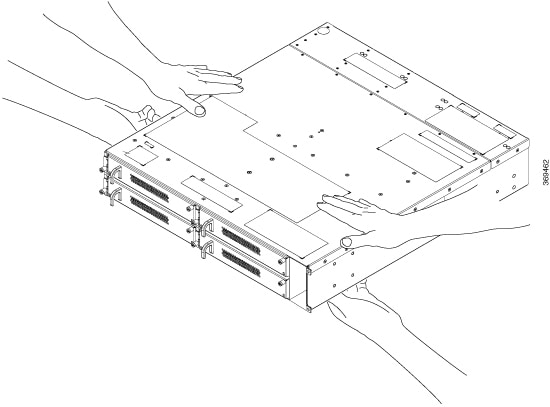
Chassis with filler cards and line cards— you receive the chassis with preinstalled line cards (based on the number of line cards you have ordered) and the rest of the line card slots have filler cards. If you have preordered four line cards, then, the chassis does not contain any filler cards. There are four fiber management brackets in the package, for each of the line card or filler cards preinstalled in the chassis. The controller and the three fan units are also preinstalled. The other items available in the same package (with the chassis) are: -
Accessory kit, that has all the installation hardware.
-
Spare Serial Number label.
-
Two PSUs - AC or DC. Installation of PSUs is discussed in the Installation of Modules chapter.
AC chassis - while ordering for an AC chassis, select the power cable. Based on your choice (NEMA or CEE), you get a pair of 90 degree and straight cables for each PSU. All the AC cables are 4.25 m long.
Table 1. Power cables for the chassis Type of Cable
P1 Connector
P2 Connector
CPN
Straight cable
NEMA L6-20P
IEC 60320 – C21
72-101432-01
CEE 7/7 (Europe)
IEC 60320 – C21
72-101434-01
90-degree cable
CEE 7/7 (Europe)
IEC 60320 – C21
72-101425-01
NEMA L6-20P
IEC 60320 – C21
37-1138-01
Figure 1. 90-degree Cable (CEE 7/7) 
Figure 2. 90-degree Cable (NEMA L6-20P) 
Figure 3. Straight Cable (NEMA L6-20P) 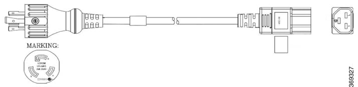
Figure 4. Straight Cable (CEE 7/7) 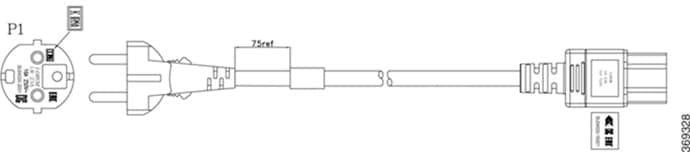

Note
The 90deg cable is used only for ETSI racks to maintain a footprint of 600 mm.
DC chassis - when you order for a DC chassis, you get four power lugs for each PSU (a pair of 90-degree and a pair of 180-degree lugs). 180-degree lugs are used for ETSI racks to maintain a footprint of 600 mm.
Figure 5. DC Power Cable Lug (180-degree) 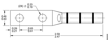
Figure 6. DC Power Cable Lug (90-degree) 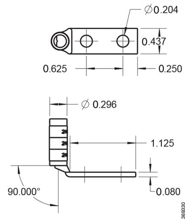
Figure 7. Breakout Cable 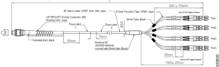
Note
The breakout cable is used only for ETSI racks to maintain a footprint of 600 mm.
Table 2. Specifications of Breakout Cables PID
CPN
MPN
Overall Length (in m)
ONS-4X10-MMCBL-5=
72-101758-01
BCJ7F3FM005CSO008
05 plus or minus 0.30
ONS-4X10-MMCBL-10=
72-101759-01
BCJ7F3FM010CSO008
10 plus or minus 0.30
ONS-4X10-MMCBL-20=
72-101760-01
BCJ7F3FM020CSO008
20 plus or minus 0.60
Figure 8. Cable with Formable Boot and Standard Boot 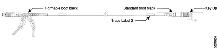
The formable boot must be used on the side of the line card.
Table 3. PIDs of Cable with Formable Boot and Standard Boot PID#
CPN#
MPN#
Overall Length (M)
-ONS-FMPO-SM-5=
72-101717-01
MDD3F 3GM005CSO001
05±0.30 m
-ONS-FMPO-SM-10=
72-101718-01
MDD3F 3GM010CSO001
10±0.30 m
-ONS-FMPO-SM-20=
72-101719-01
MDD3F 3GM020CSO001
20±0.60 m
-ONS-FMPO-SM-30=
72-101720-01
MDD3F 3GM030CSO001
30±0.90 m
-ONS-FMPO-SM-40=
72-101721-01
MDD3F 3GM040CSO001
40±1.20 m
-ONS-FMPO-SM-50=
72-101722-01
MDD3F 3GM050CSO001
50±1.50 m
-ONS-FMPO-SM-60=
72-101723-01
MDD3F 3GM060CSO001
60±1.50 m
-ONS-FMPO-SM-70=
72-101724-01
MDD3F 3GM070CSO001
70±1.50 m
-ONS-FMPO-SM-80=
72-101725-01
MDD3F 3GM080CSO001
80±1.50 m
-ONS-FMPO-SM-90=
72-101726-01
MDD3F 3GM090CSO001
90±1.50 m
-ONS-FMPO-SM-100=
72-101727-01
MDD3F 3GM100CSO001
100±1.50 m
Figure 9. Chassis shipped with Line Cards 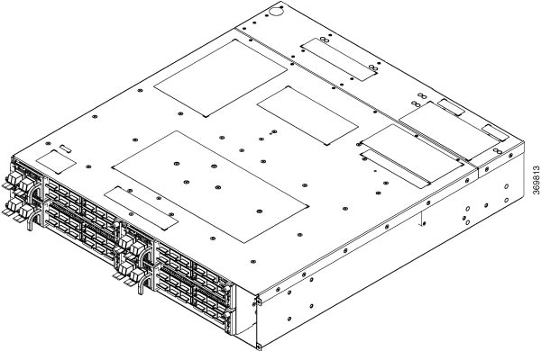
-
-
Chassis with only filler cards— you receive the chassis with four filler cards in the line card slots. There are four fiber management brackets in the package, for each of the filler cards. Each line card ordered as a spare item is shipped separately and the extra fiber management bracket (for the line card) is available in the line card package. Only the accessory kit is available with the chassis (in the same package). You must order all the other modules (fan units, controller, PSUs) separately.
For installation procedures of the modules, see Installation of Modules chapter.
Figure 10. Chassis shipped with Filler Cards 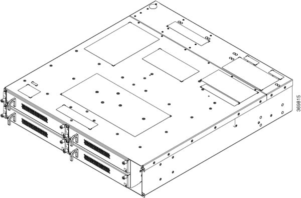
 Feedback