
Supported Controller Cards
|
Feature Name |
Release Information |
Description |
|---|---|---|
|
NCS1K4-CNTLR-B-K9 Controller Card |
Cisco IOS XR Release 7.5.1 |
NCS 1004 supports the NCS1K4-CNTLR-B-K9 controller card. The card supports a default of 9600 baud rate on the RS232 console port and runs on BIOS version 5.10. |
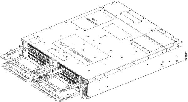
The Cisco NCS 1004 supports the following controller cards:
-
NCS1K4-CNTLR-K9
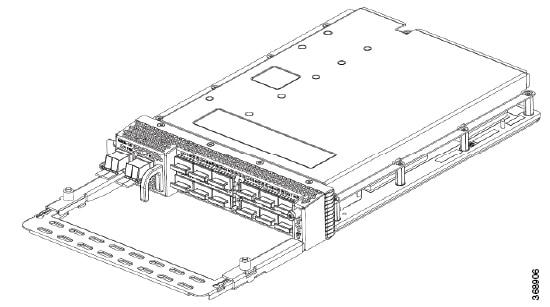
The NCS1K4-CNTLR-K9 controller card supports a default of 115200 baud rate on the RS232 console port and runs on BIOS version 4.20. The controller card has two USB 3.0, two 10/100/1000 Ethernet, one RS232 console and one SFP ports. The SFP port of the controller card supports 1GE payload.
-
NCS1K4-CNTLR-B-K9
The NCS1K4-CNTLR-B-K9 controller card supports a default of 9600 baud rate on the RS232 console port and runs on BIOS version 5.10. The controller card has two USB 3.0, two 10/100/1000 Ethernet, one RS232 console and one SFP ports. The SFP port of the controller card supports 1GE payload.
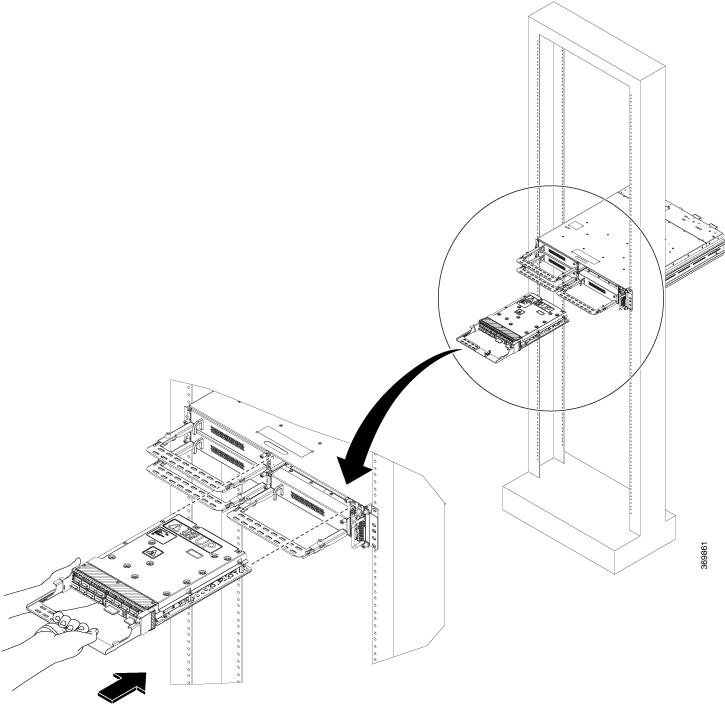
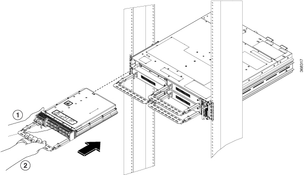
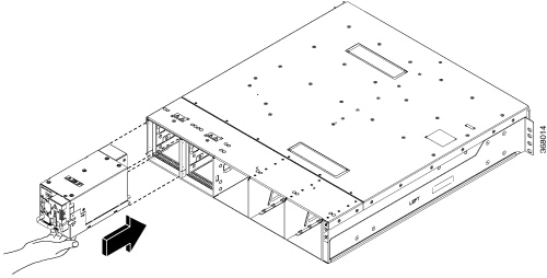
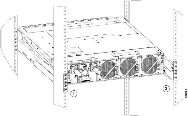
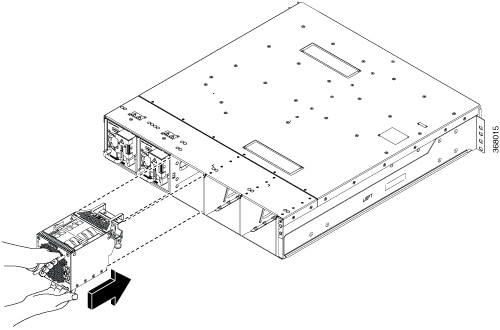
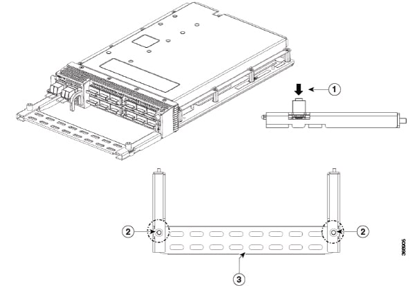
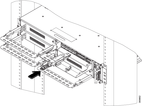
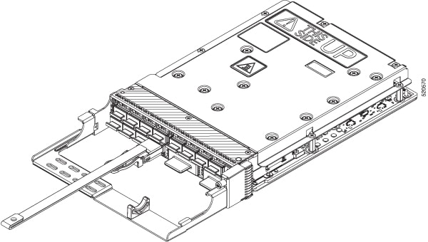
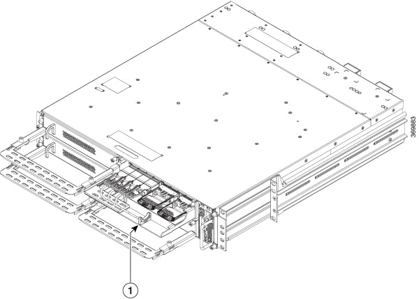
Install Controller
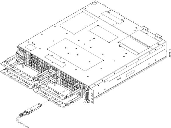
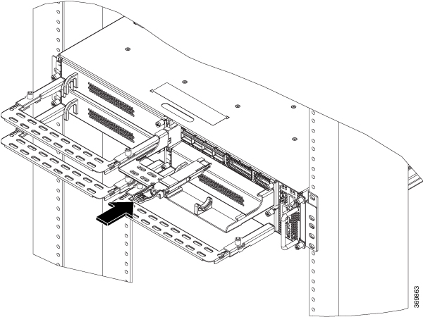
This task has information about installing the controller into the chassis.
Procedure
|
Step 1 |
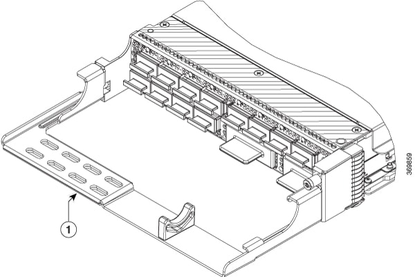
Orient the controller correctly before inserting. Check for the This Side Up label. |
|
Step 2 |
Supporting the controller at the bottom with one of your hands, slide the controller into the slot, using the handle. 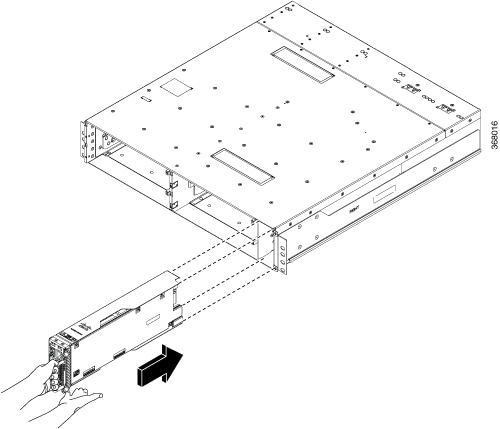 |
|
Step 3 |
Using a T15 Torx screwdriver, tighten the two M3 T15 torx screws to a torque value of 0.65 N-m. |


 Feedback