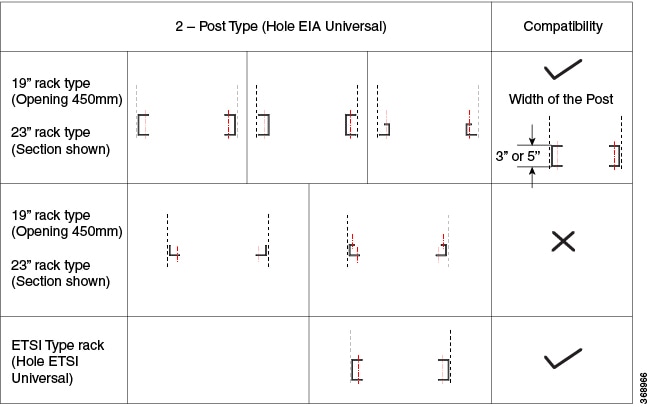
Install Cisco NCS 1004

This chapter contains procedures to install Cisco NCS 1004.

Rack Compatibility

This section provides rack compatibility details for the Cisco NCS 1004.
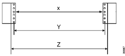
Figure 1. Four Post Rack Type
Figure 2. Four Post Rack Type

Four Post Rack Type

Figure 3. Two Post Rack Type
Figure 4. Rack Specification

Rack Type

Rack Front Opening X

Rack Mounting Hole Center-Center Y

Mounting Flange Dimension Z

19" racks

450.8mm (17.75")

465mm (18.312")

482.6mm (19")

23" racks

552.45mm (21.75")

566.7mm (22.312")

584.2mm (23")

ETSI racks

500.0mm(19.68")

515.0mm(20.276")

533.4mm(21")


Note


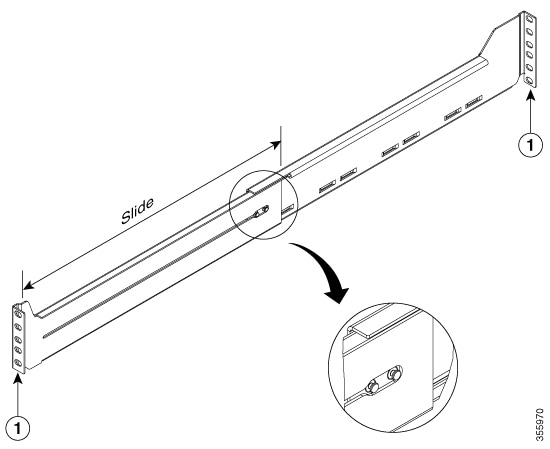
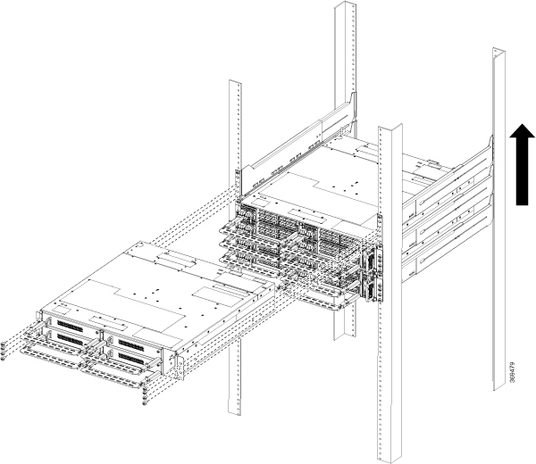
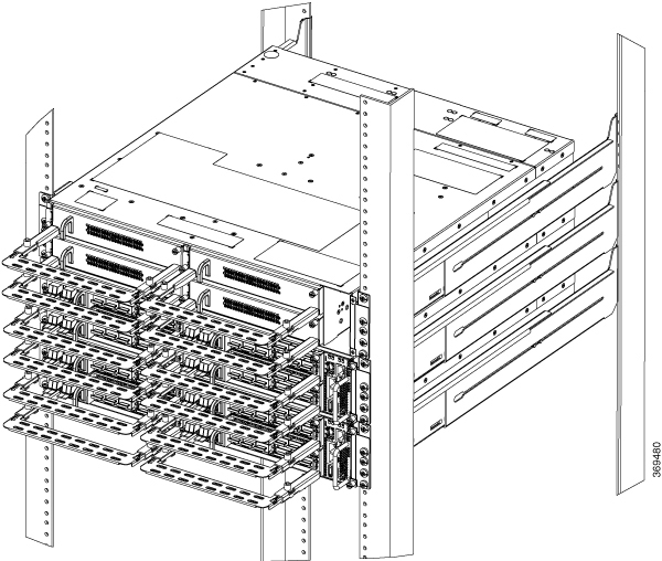
The distance between the front and the rear post in a four post rack is 427 mm (closed position) and 707 mm (open position).


Install NCS 1004 on an EIA/ANSI/ ETSI Rack


Warning


Rack Mount Instructions

The following or similar rack-mount instructions are included with the installation instructions:

  • Elevated Operating Ambient—If installed in a closed or multirack assembly, the operating temperature of the rack environment may be greater than room temperature. Therefore, consideration should be given to installing the equipment in an environment compatible with the maximum ambient temperature (Tma) specified.

  • Reduced Air Flow—Installation of the equipment in a rack should be such that the amount of air flow required for safe operation of the equipment is not compromised.

  • Mechanical Loading—Mounting of the equipment in the rack should be such that a hazardous condition is not achieved due to uneven mechanical loading.

  • Circuit Overloading—Consideration should be given to the connection of the equipment to the supply circuit and the effect that overloading of the circuits might have on overcurrent protection and supply wiring. Appropriate consideration of equipment nameplate ratings should be used when addressing this concern.

  • Reliable Earthing—Reliable earthing of rack-mounted equipment should be maintained. Particular attention should be given to supply connections other than direct connections to the branch circuit (for example, use of power strips).


It is mandatory to fix the fiber management brackets for all the cards in the chassis before installing the Cisco NCS 1004 chassis onto the rack. See Attach Fiber Management Bracket section for the detailed procedure.
Figure 5. Line Cards fitted with Fiber Management Bracket
Figure 6. Filler Cards fitted with Fiber Management Bracket

Note


In ETSI racks, to maintain a footprint of 600 mm, the cabinet door cannot be installed and the horizontal bar of the fiber management bracket should be maintained at the shortest length. See Adjusting the Fiber Management Bracket.


Caution


The sliding rail must be used only for first chassis positioning. The chassis must be fixed with screws on the front side.


Caution


Use only the fastening hardware provided with Cisco NCS 1004 to prevent loosening, deterioration, and electromechanical corrosion of the hardware and joined material.


Before you begin

Ensure the rack is compatible. See the Rack Compatibility section.

Procedure


Step 1

Attach the left and right mounting brackets to the chassis using the screws (48-2029-01) and tighten them to a torque value of 1.5 N-m.

The left and right brackets have been marked accordingly.

Figure 7. Fixing the Brackets

1

Right Bracket (700-116388-01)

2

Screws used for brackets

3

Left Bracket (700-116386-01)

Step 2

Install the four post slider or two post slider on the rack.

  1. Install Two Post Slider into an EIA/ ANSI Rack

  2. Install Four Post Slider into an EIA/ ANSI Rack

  3. Install Two Post Slider into an ETSI Rack

  4. Install Four Post Slider into an ETSI Rack

Step 3

Insert the chassis (with brackets) onto the sliders assembled on the rack.

Step 4

After the chassis is completely inserted, fasten the chassis with four screws (48-101524-01) on each side of the bracket, and using a number-2 Phillps screwdriver, tighten them to a torque value of 4.65 N-m.

See Install Air Filter for the air filter installation procedure, before you fasten the chassis to the rack.


Install Two Post Slider into an EIA/ANSI Rack

This procedure has details about installing the two post slider into an EIA/ ANSI rack.

Procedure


Step 1

Identify the two post slider and adjust the length of the slider (3" to 5").

Slide the inner sliders and adjust the length to mate with the rack surface.

Figure 8. Two Post Slider Identification

1

Check for marking on the sliders; the right and the left sliders are indicated.

Step 2

Integrate the two post slider with the rack. The procedure for 23" and 19" rack is discussed here:

  • 19" rack - the slider can be directly fitted on to a 19" rack. On the front side, insert only the top most screw of the slider (48-101524-01) and tighten it to a torque value of 4.65 N-m. On the rear side, insert three screws (48-101524-01) and tighten to a torque value of 4.65 N-m.

  • 23" rack - the slider is fitted on to a 23" rack using an adapter (refer the following image). The formed surface must always face the inner side of the rack post. On the front side of the adapter (towards the chassis), insert only the top most screw of the slider (48-101524-01) and tighten it to a torque value of 4.65 N-m. On the rear side (towards the chassis), insert three screws (48-101524-01) and tighten them to a torque value of 4.65 N-m. For the adapter portion which is towards the rack, all the six screws are fitted on the front and rear side.

Figure 9. Two Post Slider Integration - 19" Rack

1

Inner surface of the sliding bracket.

2

Slider fixing screws (48-101524-01)

Figure 10. Two Post Slider Integration - 23" Rack

1

Adapter

2

Slider fixing screws (48-101524-01)


Install Four Post Slider into an EIA/ ANSI Rack

This procedure has details about installing the four post slider into an EIA/ ANSI rack.

Procedure


Step 1

Identify the four post slider and adjust the length of the slider.

Slide the inner slider arm and adjust the length to mate with the rack surface.

Figure 11. Four Post Slider Identification

1

Slide and adjust the length of the slider arm.

Step 2

Integrate the four post slider with the rack. The procedure for the 23" and 19" rack is discussed here:

  • 19" rack - the slider can be directly fitted on to a 19" rack. On the front side, insert only the top most screw of the slider (48-101524-01) and tighten it to a torque value of 4.65 N-m. On the rear side, insert five screws (48-101524-01) and tighten them to a torque value of 4.65 N-m.

  • 23" rack - the slider is fitted on to a 23" rack using an adapter (refer the following image). The formed surface must always face the inner side of the rack post. On the front side (towards the chassis), insert only the top most screw of the slider (48-101524-01) and tighten it to a torque value of 4.65 N-m. On the rear side (towards the chassis), insert five screws (48-101524-01) and tighten them to a torque value of 4.65 N-m. For the adapter portion which is towards the rack, all the six screws are fitted on the front and rear side.

Figure 12. Four Post Slider Integration - 19" Rack

1

Edge surface of the slider

2

Slider fixing screws (48-101524-01)

Figure 13. Four Post Slider Integration - 23" Rack

1

Adapter


Install Two Post Slider into an ETSI Rack

This procedure has details about installing the two post slider into an ETSI rack.

Procedure


Step 1

Identify the two post slider and adjust the length of the slider (3" to 5").

Slide the inner sliders and adjust the length to mate with the rack surface.

Figure 14. Two Post Slider Identification

1

Check for marking on the sliders; slide the inner sliders to adjust the length.

Step 2

Integrate the two post slider with the rack.

The slider is fitted on to an ETSI rack using an adapter (refer the following image). The formed surface must always face the inner side of the rack post. On the front side, insert only the top most screw of the slider (48-101524-01) and tighten it to a torque value of 4.65 N-m. On the rear side, insert three screws (48-101524-01) and tighten them to a torque value of 4.65 N-m.

Figure 15. Two Post Slider Integration - ETSI Rack

1

Adapter

2

Slider fixing screws (48-101524-01)


Install Four Post Slider into an ETSI rack

This procedure has details about installing a four post slider in to an ETSI rack.

Procedure


Step 1

Identify the four post slider and adjust the length of the slider.

Slide the inner slider arm and adjust the length to mate with the rack surface.

Figure 16. Four Post Slider Identification

1

Slide and adjust the length of the slider arm.

Step 2

Integrate the four post slider with the rack.

The slider is fitted on to an ETSI rack using an adapter (refer the following image). The formed surface must always face the inner side of the rack post. On the front side, insert only the top most screw of the slider (48-101524-01) and tighten it to a torque value of 4.65 N-m. On the rear side, insert five screws (48-101524-01) and tighten them to a torque value of 4.65 N-m.

Figure 17. Four Post Slider Integration - ETSI Rack

1

Adapter


Stacking NCS 1004

While stacking multiple Cisco NCS 1004 chassis in a rack, it is recommended to start at the bottom. Install the first chassis of the stack at the bottom and move upwards.

Figure 18. Stacking the NCS 1004
Figure 19. Stacking the NCS 1004

General Power and Grounding Requirements

General power and grounding requirements are:

  • Installation of the routing system must follow national and local electrical codes:

    • In the United States: United States National Fire Protection Association (NFPA) 70 and United States National Electrical Code (NEC).

    • In Canada: Canadian Electrical Code, part I, CSA C22.1.

    • In other countries: International Electrotechnical Commission (IEC) 60364, parts 1 through 7.

  • Two separate and independent AC or DC power sources are needed to provide 2N redundancy for system power. Each power source requires its own circuit breaker.

  • Each power source must provide clean power to the site. If necessary, install a power conditioner.

  • The site must provide short-circuit (over-current) protection for devices.

  • Proper grounding is required at the site to ensure that equipment is not damaged by lightning and power surges.


    Note


    Ground lug connection is mandatory for the AC chassis version too.


  • Site power planning must include the power requirements for any external terminals and test equipment you will use with your system.


Note


Be sure to review the safety warnings in the Cisco Network Convergence System Regulatory Compliance and Safety Information for the Cisco Network Convergence System 1004 before attempting to install the chassis.

Ground NCS 1004

This task provides the grounding details for the NCS 1004 chassis. In the installation of the chassis, ground lug should be connected first.

There is one grounding point provided at the rear side of the NCS 1004 chassis. The following warning label is affixed on the chassis.


Warning


High leakage current, earth connection essential before connecting supply.


Caution


When terminating the frame ground, do not use soldering lug connectors, screwless (push-in) connectors, quick connect connectors, or other friction-fit connectors.


Procedure


Step 1

Verify that the office ground cable is connected to the top of the rack and the office ground, according to local site practice.

Step 2

Remove any paint and other nonconductive coatings from the surfaces between the shelf ground and bay frame ground point. Clean the mating surfaces and apply appropriate antioxidant compound to the bare conductors.

Step 3

Attach one end of the shelf ground cable (#6 AWG cable) to the ground point using the specified dual-hole lug connector.

Figure 20. NCS 1004 Ground Lug

1

Lug

2

Screws used for the lug

The orientation of the lug cable is always at the bottom side.

For ETSI racks, 180-degree lugs are used to maintain the chassis footprint of 600 mm.

Note


Ensure a gap of 50 mm below the chassis for routing the cables.

Step 4

Tighten the M5 pan-head screw (48-1169-01) to a torque value of 3.1 N-m.

Step 5

Attach the other end of the shelf ground cable to the bay frame using a dual-hole lug connector according to the equipment rack frame specifications.


Power Supply

The NCS 1004 has two slots for 2.1kW AC redundant Power Supply Units (PSU). Both the PSUs must be installed in the chassis at all times, except during replacement. When only one PSU is inserted in the chassis, the Power Module Redundancy Lost major alarm is raised.

PSU power de-rating and option table , including ambient temperature details are here. The power details are for input power.

  • AC high voltage range input - 2100 W upto 40-degree C for 1 PSU; 2100 W upto 55-degree C for 2 PSUs (for a short duration, as specified by Telcordia GR-63-Core).

  • AC low voltage range input - 1300 W upto 40-degree C for 1 PSU; 1300 W upto 55-degree C for 2 PSUs (for a short duration, as specified by Telcordia GR-63-Core).

  • DC power supply - 2100 W upto 40-degree C for 1 PSU; 2100 W upto 55-degree C for 2 PSUs (for a short duration, as specified by Telcordia GR-63-Core).


Caution


The NCS 1004 chassis needs to have both the PSUs at all times. In case, one of the PSUs is not energized (due to a fault or missing mains), ensure that the system works at an ambient temperature of not more than 40 C.


For DC-DC (2000W @12Vout)

  • Input Voltage Rating = -48Vdc / -60Vdc

  • Max. Input current @48Vdc = 44A

  • Input Voltage range = 40.5 Vdc – 72 Vdc (operating)

  • Input turn ON Voltage = -42 Vdc max

  • Recommended FUSE rating = 60A max. per feed

For the AC-DC (2000W (HL) / 1300W (LL) @12Vout)

  • Input Low Line (LL) Nominal voltage = 100Vac – 127Vac

  • Input High Line (HL) Nominal voltage = 200Vac – 240Vac

  • Max Input current @100Vac = 15A

  • Max Input current @200Vac = 12A

  • Input frequency rating = 50/ 60 Hz

  • Input LL voltage range = 90Vac - 140 Vac

  • Input HL voltage range = 180Vac - 264 Vac

  • Input frequency range = 47Hz – 63Hz (nominal 50/60Hz)

  • Input turn ON voltage = 80Vac / 175 Vac (LL/ HL)

  • Recommended FUSE (HL) = 16A

  • Recommended FUSE (LL) = 20A

For the trip time response, the breaker trip curve may be "D" or faster.