High Availability on Cisco 4000 Integrated Services Routers and Cisco Catalyst 8000 Series Edge Platforms

Overview


Note


The H.323 protocol is no longer supported from Cisco IOS XE Bengaluru 17.6.1a onwards. Consider using SIP for multimedia applications.


The High Availability (HA) feature allows you to benefit from the failover capability of Cisco Unified Border Element (CUBE) on two routers, one active and one standby. When the active router goes down for any reason, the standby router takes over seamlessly, preserving and processing your calls.

Figure 1. CUBE High Availability


CUBE supports Box-to-box redundancy on Cisco 4000 Series Integrated Services Router (Cisco 4000 Series ISR), Cisco Catalyst 8300, 8200, and 8200-L Series Edge Platforms and uses Redundancy Group Infrastructure to provide High Availability.

Feature Information

Table 1. Feature Information

Feature Name

Releases

Feature Information

High Availability Support on Cisco Unified Border Element (CUBE)

Baseline Functionality

CUBE supports redundancy and failover capability on active and standby routers.

IPv6 flows in High Availability

Cisco IOS XE Dublin 17.12.1a

The support for IPv6 flows in high availability is introduced.

Box-to-Box Redundancy

Box-to-box redundancy enables configuring a pair of routers to act as back up for each other. In the router pair, the active router is determined based on the failover conditions. The router pair continuously exchange status messages. CUBE session information is checkpointed across the active and standby router. This enables the standby router to immediately take over all CUBE call processing responsibilities when the active router becomes unavailable.

Redundancy Group (RG) Infrastructure

A group of redundant interfaces form a Redundancy Group. The active and standby routers are connected by a configurable control link and data synchronization link. The control link is used to communicate the redundancy state for each router. The data synchronization link is used to transfer stateful information to synchronize the stateful database for the calls and media flows. Each pair of redundant interfaces is configured with the same unique ID number, also known as the Redundancy Interface Identifier (RII).

A Virtual IP address (VIP) is configured on interfaces that connect to the external network. All signaling and media is sourced from and sent to the Virtual IP address. External devices such as Cisco Unified Communication Manager, uses VIP as the destination IP address for the calls traversing through CUBE.

The following figure shows the redundancy group configured for a pair of routers with a single outgoing interface.

Figure 2. Redundancy Group Configuration

Network Topology

This section describes how to configure the following network topology, in which an active and standby pair of routers is used in a SIP trunk deployment between a Cisco Unified Communications Manager (Unified CM) and a service provider (SP) SIP trunk for PSTN access.

In this topology, both active and standby routers have the same configuration and both platforms are connected through a physical switch across same interfaces. This is required for CUBE HA to work. For example, the CUBE-1 and CUBE-2 interface towards WAN must terminate on the same switch. Multiple interfaces or sub-interfaces can be used on either LAN or WAN side. Also, one CUBE has a lower IP address across all three interfaces on the same CUBE paltform.

We recommend that you keep the following in mind when configuring this topology:

  • Connect the redundancy group control and data interfaces in the CUBE HA pair to the same physical switch to avoid any latency in the network.

  • The RG control and data interfaces of the CUBE HA pair can be connected through a back-to-back cable or using a switch as shown in the following figures:

    Figure 3. Network Topology with switch between active and standby routers
    Figure 4. Network Topology with crossover cable between active and standby routers
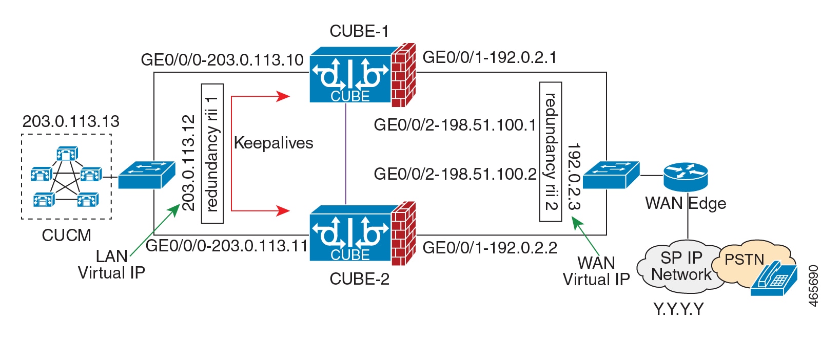
    Note


    However, it is recommended to use Portchannel for the RG control and data interfaces for redundancy. A single connection using back-to-back cable or switch presents a single point of failure due to a faulty cable, port, or switch, resulting in error state where both routers are Active.


  • If the RG ID is the same for the two different CUBE HA pairs, keepalive interface for check-pointing the RG control and data, and traffic must be in a different subnet or VLAN.


    Note


    This recommendation is applicable only if you connect using a switch, not by back-to-back cables.


  • You can configure a maximum of two redundancy groups. Hence, there can be only two Active and Standby pairs within the same network.


    Note


    This recommendation is applicable only if you connect using a switch, not by back-to-back cables.


  • Source all signaling and media from and to the Virtual IP address.

  • Always save the running configuration to avoid losing it due to router reload during a failover.

  • Virtual Routing and Forwarding

    • Define Virtual Router Forwarding (VRF) in the same order on both active and standby routers for an accurate synchronization of data.

    • You can configure VRFs only on Traffic interfaces (SIP and RTP). Do not configure VRF on RG Control and Data interface.

    • VRF configurations on both the active and standby router must be identical. VRF IDs are checkpointed for the calls before and after switchover (includes VRF-based RTP port range).

  • Manually copy the configurations from one router to the other.

  • Replicating the configuration on the Standby router does not commit to the startup configuration; it is in the running configuration. You must run the write memory command to commit the changes that are synchronized from the active router on the standby router.

Considerations and Restrictions

The following is a list of further considerations and restrictions you should know before configuring this topology:

Considerations

  • The same platform and configurations including interface must be used for the Active and Standby routers.

  • IPv6 flows in high availability is supported starting from Cisco IOS XE Dublin 17.12.1a release.

  • Only active calls are checkpointed (Calls that are connected with 200 OK or ACK transaction completed).

  • When you apply and save the configuration for the first time, the platform must be reloaded.

  • If you have Cisco Unified Customer Voice Portal (CVP) in your network, we recommend that you configure TCP session transport for the SIP trunk between CVP and CUBE.

  • Upon failover, the previously active CUBE reloads by design.

  • Smart Licensing communications happen through an active CUBE.

  • Transport layer sessions (TCP/TLS/UDP) are not check-pointed between high availability pair and check will not be preserved.

  • TCP sessions are not preserved during the failover. Remote user agents are expected to reestablish TCP sessions (using port 5060 or 5061) before sending subsequent messages.

  • Call Admission Control (CAC) state is maintained through switchover. After Stateful Switchover, no calls are allowed if the CAC limit is reached before the switchover.

  • Up to six multimedia lines in the SDP are checkpointed for CUBE high availability. From Cisco IOS XE Release 3.17 onwards, SDP Passthru (up to two m-lines) calls are also checkpointed.

  • Survivability.tcl preservation is supported from Cisco IOS XE Release 3.17 onwards for Unified Customer Voice Portal (CVP) deployments.

  • SRTP-RTP, SRTP-SRTP, and SRTP Passthru are supported.


    Note


    Redundancy control traffic that is exchanged between CUBE-1 and CUBE-2 is not secured natively and displays SRTP encryption keys in cleartext. If SRTP is used, you must secure this traffic by configuring a transport IPsec tunnel between the two interfaces used as the redundancy control link.


  • Port channel is supported for both RG control data and traffic interfaces only from Cisco IOS XE 16.3.1 onwards.

    Figure 5. Additional Supported Options for CUBE HA
  • LTI-based transcoder call flow preservation is supported from Cisco IOS XE Release 3.15 onwards and requires the same DSP module capacity on both active and standby in the same slot or subslot.

  • While deploying High Availability pair with Application Centric Infrastructure (ACI), perform one of the following:

    • Disable IP data plane learning on the ACI VRF.

    • Refer to IP Data-plane Learning for details.

    • Use an intermediate Layer 3 switch between the High Availability pair and the ACI deployment. This Layer 3 switch prevents the ACI from directly learning the CUBE IP address and its associated MAC addresses.

Restrictions

  • All SCCP-based media resources (Conference bridge, Transcoding, Hardware MTP, and Software MTP) are not supported.

  • Cisco Unified Survivable Remote Site Telephony (Unified SRST) or TDM Gateway co-location on CUBE HA is not supported.

  • Routers connected through Metropolitan Area Network (MAN) Ethernet regardless of latency are not supported.

  • Out-of-band DTMF (Notify or KPML) is not supported post switchover. Only rtp-nte to rtp-nte and voice-inband to voice-inband DTMF works after the switchover.

  • Media-flow around and UC Services API (Cisco Unified Communications Manager Network-Based Recording) are not supported.

  • You cannot terminate Wide Area Network (WAN) on CUBE directly or Data HA on either side. Both active and standby routers must be in the same Data Center and connected to the same physical switch.

  • The Courtesy Callback (CCB) feature is not supported if a callback was registered with Cisco Unified Customer Voice Portal (CVP) and then a switchover was done on CUBE.

  • You cannot configure a secondary IP address for the interfaces.

  • If the redundancy group ID is same for the two different CUBE HA pairs, then the keepalive interface that is used for checkpointing RG control and data traffic must be in a different subnet or VLAN.

  • Call Progress Analysis (CPA) calls (before transferred to the agent), SCCP-based media resources, Noise Reduction, Acoustic Shock Protection (ASP), and transrating calls are not supported.

  • Transport layer sessions tcp/tls/udp are not preserved or checkpointed to standby.

  • The failover time for a Box-to-box application is higher than the Inbox application.

  • One CUBE must have lower IPs across all the three interfaces on the same CUBE platform. For instance, CUBE-1 must have lower IP addresses in Gig0/0/0 interface compared with CUBE-2 Gig0/0/0 interface.

  • CUBE box-to-box high availability requires same priority and threshold to be configured on both CUBE-1 and CUBE-2.

Configure CUBE High Availability on Cisco 4000 Series ISR and Cisco Catalyst 8000 Series Edge Platforms

Prerequisites

Ensure that you have the required licenses for configuring high availability. For detailed information, see Cisco Unified Border Element Data Sheet.

  • Connect the active and the standby router through a layer 2 connection for the control path.

  • Configure the Network Time Protocol (NTP) or set the clock to be identical on both active and standby routers, to allow timestamps and call timers to match.


    Note


    If switching network is of ACI, its recommended to deploy a L3 switch between CUBE HA and ACI and connect CUBE HA the L3 switch.


  • The latency times must be minimal on all control and data links to prevent timeouts.

  • Physically redundant links, such as Gigabit EtherChannel, must be used for the control and data paths.

Configure High Availability

Please note that the IPv6 configuration for high availability is supported for Cisco IOS XE Dublin 17.12.1a and later releases. IPv6 doesn't support redundancy control and data links, but only IPv4 supports.

SUMMARY STEPS

  1. Configure the Redundancy Group (RG).
  2. Configure interface tracking.
  3. Configure the interfaces.
  4. Configure SIP UA.
  5. Configure SIP Binding.
  6. Configure the Punt Policing feature.
  7. Configure the RG group under voice service voip . This enables Box-to-box CUBE HA.
  8. Configure the Media Inactivity timer.
  9. Reload the router.
  10. Configure the peer router.
  11. Point the attached devices to the CUBE Virtual IP (VIP) address.

DETAILED STEPS


Step 1

Configure the Redundancy Group (RG).

  1. Enter application redundancy mode.

    Example:

    
    Router>enable
    Router#configure terminal 
    Router(config)#redundancy 
    Router(config-r)#mode none
    Router(config-red)#application redundancy
    Router(config-red-app)#group 1
    
  2. Configure a name for the redundancy group.

    Example:

    Router(config-red-app-grp)#name cube-ha

    where cube-ha is the name of the redundancy group.

  3. Specify the initial priority and failover threshold for a redundancy group.

    Example:

    Router(config-red-app-grp)#priority 100 failover threshold 75

    where 100 is the priority value and 75 is the threshold value. Both routers should have the same priority and threshold values.

  4. Configure the timers for delay and reload.

    Example:

    Router(config-red-app-grp)#timers delay 30 reload 60

    Delay timer which is the amount of time to delay the RG group initialization and role negotiation after the interface comes up.

    Default: 30 seconds. Range is 0-10000 seconds.

    Reload timer is the amount of time to delay RG group initialization and role-negotiation after a reload.

    Default: 60 seconds. Range is 0-10000 seconds.

  5. Configure the interface used to exchange keepalive and hello messages between the router pair.

    Example:

    Router(config-red-app-grp)#control GigabitEthernet0/0/2 protocol 1

    where GigabitEthernet0/0/2 is the interface and protocol 1 is the protocol instance that is attached to the interface.

  6. Configure the interface that is used for data traffic checkpoints.

    Example:

    Router(config-red-app-grp)#data GigabitEthernet0/0/2

    Note


    Only IPv4 supports control and data link.

  7. Configure RG group tracking.

    Example:

    
    Router(config-red-app-grp)#track 1 shutdown 
    Router(config-red-app-grp)#track 2 shutdown
    
  8. Specify the protocol instance that attaches to a control interface and enters redundancy application protocol configuration mode.

    Example:

    Router(config-red-app-grp)#protocol 1
  9. Configure the two timers for hellotime and holdtime.

    Example:

    Router(config-red-app-grp)#timers hellotime 3 holdtime 10

    hellotime—Interval between successive hello messages.

    Default is 3 seconds. Range is 250 milliseconds—254 seconds.

    holdtime—The interval between the receipt of a hello message and the presumption that the sending router has failed. This duration has to be greater than the hellotime.

    Default is 10 seconds. Range is 750 milliseconds—255 seconds.

    We recommend that you configure the holdtime timer configured to be at least three times the value of the hellotime timer.

Step 2

Configure interface tracking.

The track command is used in RG to track the voice traffic interface state so that the active router initiates switchover after the traffic interface is down.

Configure the following commands at the global level to track the status of the interface.

Example:


Router(config)#track 1 interface GigabitEthernet0/0/0 line-protocol 
Router(config)#track 2 interface GigabitEthernet0/0/1 line-protocol

Step 3

Configure the interfaces.

  1. Configure the redundancy interface identifier for the redundancy group.

    Required for generating a Virtual MAC (VMAC) address. You must use the same rii ID value on the interface of each router (active and standby) that has the same Virtual IP address.

    If there is more than one box-to-box HA pair on the same LAN, each pair MUST have unique rii IDs on their respective interfaces (to prevent collision). show redundancy application group all must indicate the correct local and peer information.

    Example:

    
    Router(config)#interface GigabitEthernet0/0/0 
    Router(config-if)#ip address 10.1.20.135 255.255.0.0 
    Router(config-if)#ipv6 address 2001:10:1:20::135/64
    Router(config-if)#negotiation auto 
    Router(config-if)#redundancy rii 1
    
  2. Associate the interface with the redundancy group created. Following are the examples for IPv4 and IPv6 configurations:

    Example:

    
    Router(config-if)# redundancy group 1 ip 10.1.40.250 exclusive
    Router(config-if)# redundancy group 1 ipv6 2001:10:1:40::250/64 exclusive
  3. Configure interface for RG control and data.

    Note


    Only IPv4 supports redundancy control and data link.

    Example:

    
    Router(config)#interface GigabitEthernet0/0/2 
    Router(config-if)#ip address 10.1.20.113 255.255.255.0
    Router(config-if)#ipv6 address 2001:10.1.20::113/64
    Router(config-if)#media-type rj45 
    Router(config-if)#negotiation auto
    

Step 4

Configure SIP UA.

Configure the protocol mode. Supported protocol modes are IPv4, IPv6, and dual-stack configurations. IPv6 traffic flow and dual-stack for IPv4 to IPv6 interworking requires protocol mode configurations.

Example:


sip-ua
 transport tcp tls v1.2
 protocol mode ipv6
!

Step 5

Configure SIP Binding.

Configure CUBE to bind SIP messages to the interface that is configured with a Virtual IP address (VIP) for the RG group employed. The following example illustrates IPv4 SIP binding configurations:

Example:


Router(config)#dial-peer voice 1 voip
Router(config-dial-peer)#session protocol sipv2
Router(config-dial-peer)#incoming called-number 2000
Router(config-dial-peer)#voice-class sip bind control source-interface GigabitEthernet0/0/0
Router(config-dial-peer)#voice-class sip bind media source-interface GigabitEthernet0/0/0
Router(config-dial-peer)#codec g711ulaw
Router(config-dial-peer)#!

Router(config)#dial-peer voice 2 voip
Router(config-dial-peer)#destination-pattern 2000
Router(config-dial-peer)#session protocol sipv2
Router(config-dial-peer)#session target ipv4:203.0.113.13
Router(config-dial-peer)#voice-class sip bind control source-interface GigabitEthernet0/0/1
Router(config-dial-peer)#voice-class sip bind media source-interface GigabitEthernet0/0/1
Router(config-dial-peer)#codec g711ulaw

Note


The following example illustrates IPv6 configuration for high availability that is supported starting from Cisco IOS XE Dublin 17.12.1a release:

Example:


Router(config)#dial-peer voice 1 voip
Router(config-dial-peer)#session protocol sipv2
Router(config-dial-peer)#incoming called-number 2000
Router(config-dial-peer)#voice-class sip bind control source-interface GigabitEthernet0/0/0 ipv6-address 2001:10:1:20::145/64
Router(config-dial-peer)#voice-class sip bind media source-interface GigabitEthernet0/0/0 ipv6-address 2001:10:1:20::145/64
Router(config-dial-peer)#codec g711ulaw
Router(config-dial-peer)#!

Router(config)#dial-peer voice 2 voip
Router(config-dial-peer)#destination-pattern 2000
Router(config-dial-peer)#session protocol sipv2
Router(config-dial-peer)#session target ipv6:[2001:10:1:40:250:56ff:fe89:b7a]:2001
Router(config-dial-peer)#voice-class sip bind control source-interface GigabitEthernet0/0/1 ipv6-address 2001:10:1:20::101/64
Router(config-dial-peer)#voice-class sip bind media source-interface GigabitEthernet0/0/1 ipv6-address 2001:10:1:20::101/64
Router(config-dial-peer)#codec g711ulaw

Step 6

Configure the Punt Policing feature.

SIP packets towards the virtual IP address and physical IP address match different punt-cause codes. The punt-rate of the virtual IP address with a punt-cause of 60, is lower than the punt-rate of the physical IP address.

To ensure that the behaviour of the SIP packets towards virtual and physical IP address remains the same, you must increase the punt-rate of the virtual IP address by using the platform punt-policer command in global configuration mode.

Note


For Cisco IOS XE Releases 16.6.7, 16.9.4, 16.11.1, 16.12.1, 17.1.1 and later releases, you do not need to increase the punt-rate.

Example:

Router(config)# platform punt-policer 60 40000

In the preceding example, the punt-rate of the virtual IP address (punt-cause 60) is increased from the default value of 2000 to 40000.

The following table provides details of the fields of the CLI.

Table 2. CLI Fields

Keyword

Description

platform punt-policer

Configures the Punt Policing feature.

60

punt-cause —Punt cause. Range is 1–107. Punt cause of the virtual interface is 60.

40000

punt-rate—Rate limit in packets per second. Range is 10–146484.

Note


The default punt rate value of the virtual IP address and the physical IP address varies with the router platform.

Note


The default and maximum setting are platform specific. Default value is optimal for most deployments. Change the rate only when suggested by Cisco Support.

Step 7

Configure the RG group under voice service voip . This enables Box-to-box CUBE HA.

Example:


Router#voice service voip
Router(conf-voi-serv)#redundancy-group 1

Step 8

Configure the Media Inactivity timer.

The Media Inactivity Timer enables the active and standby router pair to monitor and disconnect calls if no Real-Time Protocol (RTP) packets are received within a configurable time period.

For the SIP calls, the switched over calls are cleared with signaling (as signaling information is preserved for switched calls).

The Media Inactivity Timer releases TCP-based and H.323-based calls. This is used to guard against any hung sessions resulting from the failover when a normal call disconnect does not clear the call.

You must configure the same duration for the Media Inactivity Timer on both routers. The default value is 30 seconds for SIP calls. The sample configuration is as follows:

Example:


Router(config)#ip rtcp report interval 9000
Router(config)#gateway
Router(config-gateway)#media-inactivity-criteria all
Router(config-gateway)#timer receive-rtp 1200
Router(config-gateway)#timer receive-rtcp 5

SIP call legs are cleared once the RTCP timer expires.

Step 9

Reload the router.

Once all the preceding configurations are completed, you must save the configurations, and reload the router.

Example:

Router>enable
Router#relaod

Step 10

Configure the peer router.

Follow the preceding steps to configure the standby router. Make sure that you use the correct IP addresses.

Step 11

Point the attached devices to the CUBE Virtual IP (VIP) address.

The IP-PBX, Unified SIP Proxy, or service provider must route the calls to CUBE’s Virtual IP address.

HA configuration does not handle SIP messages to the CUBE’s physical IP addresses.

  1. Go to System menu, and choose Service Parameters . At the bottom of the Service Parameters, enable Advanced .

  2. Set the Allow TCP KeepAlives for SIP to False.

  3. After this setting is saved, restart the CallManager Services.


Configuration Examples

Example: Control Interface Protocol Configuration

Router#configure terminal
Router(config)#redundancy
Router(config-red)#mode none
Router(config-red)#application redundancy
Router(config-red-app)#protocol 4
Router(config-red-app-prot)#name rg1
Router(config-red-app-prot)#timers hellotime 3 holdtime 10
Router(config-red-app-prot)#authentication text password      
      

Example: Redundancy Group Protocol Configuration

Router#configure terminal
Router(config)#redundancy
Router(red)#application redundancy
Router(config-red-app)#protocol 1
Router(config-red-app-prtcl)#name RG1
Router(config-red-app-prtcl)#timers hellotime 1 holdtime 3
Router(config-red-app-prtcl)#end
Router#configure terminal
Router(config)#redundancy
Router(red)#application redundancy
Router(config-red-app)#protocol 2
Router(config-red-app-prtcl)#name RG1
Router(config-red-app-prtcl)#end

Example: Redundant Traffic Interface Configuration

Following is an example for IPv6 configuration for high availability that is supported starting from Cisco IOS XE Dublin 17.12.1a.

Router#configure terminal
Router(config)#interface GigabitEthernet 0/0/2
Router(config-if)#ip address 10.1.20.113 255.0.0.0
Router(config-if)#ipv6 address 2001:10.1.20::113/64
Router(config-if)#ip nat outside
Router(config-if)#ip virtual-reassembly
Router(config-if)#negotiation auto
Router(config-if)#redundancy rii 200
Router(config-if)#redundancy group 1 ip 10.1.20.153 exclusive decrement 10
Router(config-if)#redundancy group 1 ipv6 2001:10:1:20::153/64 exclusive

Verify Your Configuration

All configuration commands in this task are optional. You can use the show commands in any order.

SUMMARY STEPS

  1. show redundancy application group [group-id | all]
  2. show redundancy application transport {clients | group [group-id]}
  3. show redundancy application protocol {protocol-id | group [group-id]}
  4. show redundancy application faults group [group-id]
  5. show redundancy application if-mgr group [group-id]
  6. show redundancy application control-interface group [group-id]
  7. show redundancy application data-interface group [group-id]

DETAILED STEPS


Step 1

show redundancy application group [group-id | all]

Example:

Router#show redundancy application group
Group ID    Group Name                      State
--------    ----------                      -----
1           Generic-Redundancy-1            STANDBY
2           Generic-Redundancy2             ACTIVE 

The following example shows the details of redundancy application group 1:

Router#show redundancy application group 1
Group ID:1
Group Name:Generic-Redundancy-1

Administrative State: No Shutdown
Aggregate operational state : Up
My Role: STANDBY
Peer Role: ACTIVE
Peer Presence: Yes
Peer Comm: Yes
Peer Progression Started: Yes

RF Domain: btob-one
RF state: STANDBY HOT
Peer RF state: ACTIVE

The following example shows the details of redundancy application group 2:

Router#show redundancy application group 2
Group ID:2
Group Name:Generic-Redundancy2

Administrative State: No Shutdown
Aggregate operational state : Up
My Role: ACTIVE
Peer Role: STANDBY
Peer Presence: Yes
Peer Comm: Yes
Peer Progression Started: Yes

RF Domain: btob-two
RF state: ACTIVE
Peer RF state: STANDBY HOT

Step 2

show redundancy application transport {clients | group [group-id]}

Example:

Router#show redundancy application transport client

Client         Conn#  Priority   Interface   L3        L4        
( 0)RF           0      1         CTRL       IPV4      SCTP      

( 1)MCP_HA       1      1         DATA       IPV4      UDP_REL   

( 4)AR           0      1         ASYM       IPV4      UDP       

( 5)CF           0      1         DATA       IPV4      SCTP  

The following example shows configuration details for the redundancy application transport group:

Router#show redundancy application transport group

Transport Information for RG (1) 
Client = RF  
TI   conn_id my_ip           my_port  peer_ip         peer_por intf    L3      L4      
0    0       1.1.1.1         59000    1.1.1.2         59000    CTRL    IPV4    SCTP    
Client = MCP_HA  
TI   conn_id my_ip           my_port  peer_ip         peer_por intf    L3      L4      
1    1       9.9.9.2         53000    9.9.9.1         53000    DATA    IPV4    UDP_REL 
Client = AR  
TI   conn_id my_ip           my_port  peer_ip         peer_por intf    L3      L4      
2    0       0.0.0.0         0        0.0.0.0         0        NONE_IN NONE_L3 NONE_L4 
Client = CF  
TI   conn_id my_ip           my_port  peer_ip         peer_por intf    L3      L4      
3    0       9.9.9.2         59001    9.9.9.1         59001    DATA    IPV4    SCTP    
Transport Information for RG (2) 
Client = RF  
TI   conn_id my_ip           my_port  peer_ip         peer_por intf    L3      L4      
8    0       1.1.1.1         59004    1.1.1.2         59004    CTRL    IPV4    SCTP    
Client = MCP_HA  
TI   conn_id my_ip           my_port  peer_ip         peer_por intf    L3      L4      
9    1       9.9.9.2         53002    9.9.9.1         53002    DATA    IPV4    UDP_REL 
Client = AR  
TI   conn_id my_ip           my_port  peer_ip         peer_por intf    L3      L4      
10   0       0.0.0.0         0        0.0.0.0         0        NONE_IN NONE_L3 NONE_L4 
Client = CF  
TI   conn_id my_ip           my_port  peer_ip         peer_por intf    L3      L4      
11   0       9.9.9.2         59005    9.9.9.1         59005    DATA    IPV4    SCTP

The following example shows the configuration details of redundancy application transport group 1:

Router#show redundancy application transport group 1

Transport Information for RG (1) 
Client = RF  
TI   conn_id my_ip           my_port  peer_ip         peer_por intf    L3      L4      
0    0       1.1.1.1         59000    1.1.1.2         59000    CTRL    IPV4    SCTP    
Client = MCP_HA  
TI   conn_id my_ip           my_port  peer_ip         peer_por intf    L3      L4      
1    1       9.9.9.2         53000    9.9.9.1         53000    DATA    IPV4    UDP_REL 
Client = AR  
TI   conn_id my_ip           my_port  peer_ip         peer_por intf    L3      L4      
2    0       0.0.0.0         0        0.0.0.0         0        NONE_IN NONE_L3 NONE_L4 
Client = CF  
TI   conn_id my_ip           my_port  peer_ip         peer_por intf    L3      L4      
3    0       9.9.9.2         59001    9.9.9.1         59001    DATA    IPV4    SCTP 

The following example shows configuration details of redundancy application transport group 2:

Router#show redundancy application transport group 2
Transport Information for RG (2) 
Client = RF  
TI   conn_id my_ip           my_port  peer_ip         peer_por intf    L3      L4      
8    0       1.1.1.1         59004    1.1.1.2         59004    CTRL    IPV4    SCTP    
Client = MCP_HA  
TI   conn_id my_ip           my_port  peer_ip         peer_por intf    L3      L4      
9    1       9.9.9.2         53002    9.9.9.1         53002    DATA    IPV4    UDP_REL 
Client = AR  
TI   conn_id my_ip           my_port  peer_ip         peer_por intf    L3      L4      
10   0       0.0.0.0         0        0.0.0.0         0        NONE_IN NONE_L3 NONE_L4 
Client = CF  
TI   conn_id my_ip           my_port  peer_ip         peer_por intf    L3      L4      
11   0       9.9.9.2         59005    9.9.9.1         59005    DATA    IPV4    SCTP 

Step 3

show redundancy application protocol {protocol-id | group [group-id]}

Example:

Router#show redundancy application protocol group

RG Protocol RG 1
------------------
Role: Standby
Negotiation: Enabled
Priority: 50
Protocol state: Standby-hot
Ctrl Intf(s) state: Up
Active Peer: address 1.1.1.2, priority 150, intf Gi0/0/0
Standby Peer: Local
Log counters:
role change to active: 0
role change to standby: 1
disable events: rg down state 1, rg shut 0
ctrl intf events: up 2, down 1, admin_down 1
reload events: local request 0, peer request 0
 
RG Media Context for RG 1
--------------------------
Ctx State: Standby
Protocol ID: 1
Media type: Default
Control Interface: GigabitEthernet0/0/0
Current Hello timer: 3000
Configured Hello timer: 3000, Hold timer: 10000
Peer Hello timer: 3000, Peer Hold timer: 10000
Stats:
Pkts 117, Bytes 7254, HA Seq 0, Seq Number 117, Pkt Loss 0
Authentication not configured
Authentication Failure: 0
Reload Peer: TX 0, RX 0
Resign: TX 0, RX 0
Active Peer: Present. Hold Timer: 10000
Pkts 115, Bytes 3910, HA Seq 0, Seq Number 1453975, Pkt Loss 0


RG Protocol RG 2
------------------
Role: Active
Negotiation: Enabled
Priority: 135
Protocol state: Active
Ctrl Intf(s) state: Up
Active Peer: Local
Standby Peer: address 1.1.1.2, priority 130, intf Gi0/0/0
Log counters:
role change to active: 1
role change to standby: 1
disable events: rg down state 1, rg shut 0
ctrl intf events: up 2, down 1, admin_down 1
reload events: local request 0, peer request 0
 
RG Media Context for RG 2
--------------------------
Ctx State: Active
Protocol ID: 2
Media type: Default
Control Interface: GigabitEthernet0/0/0
Current Hello timer: 3000
Configured Hello timer: 3000, Hold timer: 10000
Peer Hello timer: 3000, Peer Hold timer: 10000
Stats:
Pkts 118, Bytes 7316, HA Seq 0, Seq Number 118, Pkt Loss 0
Authentication not configured
Authentication Failure: 0
Reload Peer: TX 0, RX 0
Resign: TX 0, RX 1
Standby Peer: Present. Hold Timer: 10000
Pkts 102, Bytes 3468, HA Seq 0, Seq Number 1453977, Pkt Loss 0

The following example shows configuration details for the redundancy application protocol group 1:

Router#show redundancy application protocol group 1

RG Protocol RG 1
------------------
Role: Standby
Negotiation: Enabled
Priority: 50
Protocol state: Standby-hot
Ctrl Intf(s) state: Up
Active Peer: address 1.1.1.2, priority 150, intf Gi0/0/0
Standby Peer: Local
Log counters:
role change to active: 0
role change to standby: 1
disable events: rg down state 1, rg shut 0
ctrl intf events: up 2, down 1, admin_down 1
reload events: local request 0, peer request 0
 
RG Media Context for RG 1
--------------------------
Ctx State: Standby
Protocol ID: 1
Media type: Default
Control Interface: GigabitEthernet0/0/0
Current Hello timer: 3000
Configured Hello timer: 3000, Hold timer: 10000
Peer Hello timer: 3000, Peer Hold timer: 10000
Stats:
Pkts 120, Bytes 7440, HA Seq 0, Seq Number 120, Pkt Loss 0
Authentication not configured
Authentication Failure: 0
Reload Peer: TX 0, RX 0
Resign: TX 0, RX 0
Active Peer: Present. Hold Timer: 10000
Pkts 118, Bytes 4012, HA Seq 0, Seq Number 1453978, Pkt Loss 0

The following example shows configuration details for the redundancy application protocol group 2:

Router# show redundancy application protocol group 2

RG Protocol RG 2
------------------
Role: Active
Negotiation: Enabled
Priority: 135
Protocol state: Active
Ctrl Intf(s) state: Up
Active Peer: Local
Standby Peer: address 1.1.1.2, priority 130, intf Gi0/0/0
Log counters:
role change to active: 1
role change to standby: 1
disable events: rg down state 1, rg shut 0
ctrl intf events: up 2, down 1, admin_down 1
reload events: local request 0, peer request 0
 
RG Media Context for RG 2
--------------------------
Ctx State: Active
Protocol ID: 2
Media type: Default
Control Interface: GigabitEthernet0/0/0
Current Hello timer: 3000
Configured Hello timer: 3000, Hold timer: 10000
Peer Hello timer: 3000, Peer Hold timer: 10000
Stats:
Pkts 123, Bytes 7626, HA Seq 0, Seq Number 123, Pkt Loss 0
Authentication not configured
Authentication Failure: 0
Reload Peer: TX 0, RX 0
Resign: TX 0, RX 1
Standby Peer: Present. Hold Timer: 10000
Pkts 107, Bytes 3638, HA Seq 0, Seq Number 1453982, Pkt Loss 0

The following example shows configuration details for the redundancy application protocol 1:

Router#show redundancy application protocol 1

Protocol id: 1, name: rg-protocol-1
Hello timer in msecs: 3000
Hold timer in msecs: 10000
OVLD-1#show redundancy application protocol 2
Protocol id: 2, name: rg-protocol-2
Hello timer in msecs: 3000
Hold timer in msecs: 10000

Step 4

show redundancy application faults group [group-id]

Example:

Router#show redundancy application faults group

Faults states Group 1 info:
Runtime priority: [50]
RG Faults RG State: Up.
Total # of switchovers due to faults: 0
Total # of down/up state changes due to faults: 2
Faults states Group 2 info:
Runtime priority: [135]
RG Faults RG State: Up.
Total # of switchovers due to faults: 0
Total # of down/up state changes due to faults: 2

The following example shows configuration details specific to redundancy application faults group 1:

Router#show redundancy application faults group 1

Faults states Group 1 info:
Runtime priority: [50]
RG Faults RG State: Up.
Total # of switchovers due to faults: 0
Total # of down/up state changes due to faults: 2

The following example shows configuration details specific to redundancy application faults group 2:

Router#show redundancy application faults group 2
Faults states Group 2 info:
Runtime priority: [135]
RG Faults RG State: Up.
Total # of switchovers due to faults: 0
Total # of down/up state changes due to faults: 2

Step 5

show redundancy application if-mgr group [group-id]

Example:

Router#show redundancy application if-mgr group 
 
RG ID: 1
 ==========

 interface      GigabitEthernet0/0/3.152
 ---------------------------------------
 VMAC           0007.b421.4e21
 VIP            55.1.1.255
 Shut           shut
 Decrement      10

 interface      GigabitEthernet0/0/2.152
 ---------------------------------------
 VMAC           0007.b421.5209
 VIP            45.1.1.255
 Shut           shut
 Decrement      10


 RG ID: 2
 ==========

 interface      GigabitEthernet0/0/3.166
 ---------------------------------------
 VMAC           0007.b422.14d6
 VIP            4.1.255.254
 Shut           no shut
 Decrement      10

 interface      GigabitEthernet0/0/2.166
 ---------------------------------------
 VMAC           0007.b422.0d06
 VIP            3.1.255.254
 Shut           no shut
 Decrement      10

The following examples shows configuration details for redundancy application interface manager group 1 and group 2:

Router#show redundancy application if-mgr group 1
 
 RG ID: 1
 ==========

 interface      GigabitEthernet0/0/3.152
 ---------------------------------------
 VMAC           0007.b421.4e21
 VIP            55.1.1.255
 Shut           shut
 Decrement      10

 interface      GigabitEthernet0/0/2.152
 ---------------------------------------
 VMAC           0007.b421.5209
 VIP            45.1.1.255
 Shut           shut
 Decrement      10

Router#show redundancy application if-mgr group 2

 RG ID: 2
 ==========

 interface      GigabitEthernet0/0/3.166
 ---------------------------------------
 VMAC           0007.b422.14d6
 VIP            4.1.255.254
 Shut           no shut
 Decrement      10

 interface      GigabitEthernet0/0/2.166
 ---------------------------------------
 VMAC           0007.b422.0d06
 VIP            3.1.255.254
 Shut           no shut
 Decrement      10

Step 6

show redundancy application control-interface group [group-id]

Example:

Router#show redundancy application control-interface group

The control interface for rg[1] is GigabitEthernet0/0/0
Interface is Control interface associated with the following protocols: 2 1 
Interface Neighbors:
Peer: 1.1.1.2 Active RGs: 1 Standby RGs: 2

The control interface for rg[2] is GigabitEthernet0/0/0
Interface is Control interface associated with the following protocols: 2 1 
Interface Neighbors:
Peer: 1.1.1.2 Active RGs: 1 Standby RGs: 2 

The following example shows configuration details of the redundancy application control-interface group 1:

Router#show redundancy application control-interface group 1

The control interface for rg[1] is GigabitEthernet0/0/0
Interface is Control interface associated with the following protocols: 2 1
Interface Neighbors:
Peer: 1.1.1.2 Active RGs: 1 Standby RGs: 2

The following example shows configuration details of the redundancy application control-interface group 2:

Router#show redundancy application control-interface group 2

The control interface for rg[2] is GigabitEthernet0/0/0
Interface is Control interface associated with the following protocols: 2 1
Interface Neighbors:
Peer: 1.1.1.2 Active RGs: 1 Standby RGs: 2 

Step 7

show redundancy application data-interface group [group-id]

Example:

Router#show redundancy application data-interface group

The data interface for rg[1] is GigabitEthernet0/0/1
The data interface for rg[2] is GigabitEthernet0/0/1

The following examples show configuration details specific to redundancy application data-interface group 1 and group 2:

Router#show redundancy application data-interface group 1
The data interface for rg[1] is GigabitEthernet0/0/1
 
Router#show redundancy application data-interface group 2
The data interface for rg[2] is GigabitEthernet0/0/1


Tips to Troubleshoot

Use the following show and debug commands to troubleshoot any issues:

  • show redundancy application group all

  • show redundancy application transport clients

  • show redundancy client domain all | inc VOIP RG

  • show voice high-availability summary

  • show voip fpi stats

  • debug voip rtp session

  • debug voice high-availability all

  • debug voip fpi all

  • debug redundancey application group {config | faults | media | protocol | rii transport | vp}


Note


Do not turn on a large number of debugs on a system carrying high volume of active call traffic.