High Availability on Cisco ASR 1000 and Cisco Catalyst 8000 Series Routers

Feature Information

Table 1. Feature Information

Feature Name

Releases

Feature Information

High Availability Support on Cisco Unified Border Element (CUBE)

Baseline Functionality

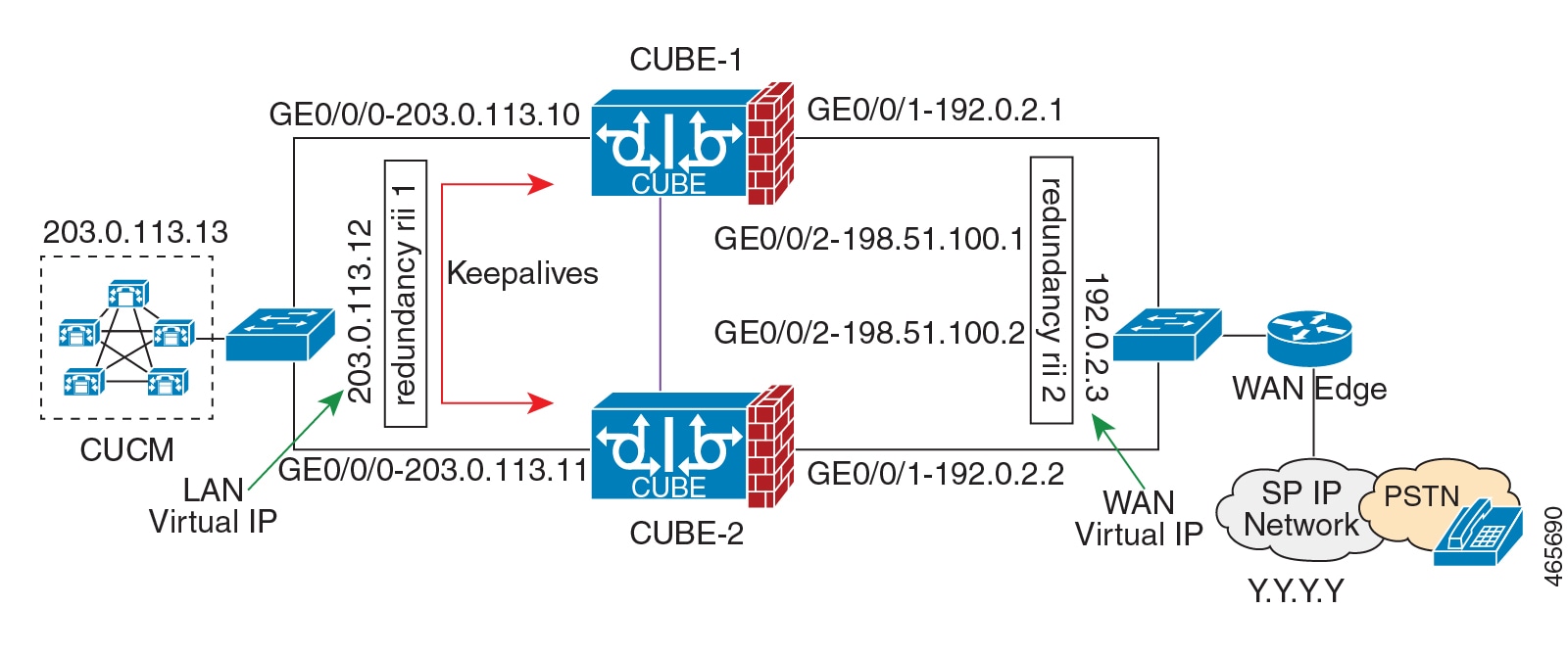
CUBE supports redundancy and failover capability on active and standby routers.

IPv6 flows in High Availability

Cisco IOS XE Dublin 17.12.1a

The support for IPv6 flows in high availability is introduced.

Overview


Note


H.323 protocol is no longer supported from Cisco IOS XE Bengaluru 17.6.1a onwards. Consider using SIP for multimedia applications.


The High Availability (HA) feature allows you to benefit from the failover capability of Cisco Unified Border Element (CUBE) on two routers, one active and one standby. When the active router goes down for any reason, the standby router takes over seamlessly, preserving and processing your calls.

Figure 1. CUBE High Availability


CUBE supports two HA options on the Cisco ASR 1000 Series Aggregation Services Router:

  • Box-to-box Redundancy

  • Inbox Redundancy

The following table describes the Cisco ASR 1000 Series Router models supported for each redundancy type:

Table 2. Redundancy Type, Supported Models, and Supported Cisco IOS XE Release

Redundancy Type

Router Models

Supported Cisco IOS-XE Release

Box-to-box

  • Cisco ASR 1001-X Router

  • Cisco ASR 1002-X Router

  • Cisco ASR 1004 Router

  • Cisco ASR 1006 Router (with a single RP and an ESP)

  • Cisco ASR 1006-X Router (with a single RP and an ESP)

Cisco IOS XE Release 3.11 onwards

Inbox

Cisco ASR 1006 Router

Cisco IOS XE Release 3.11 onwards


Note


Cisco ASR 1006 supports both Box-to-box and Inbox redundancy. You cannot switch between these two modes dynamically.


The following table provides details on the type of information that is preserved in different call types:

Table 3. Call Preservation for Various Call Types

Call Type

Transport Layer

Call Preservation After Switchover

SIP-SIP

UDP

Both media and session signaling are preserved.

SIP-SIP

TCP/TLS

Both media and session signaling are preserved using port 5060.

Inbox Redundancy

Inbox redundancy with Stateful Switchover (SSO) mechanism provides redundancy within the same device. Cisco ASR1006 supports the stateful failover from an active Enhanced Services Processor (ESP) to a standby and from an active Route Processor to a standby on the same box.

Figure 2. Inbox Redundancy


Box-to-Box Redundancy

Box-to-box redundancy enables configuring a pair of routers to act as back up for each other. In the router pair, the active router is determined based on the failover conditions. The router pair continuously exchange status messages. CUBE session information is checkpointed across the active and standby router. This enables the standby router to immediately take over all CUBE call processing responsibilities when the active router becomes unavailable.

Redundancy Group (RG) Infrastructure

A group of redundant interfaces form a Redundancy Group. The active and standby routers are connected by a configurable control link and data synchronization link. The control link is used to communicate the redundancy state for each router. The data synchronization link is used to transfer stateful information to synchronize the stateful database for the calls and media flows. Each pair of redundant interfaces is configured with the same unique ID number, also known as the Redundancy Interface Identifier (RII).

A Virtual IP address (VIP) is configured on interfaces that connect to the external network. All signaling and media is sourced from and sent to the Virtual IP address. External devices such as Cisco Unified Communication Manager, uses VIP as the destination IP address for the calls traversing through CUBE.

The following figure shows the redundancy group configured for a pair of routers with a single outgoing interface.

Figure 3. Redundancy Group Configuration

PROTECTED Mode

The default failover redundancy behavior in a box-to-box HA pair is to reload the affected router to avoid out-of-sync conditions or Split brain. From release IOS XE 3.11 onwards, you can configure a Cisco ASR 1000 Series Router to transition into PROTECTED mode, which has the following features:

  • Bulk sync request, Call checkpointing, and incoming call processing are disabled.

  • You must manually reload a router in PROTECTED mode to come out of this state.

To enable the PROTECTED mode, use the no redundancy-reload command under voice service voip .

Network Topology

This section describes how to configure the following network topology, in which an active and standby pair of routers is used in a SIP trunk deployment between a Cisco Unified Communications Manager (Unified CM) and a service provider (SP) SIP trunk for PSTN access.

In this topology, both active and standby routers have the same configuration and both platforms are connected through a physical switch across same interfaces. This is required for CUBE HA to work. For example, the CUBE-1 and CUBE-2 interface towards WAN must terminate on the same switch. Multiple interfaces or sub-interfaces can be used on either LAN or WAN side. Also, one CUBE has a lower IP address across all three interfaces on the same CUBE paltform.

We recommend that you keep the following in mind when configuring this topology:

  • Connect the redundancy group control and data interfaces in the CUBE HA pair to the same physical switch to avoid any latency in the network.

  • The RG control and data interfaces of the CUBE HA pair can be connected through a back-to-back cable or using a switch as shown in the following figures:

    Figure 4. Network Topology with switch between active and standby routers
    Figure 5. Network Topology with crossover cable between active and standby routers

    Note


    However, it is recommended to use Portchannel for the RG control and data interfaces for redundancy. A single connection using back-to-back cable or switch presents a single point of failure due to a faulty cable, port, or switch, resulting in error state where both routers are Active.


  • If the RG ID is the same for the two different CUBE HA pairs, keepalive interface for check-pointing the RG control and data, and traffic must be in a different subnet or VLAN.


    Note


    This recommendation is applicable only if you connect using a switch, not by back-to-back cables.


  • You can configure a maximum of two redundancy groups. Hence, there can be only two Active and Standby pairs within the same network.


    Note


    This recommendation is applicable only if you connect using a switch, not by back-to-back cables.


  • Source all signaling and media from and to the Virtual IP address.

  • Always save the running configuration to avoid losing it due to router reload during a failover.

  • Virtual Routing and Forwarding

    • Define Virtual Router Forwarding (VRF) in the same order on both active and standby routers for an accurate synchronization of data.

    • You can configure VRFs only on Traffic interfaces (SIP and RTP). Do not configure VRF on RG Control and Data interface.

    • VRF configurations on both the active and standby router must be identical. VRF IDs are checkpointed for the calls before and after switchover (includes VRF-based RTP port range).

  • Manually copy the configurations from one router to the other.

  • Replicating the configuration on the Standby router does not commit to the startup configuration; it is in the running configuration. You must run the write memory command to commit the changes that are synchronized from the active router on the standby router.

Considerations and Restrictions

The following is a list of further considerations and restrictions you should know before configuring this topology:

Considerations

  • The same platform and configurations including interface must be used for the Active and Standby routers.

  • IPv6 flows in high availability is supported starting from Cisco IOS XE Dublin 17.12.1a release.

  • Only active calls are checkpointed (Calls that are connected with 200 OK or ACK transaction completed).

  • When you apply and save the configuration for the first time, the platform must be reloaded.

  • If you have Cisco Unified Customer Voice Portal (CVP) in your network, we recommend that you configure TCP session transport for the SIP trunk between CVP and CUBE.

  • Upon failover, the previously active CUBE reloads by design.

  • Smart Licensing communications happen through an active CUBE.

  • Transport layer sessions (TCP/TLS/UDP) are not check-pointed between high availability pair and check will not be preserved.

  • TCP sessions are not preserved during the failover. Remote user agents are expected to reestablish TCP sessions (using port 5060 or 5061) before sending subsequent messages.

  • Call Admission Control (CAC) state is maintained through switchover. After Stateful Switchover, no calls are allowed if the CAC limit is reached before the switchover.

  • Up to six multimedia lines in the SDP are checkpointed for CUBE high availability. From Cisco IOS XE Release 3.17 onwards, SDP Passthru (up to two m-lines) calls are also checkpointed.

  • Survivability.tcl preservation is supported from Cisco IOS XE Release 3.17 onwards for Unified Customer Voice Portal (CVP) deployments.

  • SRTP-RTP, SRTP-SRTP, and SRTP Passthru are supported.


    Note


    Redundancy control traffic that is exchanged between CUBE-1 and CUBE-2 is not secured natively and displays SRTP encryption keys in cleartext. If SRTP is used, you must secure this traffic by configuring a transport IPsec tunnel between the two interfaces used as the redundancy control link.


  • Port channel is supported for both RG control data and traffic interfaces only from Cisco IOS XE 16.3.1 onwards.

    Figure 6. Additional Supported Options for CUBE HA
  • LTI-based transcoder call flow preservation is supported from Cisco IOS XE Release 3.15 onwards and requires the same DSP module capacity on both active and standby in the same slot or subslot.

  • While deploying High Availability pair with Application Centric Infrastructure (ACI), perform one of the following:

    • Disable IP data plane learning on the ACI VRF.

    • Refer to IP Data-plane Learning for details.

    • Use an intermediate Layer 3 switch between the High Availability pair and the ACI deployment. This Layer 3 switch prevents the ACI from directly learning the CUBE IP address and its associated MAC addresses.

  • From release Cisco IOS-XE 3.11 onwards, upon failover, you can move the previously active CUBE to a PROTECTED state to avoid the reload.

Restrictions

  • All SCCP-based media resources (Conference bridge, Transcoding, Hardware MTP, and Software MTP) are not supported.

  • Cisco Unified Survivable Remote Site Telephony (Unified SRST) or TDM Gateway co-location on CUBE HA is not supported.

  • Routers connected through Metropolitan Area Network (MAN) Ethernet regardless of latency are not supported.

  • Out-of-band DTMF (Notify or KPML) is not supported post switchover. Only rtp-nte to rtp-nte and voice-inband to voice-inband DTMF works after the switchover.

  • Media-flow around and UC Services API (Cisco Unified Communications Manager Network-Based Recording) are not supported.

  • You cannot terminate Wide Area Network (WAN) on CUBE directly or Data HA on either side. Both active and standby routers must be in the same Data Center and connected to the same physical switch.

  • The Courtesy Callback (CCB) feature is not supported if a callback was registered with Cisco Unified Customer Voice Portal (CVP) and then a switchover was done on CUBE.

  • You cannot configure a secondary IP address for the interfaces.

  • If the redundancy group ID is same for the two different CUBE HA pairs, then the keepalive interface that is used for checkpointing RG control and data traffic must be in a different subnet or VLAN.

  • One CUBE must have lower IPs across all the three interfaces on the same CUBE platform. For instance, CUBE-1 must have lower IP addresses in Gig0/0/0 interface compared with CUBE-2 Gig0/0/0 interface.

  • CUBE box-to-box high availability requires same priority and threshold to be configured on both CUBE-1 and CUBE-2.

Configure CUBE High Availability on Cisco ASR 1000 and Cisco Catalyst 8000 Series Routers

Before You Begin

  • Use the same hardware platform, including the cards and their positioning.

  • Place both active and standby routers physically in the same location, which is connected to the same Ethernet LAN.

  • If there are currently dual RPs or ESPs in the Cisco ASR 1006 Router, remove the extra RP or ESP and reload the router before configuring the redundancy mode.

Ensure that you have the required licenses for configuring high availability. For detailed information, see Cisco Unified Border Element Data Sheet.

In addition to an ASR1000 platform license (Advanced IP or Advanced Enterprise) and CUBE session licenses, a Firewall/NAT Stateful Inter-Chassis Redundancy License (Part number: FLSASR1-FWNAT-R) is also required for Box-to-Box High Availability configurations.

Configure Inbox High Availability

Procedure


Enable inbox redundancy.

Example:


Router>enable
Router#configure terminal 
Router(config)#redundancy 
Router(config-r)#mode sso
Router(config-r)#interchassis group 1
Router(config-r)#main-cpu
Router(config-r)#stanby console enable
Router(config-r)#end
Router(config)#copy run start /* This is to save the configuration */


Configure Box-to-Box High Availability

IPv6 configuration for high availability is supported for Cisco IOS XE Dublin 17.12.1a and later releases. IPv6 doesn't support control and data links, but IPv4 supports.

SUMMARY STEPS

  1. Disable inbox and software redundancy.
  2. Configure the Redundancy Group (RG).
  3. Configure interface tracking.
  4. Configure the interfaces.
  5. Configure SIP UA.
  6. Configure SIP Binding.
  7. (Optional) If H.323 calls are involved, enable H.323 binding.
  8. Configure the Punt Policing feature.
  9. Configure the RG group under voice service voip . This enables Box-to-box CUBE HA.
  10. Configure the Media Inactivity timer.
  11. Reload the router.
  12. Configure the peer router.
  13. Point the attached devices to the CUBE Virtual IP (VIP) address.

DETAILED STEPS


Step 1

Disable inbox and software redundancy.

  1. Disable software redundancy.

    Example:

    Disable software redundancy:

    
    Router>enable
    Router#configure terminal 
    Router(config)#redundancy 
    Router(config-r)#mode none
    

    Example:

    Disable the inbox redundancy if you are using ASR1006 router:

    
    Router>enable
    Router#configure terminal 
    Router(config)#redundancy 
    Router(config-r)#mode rpr
    
  2. Save the running configuration to a text file in the bootflash.

    Example:

    
    Router>enable
    Router#copy running-configuration bootflash:<filename>
    

    In the preceding command, provide a name of your preference for <filename>.

  3. Force the router to go into ROMMON mode upon next reload and erase the existing configuration from the NVRAM:

    Example:

    
    Router>enable
    Router#configure terminal 
    Router(config)#config-register 0x0 
    Router(config)#write erase
    
  4. Reload the router.

    Example:

    
    Router>enable
    Router#reload
    
  5. At ROMMON prompt, reset the IOSXE_Dual_IOS variable to disable the software redundancy.

    Example:

    
    rommon1>IOSXE_DUAL_IOS=0 
    rommon2>sync
    
  6. Boot the image from the bootflash or harddisk, or from the network.

    Example:

    rommon1>boot bootflash:isr4400-universalk9.03.13.02.S.154-3.S2-ext.SPA.bin
  7. When the router is up, re-apply the old configuration by copying the configuration file to the running-configuration.

    Example:

    
    Router>enable
    Router#copy bootflash:sampleconfig running-configuration
    
  8. Change the config register back to a non-zero value.

    Example:

    
    Router>enable
    Router#Config-register 0x2102
    

Step 2

Configure the Redundancy Group (RG).

  1. Enter application redundancy mode.

    Example:

    
    Router>enable
    Router#configure terminal 
    Router(config)#redundancy 
    Router(config-r)#mode none
    Router(config-red)#application redundancy
    Router(config-red-app)#group 1
    
  2. Configure a name for the redundancy group.

    Example:

    Router(config-red-app-grp)#name cube-ha

    where cube-ha is the name of the redundancy group.

  3. Specify the initial priority and failover threshold for a redundancy group.

    Example:

    Router(config-red-app-grp)#priority 100 failover threshold 75

    where 100 is the priority value and 75 is the threshold value. Both routers should have the same priority and threshold values.

  4. Configure the timers for delay and reload.

    Example:

    Router(config-red-app-grp)#timers delay 30 reload 60

    Delay timer which is the amount of time to delay the RG group initialization and role negotiation after the interface comes up.

    Default: 30 seconds. Range is 0-10000 seconds.

    Reload timer is the amount of time to delay RG group initialization and role-negotiation after a reload.

    Default: 60 seconds. Range is 0-10000 seconds.

  5. Configure the interface used to exchange keepalive and hello messages between the router pair.

    Example:

    Router(config-red-app-grp)#control GigabitEthernet0/0/2 protocol 1

    where GigabitEthernet0/0/2 is the interface and protocol 1 is the protocol instance that is attached to the interface.

  6. Configure the interface that is used for data traffic checkpoints.

    Example:

    Router(config-red-app-grp)#data GigabitEthernet0/0/2

    Note


    Only IPv4 supports control and data link.

  7. Configure RG group tracking.

    Example:

    
    Router(config-red-app-grp)#track 1 shutdown 
    Router(config-red-app-grp)#track 2 shutdown
    

    If you want protected mode, enter the following command:

    
    Router(config-red-app-grp)#track 3 shutdown
  8. Specify the protocol instance that attaches to a control interface and enters redundancy application protocol configuration mode.

    Example:

    Router(config-red-app-grp)#protocol 1
  9. Configure the two timers for hellotime and holdtime.

    Example:

    Router(config-red-app-grp)#timers hellotime 3 holdtime 10

    hellotime—Interval between successive hello messages.

    Default is 3 seconds. Range is 250 milliseconds—254 seconds.

    holdtime—The interval between the receipt of a hello message and the presumption that the sending router has failed. This duration has to be greater than the hellotime.

    Default is 10 seconds. Range is 750 milliseconds—255 seconds.

    We recommend that you configure the holdtime timer configured to be at least three times the value of the hellotime timer.

Step 3

Configure interface tracking.

The track command is used in RG to track the voice traffic interface state so that the active router initiates switchover after the traffic interface is down.

Configure the following commands at the global level to track the status of the interface.


Router(config)#track 1 interface GigabitEthernet0/0/0 line-protocol 
Router(config)#track 2 interface GigabitEthernet0/0/1 line-protocol

If you want protected mode, enter the following command:

Router(config)#track 3 interface GigabitEthernet0/0/2 line-protocol

Step 4

Configure the interfaces.

  1. Configure the redundancy interface identifier for the redundancy group.

    Required for generating a Virtual MAC (VMAC) address. You must use the same rii ID value on the interface of each router (active and standby) that has the same Virtual IP address.

    If there is more than one box-to-box HA pair on the same LAN, each pair MUST have unique rii IDs on their respective interfaces (to prevent collision). show redundancy application group all must indicate the correct local and peer information.

    Example:

    
    Router(config)#interface GigabitEthernet0/0/0 
    Router(config-if)#ip address 10.1.20.135 255.255.0.0 
    Router(config-if)#ipv6 address 2001:10:1:20::135/64
    Router(config-if)#negotiation auto 
    Router(config-if)#redundancy rii 1
    
  2. Associate the interface with the redundancy group created. Following are the examples for IPv4 and IPv6 configurations:

    Example:

    
    Router(config-if)# redundancy group 1 ip 10.1.40.250 exclusive
    Router(config-if)# redundancy group 1 ipv6 2001:10:1:40::250/64 exclusive
  3. Configure interface for RG control and data.

    Note


    Only IPv4 supports redundancy control and data link.

    Example:

    
    Router(config)#interface GigabitEthernet0/0/2 
    Router(config-if)#ip address 10.1.20.113 255.255.255.0
    Router(config-if)#ipv6 address 2001:10.1.20::113/64
    Router(config-if)#media-type rj45 
    Router(config-if)#negotiation auto
    

Step 5

Configure SIP UA.

Configure the protocol mode. Supported protocol modes are IPv4, IPv6, and dual-stack configurations. IPv6 traffic flow and dual-stack for IPv4 to IPv6 interworking requires protocol mode configurations.

Example:


sip-ua
 transport tcp tls v1.2
 protocol mode ipv6
!

Step 6

Configure SIP Binding.

Configure CUBE to bind SIP messages to the interface that is configured with a Virtual IP address (VIP) for the RG group employed. The following example illustrates IPv4 SIP binding configurations:

Example:


Router(config)#dial-peer voice 1 voip
Router(config-dial-peer)#session protocol sipv2
Router(config-dial-peer)#incoming called-number 2000
Router(config-dial-peer)#voice-class sip bind control source-interface GigabitEthernet0/0/0
Router(config-dial-peer)#voice-class sip bind media source-interface GigabitEthernet0/0/0
Router(config-dial-peer)#codec g711ulaw
Router(config-dial-peer)#!

Router(config)#dial-peer voice 2 voip
Router(config-dial-peer)#destination-pattern 2000
Router(config-dial-peer)#session protocol sipv2
Router(config-dial-peer)#session target ipv4:203.0.113.13
Router(config-dial-peer)#voice-class sip bind control source-interface GigabitEthernet0/0/1
Router(config-dial-peer)#voice-class sip bind media source-interface GigabitEthernet0/0/1
Router(config-dial-peer)#codec g711ulaw

Note


The following example illustrates IPv6 configuration for high availability that is supported starting from Cisco IOS XE Dublin 17.12.1a release:

Example:


Router(config)#dial-peer voice 1 voip
Router(config-dial-peer)#session protocol sipv2
Router(config-dial-peer)#incoming called-number 2000
Router(config-dial-peer)#voice-class sip bind control source-interface GigabitEthernet0/0/0 ipv6-address 2001:10:1:20::145/64
Router(config-dial-peer)#voice-class sip bind media source-interface GigabitEthernet0/0/0 ipv6-address 2001:10:1:20::145/64
Router(config-dial-peer)#codec g711ulaw
Router(config-dial-peer)#!

Router(config)#dial-peer voice 2 voip
Router(config-dial-peer)#destination-pattern 2000
Router(config-dial-peer)#session protocol sipv2
Router(config-dial-peer)#session target ipv6:[2001:10:1:40:250:56ff:fe89:b7a]:2001
Router(config-dial-peer)#voice-class sip bind control source-interface GigabitEthernet0/0/1 ipv6-address 2001:10:1:20::101/64
Router(config-dial-peer)#voice-class sip bind media source-interface GigabitEthernet0/0/1 ipv6-address 2001:10:1:20::101/64
Router(config-dial-peer)#codec g711ulaw

Step 7

(Optional) If H.323 calls are involved, enable H.323 binding.

Under the interface used by H.323, configure voip-bind with its source address equal to the interface’s VIP for the RG group employed.

Example:


Router#voice service voip
Router(conf-voi-serv)#h323
Router(conf-serv-h323)#call preserve limit-media-detection
Router(conf-serv-h323)#no h225 timeout keepalive

Router(config)#interface GigabitEthernet0/0/0
Router(config-if)#ip address 10.1.20.115 255.255.0.0
Router(config-if)#media-type rj45
Router(config-if)#negotiation auto
Router(config-if)#ipv6 address 2001:10:1:20::115/64
Router(config-if)#redundancy rii 1
Router(config-if)#redundancy group 1 ip 10.1.40.113 exclusive
Router(config-if)#redundancy group 1 ipv6 2001:10:1:40::113/64 exclusive
Router(config-if)#h323-gateway voip interface
Router(config-if)#h323-gateway voip bind srcaddr 10.1.20.115

Router(config)#interface GigabitEthernet0/0/1
Router(config-if)#ip address 10.1.20.113 255.255.255.0
Router(config-if)#media-type rj45
Router(config-if)#negotiation auto
Router(config-if)#redundancy rii 2
Router(config-if)#redundancy group 1 ip 10.1.20.119 exclusive
Router(config-if)#h323-gateway voip interface
Router(config-if)#h323-gateway voip bind srcaddr 10.1.20.119

Step 8

Configure the Punt Policing feature.

SIP packets towards the virtual IP address and physical IP address match different punt-cause codes. The punt-rate of the virtual IP address with a punt-cause of 60, is lower than the punt-rate of the physical IP address.

To ensure that the behaviour of the SIP packets towards virtual and physical IP address remains the same, you must increase the punt-rate of the virtual IP address by using the platform punt-policer command in global configuration mode.

Note


For Cisco IOS XE Releases 16.6.7, 16.9.4, 16.11.1, 16.12.1, 17.1.1 and later releases, you do not need to increase the punt-rate.

Example:

Router(config)# platform punt-policer 60 40000

In the preceding example, the punt-rate of the virtual IP address (punt-cause 60) is increased from the default value of 2000 to 40000.

The following table provides details of the fields of the CLI.

Table 4. CLI Fields

Keyword

Description

platform punt-policer

Configures the Punt Policing feature.

60

punt-cause —Punt cause. Range is 1–107. Punt cause of the virtual interface is 60.

40000

punt-rate—Rate limit in packets per second. Range is 10–146484.

Note


The default punt rate value of the virtual IP address and the physical IP address varies with the router platform.

Note


The default and maximum setting are platform specific. Default value is optimal for most deployments. Change the rate only when suggested by Cisco Support.

Step 9

Configure the RG group under voice service voip . This enables Box-to-box CUBE HA.

Example:


Router#voice service voip
Router(conf-voi-serv)#redundancy-group 1

For enabling protected mode:


Router#voice service voip
Router(conf-voi-serv)#no redundancy-reload

Step 10

Configure the Media Inactivity timer.

The Media Inactivity Timer enables the active and standby router pair to monitor and disconnect calls if no Real-Time Protocol (RTP) packets are received within a configurable time period.

For the SIP calls, the switched over calls are cleared with signaling (as signaling information is preserved for switched calls).

The Media Inactivity Timer releases TCP-based and H.323-based calls. This is used to guard against any hung sessions resulting from the failover when a normal call disconnect does not clear the call.

You must configure the same duration for the Media Inactivity Timer on both routers. The default value is 30 seconds for SIP calls. The sample configuration is as follows:

Example:


Router(config)#ip rtcp report interval 9000
Router(config)#gateway
Router(config-gateway)#media-inactivity-criteria all
Router(config-gateway)#timer receive-rtp 1200
Router(config-gateway)#timer receive-rtcp 5

SIP call legs are cleared once the RTCP timer expires.

Step 11

Reload the router.

Once all the preceding configurations are completed, you must save the configurations, and reload the router.

Example:

Router>enable
Router#relaod

Step 12

Configure the peer router.

Follow the preceding steps to configure the standby router. Make sure that you use the correct IP addresses.

Step 13

Point the attached devices to the CUBE Virtual IP (VIP) address.

The IP-PBX, Unified SIP Proxy, or service provider must route the calls to CUBE’s Virtual IP address.

HA configuration does not handle SIP messages to the CUBE’s physical IP addresses.

  1. Go to System menu, and choose Service Parameters . At the bottom of the Service Parameters, enable Advanced .

  2. Set the Allow TCP KeepAlives for SIP to False.

  3. After this setting is saved, restart the CallManager Services.


Configuration Examples

The following sample configuration for IPv4 or IPv6 flows in High Availability assumes interface Gig0/0/0 for incoming calls, outgoing calls, and for redundancy.


Note


IPv6 flows in High Availability is supported for Cisco IOS XE Dublin 17.12.1a and later releases. IPv6 flows requires protocol mode configurations.


Active Router Configurations
Router1# show run

Building configuration...
Current configuration : 3082 bytes
!
! Last configuration change at 21:33:13 UTC Sun Sep 19 2010
!
version 15.1
service timestamps debug datetime msec
service timestamps log datetime msec
!
hostname b2bred2
!
boot-start-marker
boot system flash bootflash:asr1000rp2-adventerprisek9.BLD_MCP_DEV_LATEST_201008
24_091509.bin
boot-end-marker
!
!
vrf definition Mgmt-intf
!
 address-family ipv4
 exit-address-family
 !
 address-family ipv6
 exit-address-family
!
logging buffered 777777777
no logging console
enable secret 5 $1$kan3$QsGBuVkgGDZgRlg4lSrsW1
!
no aaa new-model
!
!
!
ip source-route
!
!
multilink bundle-name authenticated
!
!
voice service voip
 media bulk-stats
 allow-connections h323 to h323
 allow-connections h323 to sip
 allow-connections sip to h323
 allow-connections sip to sip
 redundancy-group 1
 h323
  emptycapability
  call preserve limit-media-detection
  no h225 timeout keepalive
  h245 passthru tcsnonstd-passthru
 sip
  early-offer forced
  midcall-signaling passthru
!
!
voice iec syslog
!
!
track 1 interface GigabitEthernet0/0/0 line-protocol
track 2 interface GigabitEthernet0/0/1 line-protocol
!
!
redundancy
 mode none
 application redundancy
  group 1
   name voice-b2bha
   priority 100 failover threshold 75
   timers delay 30 reload 60
   control GigabitEthernet0/0/0 protocol 1
   data GigabitEthernet0/0/0
   track 1 shutdown
   track 2 shutdown
protocol 1
   timers hellotime 3 holdtime 10
!
!
!
ip ftp username bhks
ip ftp password bhks
!
!
interface GigabitEthernet0/0/0
 ip address 10.1.20.135 255.255.255.0
 media-type rj45
 negotiation auto
 ipv6 address 2001:10:1:20::135/64
 no mop enabled
 redundancy rii 1
 redundancy group 1 ip 10.1.20.155 exclusive 
 redundancy group 1 ipv6 2001:10:1:20::155/64 exclusive 
 h323-gateway voip interface
 h323-gateway voip bind srcaddr 10.1.20.135
!
interface GigabitEthernet0/0/1
 ip address 198.51.100.1 255.255.255.0
 media-type rj45
 negotiation auto
!
interface GigabitEthernet0/0/0
 vrf forwarding Mgmt-intf  
 no ip address
 negotiation auto
!
!
no ip http server
no ip http secure-server
ip rtcp report interval 9000
ip route 0.0.0.0 0.0.0.0 9.44.0.1
!
logging esm config
dialer-list 1 protocol ip permit
dialer-list 1 protocol ipx permit
!
!
!
control-plane
!
!
!
dial-peer voice 10 voip
 destination-pattern 140854.....
 session protocol sipv2
 session target ipv4:y.y.y.y
 voice-class sip bind control source-interface GigabitEthernet0/0/1 ipv6-address 2001:10:1:20::155
 voice-class sip bind media source-interface GigabitEthernet0/0/1 ipv6-address 2001:10:1:20::155
 codec g711ulaw
 no vad
!
dial-peer voice 20 voip
 session protocol sipv2
 session target ipv4:203.0.113.13
 session target ipv6:[2001:10:1:40:250:56ff:fe89:b7a]:2001
 incoming called-number 140854.....
 voice-class sip bind control source-interface GigabitEthernet0/0/1 ipv6-address 2001:10:1:20::155
 voice-class sip bind media source-interface GigabitEthernet0/0/1 ipv6-address 2001:10:1:20::155
 codec g711ulaw
 no vad
!
!
sip-ua
transport tcp tls v1.2
protocol mode ipv6
!
gateway
 media-inactivity-criteria all
 timer receive-rtcp 5
 timer receive-rtp 1200
!
!
line con 0
 exec-timeout 0 0
 stopbits 1
line vty 0 4
 no login
!
exception data-corruption buffer truncate
end
Standby Router Configurations
Router2#sh run
Building configuration...
Current configuration : 2606 bytes
!
! Last configuration change at 21:34:07 UTC Sun Sep 19 2010
!
version 15.1
service timestamps debug datetime msec
service timestamps log datetime msec
!
hostname b2bred1
!
boot-start-marker
boot system flash bootflash:asr1000rp2-adventerprisek9.BLD_MCP_DEV_LATEST_201008
24_091509.bin
boot-end-marker
!
!
vrf definition Mgmt-intf
 !
 address-family ipv4
 exit-address-family
 !
 address-family ipv6
 exit-address-family
!
logging buffered 777777777
no logging console
!
no aaa new-model
!
!
ip source-route
!
!!
multilink bundle-name authenticated
!
!
!
voice service voip
 media bulk-stats
 allow-connections h323 to h323
 allow-connections h323 to sip
 allow-connections sip to h323
 allow-connections sip to sip
 redundancy-group 1
 h323
  emptycapability
  call preserve limit-media-detection
  no h225 timeout keepalive
  h245 passthru tcsnonstd-passthru
 sip
  early-offer forced
  midcall-signaling passthru
!
!
voice iec syslog
!
!
!
track 1 interface GigabitEthernet0/0/0 line-protocol
track 2 interface GigabitEthernet0/0/1 line-protocol
!
!
!
redundancy
 mode none
 application redundancy
  group 1
   name voice-b2bha
   priority 100 failover threshold 75
   timers delay 30 reload 60
   control GigabitEthernet0/0/0 protocol 1
   data GigabitEthernet0/0/0
   track 1 shutdown
   track 2 shutdown
  protocol 1
   timers hellotime 3 holdtime 10
!
!
ip ftp username bhks
ip ftp password bhks
!
!
interface GigabitEthernet0/0/0
 ip address 10.1.20.115 255.255.255.0
 media-type rj45
 negotiation auto
 ipv6 address 2001:10:1:20::115/64
 redundancy rii 1
 redundancy group 1 ip 10.1.20.155 exclusive
 redundancy group 1 ipv6 2001:10:1:20::155/64 exclusive
 h323-gateway voip interface
 h323-gateway voip bind srcaddr 10.1.20.115
!
interface GigabitEthernet0/0/0
 vrf forwarding Mgmt-intf
 no ip address
 shutdown
 negotiation auto
!
!
no ip http server
no ip http secure-server
ip rtcp report interval 9000
ip route 0.0.0.0 0.0.0.0 9.44.0.1
!
logging esm config
!
!
control-plane
!
!
dial-peer voice 10 voip
destination-pattern 140854.....
session protocol sipv2
voice-class sip bind control source-interface GigabitEthernet0/0/0 ipv6-address 2001:10:1:20::155
voice-class sip bind media source-interface GigabitEthernet0/0/0 ipv6-address 2001:10:1:20::155
codec g711ulaw
no vad
!
dial-peer voice 20 voip
 session protocol sipv2
 session target ipv6:[2001:10:1:40:250:56ff:fe89:b7a]:2001
 incoming called-number 140854.....
 voice-class sip bind control source-interface GigabitEthernet0/0/0 ipv6-address 2001:10:1:20::155
 voice-class sip bind media source-interface GigabitEthernet0/0/0 ipv6-address 2001:10:1:20::155
 codec g711ulaw
 no vad
!
!
sip-ua
transport tcp tls v1.2
protocol mode ipv6
!
gateway
 media-inactivity-criteria all
 timer receive-rtcp 5
 timer receive-rtp 1200
!
!
line con 0
 exec-timeout 0 0
 stopbits 1
line vty 0 4
 no login
!
exception data-corruption buffer truncate
end

Verify Your Configuration

Verify Redundancy State on Active and Standby Routers

Use the show redundancy application group all command to display the redundancy inter-device states.

Procedure


Step 1

Active Router:

Example:

Router#show redundancy application group all

Faults states Group 1 info:
 Runtime priority: [100]
  RG Faults RG State: Up.
   Total # of switchovers due to faults: 0
   Total # of down/up state changes due to faults: 2
Group ID:1
Group Name:voice-b2bha

Administrative State: No Shutdown
Aggregate operational state : Up
My Role: ACTIVE
Peer Role: STANDBY
Peer Presence: Yes
Peer Comm: Yes
Peer Progression Started: Yes

RF Domain: btob-one
  RF state: ACTIVE
  Peer RF state: STANDBY HOT

RG Protocol RG 1
------------------
  Role: Active
  Negotiation: Enabled
  Priority: 100
  Protocol state: Active
  Ctrl Intf(s) state: Up
  Active Peer: Local
  Standby Peer: address 203.0.113.11, priority 100, intf Gi0/0/2
  Log counters:
     role change to active: 1
     role change to standby: 0
     disable events: rg down state 1, rg shut 0
     ctrl intf events: up 1, down 2, admin_down 1
     reload events: local request 0, peer request 0

RG Media Context for RG 1
--------------------------
  Ctx State: Active
  Protocol ID: 1
  Media type: Default
  Control Interface: GigabitEthernet0/0/2
  Current Hello timer: 3000
  Configured Hello timer: 3000, Hold timer: 10000
  Peer Hello timer: 3000, Peer Hold timer: 10000
  Stats:
  Pkts 27719, Bytes 1718578, HA Seq 0, Seq Number 27719, Pkt Loss
0
    Authentication not configured
    Authentication Failure: 0
    Reload Peer: TX 0, RX 0
    Resign: TX 0, RX 0
  Standby Peer: Present. Hold Timer: 10000
    Pkts 27700, Bytes 941800, HA Seq 0, Seq Number 27708, Pkt Loss 0

Step 2

Standby Router:

Example:

Router#show redundancy application group all

Faults states Group 1 info:
 Runtime priority: [100]
  RG Faults RG State: Up.
   Total # of switchovers due to faults: 0
   Total # of down/up state changes due to faults: 2
Group ID:1
Group Name:voice-b2bha

Administrative State: No Shutdown
Aggregate operational state : Up
My Role: STANDBY
Peer Role: ACTIVE
Peer Presence: Yes
Peer Comm: Yes
Peer Progression Started: Yes

RF Domain: btob-one
  RF state: STANDBY HOT
  Peer RF state: ACTIVE

RG Protocol RG 1
------------------
  Role: Standby
  Negotiation: Enabled
  Priority: 100
  Protocol state: Standby-hot
  Ctrl Intf(s) state: Up
  Active Peer: address 203.0.113.10, priority 100, intf Gi0/0/2
  Standby Peer: Local
  Log counters:
    role change to active: 0
    role change to standby: 1
    disable events: rg down state 1, rg shut 0
    ctrl intf events: up 1, down 2, admin_down 1
    reload events: local request 0, peer request 0

RG Media Context for RG 1
--------------------------
  Ctx State: Standby
  Protocol ID: 1
  Media type: Default  
  Control Interface: GigabitEthernet0/0/2
  Current Hello timer: 3000
  Configured Hello timer: 3000, Hold timer: 10000
  Peer Hello timer: 3000, Peer Hold timer: 10000
  Stats:
    Pkts 27832, Bytes 1725584, HA Seq 0, Seq Number 27832, Pkt Loss
0
    Authentication not configured
    Authentication Failure: 0
    Reload Peer: TX 0, RX 0
    Resign: TX 0, RX 0
  Active Peer: Present. Hold Timer: 10000
    Pkts 27830, Bytes 946220, HA Seq 0, Seq Number 27843, Pkt Loss 0


Verify Call State After Switchover

Use the show voice high-availability summary command to verify the following:

  • The checkpointing of calls on the standby router after a switchover

  • The media-inactivity count on the active router when the calls are over

  • Native and non-native (preserved) calls when both call types are present

  • Presence of leaked RTP, HA, SPI sessions

Active Router

Router#show voice high-availability summary

========= HA Message Sizes =======
SCCPAPP Data Size:412
SIPSPI Data Size:4260
H323SPI Data Size:2164
RTSPI Data Size:861
CCAPI Data Size:188
VOIPRTP Data Size:158
HA Data Size:68
Total Data Size:4842

======== Voice HA DB INFO ========
Number of calls in HA DB: 0
Number of calls in HA sync pending DB: 0
Number of current SWMTP calls with HA: 0
-----------------------------
First a few entries in HA DB:
-----------------------------
---------------------------------------
First a few entries in Sync Pending DB:
---------------------------------------
----------------------------

======== Voice HA Process INFO ========
Active process current tick: 92663
Active process number of tick events pending: 0
Active process number of tick events processed: 0
======== Voice HA RF INFO ========
FUNCTIONING RF DOMAIN: 0x2
-----
RF Domain: 0x0
Voice HA Client Name: VOIP RF CLIENT
Voice HA RF Client ID: 1345
Voice HA RF Client SEQ: 128
My current RF state ACTIVE (13)
Peer current RF state DISABLED (1)
Current VOIP HA state [LOCAL / PEER] :
[ACTIVE (13) / UNKNOWN (0)]
-----
RF Domain: 0x2 [RG: 1]
Voice HA Client Name: VOIP RG CLIENT
Voice HA RF Client ID: 4054
Voice HA RF Client SEQ: 418
My current RF state ACTIVE (13)
Peer current RF state STANDBY HOT (8)
Current VOIP HA state [LOCAL / PEER] :
[ACTIVE (13) / STANDBY HOT (8)]
-----
Voice HA Active and Standby are in sync.
System has experienced switchover.

======== Voice HA CF INFO ========
Voice HA CF for RG(1):
  local ip = 9.13.25.190; remote ip = 9.13.25.191
  local port = 4026; remote port = 4025
  CF setup done: TRUE
  Role is Active. Client side stats:
    Received checkpointing requests: 0
    Wrote to sockets: 0
    Checkpoint buffer in use: 0
    Pending transmit events: 0

======== Voice HA COUNTERS ========
Total number of checkpoint requests sent (Active): 0
Total APP DATA sent on Active: 0
Total CREATE sent on Active: 0
Total MODIFY sent on Active: 0
Total DELETE sent on Active: 0
Total number of checkpoint requested received (Standby): 0
Total APP DATA received on Standby: 0
Total CREATE received on Standby: 0
Total MODIFY received on Standby: 0
Total DELETE received on Standby: 0
Media Inactivity event count: 0
Max Media Up time since Call Create: 0 msecs
Queue Failed for MEDIA EVENT - move entry 2 sync pending db: 0
Queue Failed for CREATE - move entry to sync pending db: 0
Queue Failed for MODIFY - move entry to sync pending db: 0
Queue Failed for DELETE - move entry to sync pending db: 0
No Entry Found when processing Tick Queue Event: 0
Entry Deleted - never checkpointed :0
Added Element to Multi Delete List: 0
Standby received Delete as part of Multi-Delete Message: 0
Active Sent Multi Delete Message to Standby: 0
Standby Callback Invoked by CF: 0
Standby Callback Invoked by CF - Negotiation Message: 0
Standby Callback Invoked by CF - No Msg Header: 0
Standby Callback Invoked by CF - ISSU Xform Fail: 0
Standby Callback Invoked by CF - malloc VOIP Buffer fail: 0
Standby Callback Invoked by CF - enqueue to voip ha fail: 0
0 0 0 0 0 0 0 0 0 0 0 0 0 0 0 0 0 0 0 0 0 0 0 0 0 0 0
0 0 0 0 0 0 0 0 0 0 0 0 0 0 0 0 0 0 0 0 0 0 0 0 0 0
0 0 0 0 0 0 0 0 0 0 0 0 0 0 0 0 0 0 0 0 0 0 0 0 0 0 0
0 0 0 0 0 0 0 0 0 0 0 0 0 0 0 0 0 0 0 0 0 0 0 0 0 0 0
0 0 0 0 0 0 0 0 0 0 0 0 0 0 0 0 0 0 0 0 0
Checkpoint overflow: 0
HA DB elememnt pool overrun count: 0
HA DB aux element pool overrun count: 0
HA DB insertion failure count: 0
HA DB deletion failure count: 0
Tick event pool overrun count: 0
Tick event queue overrun count: 0
Checkpoint send failure count - ISSU Transform Failure: 0
Checkpoint send failure count - CF failed: 0
Checkpoint get buffer failure count: 0
Checkpoint Received IPC Flow ON from CF: 0
Checkpoint Received IPC Flow OFF from CF: 0

Standby Router

Router#show voice high-availability summary

========= HA Message Sizes =======
SCCPAPP Data Size:412
SIPSPI Data Size:4260
H323SPI Data Size:2164
RTSPI Data Size:861
CCAPI Data Size:188
VOIPRTP Data Size:158
HA Data Size:68
Total Data Size:4842

======== Voice HA DB INFO ========
Number of calls in HA DB: 0
Number of calls in HA sync pending DB: 0
Number of current SWMTP calls with HA: 0
-----------------------------
First a few entries in HA DB:
-----------------------------
---------------------------------------
First a few entries in Sync Pending DB:
---------------------------------------
----------------------------
======== Voice HA Process INFO ========
Active process current tick: 46846
Active process number of tick events pending: 0
Active process number of tick events processed: 0
======== Voice HA RF INFO ========
FUNCTIONING RF DOMAIN: 0x2
-----
RF Domain: 0x0
Voice HA Client Name: VOIP RF CLIENT
Voice HA RF Client ID: 1345
Voice HA RF Client SEQ: 128
My current RF state ACTIVE (13)
Peer current RF state DISABLED (1)
Current VOIP HA state [LOCAL / PEER] :
[ACTIVE (13) / UNKNOWN (0)]
-----
RF Domain: 0x2 [RG: 1]
Voice HA Client Name: VOIP RG CLIENT
Voice HA RF Client ID: 4054
Voice HA RF Client SEQ: 418
My current RF state STANDBY HOT (8)
Peer current RF state ACTIVE (13)
Current VOIP HA state [LOCAL / PEER] :
[STANDBY HOT (8) / ACTIVE (13)]
-----
Voice HA Standby is not available.
System has not experienced switchover.

======== Voice HA CF INFO ========
Voice HA CF for RG(1):
  local ip = 203.0.113.10; remote ip = 203.0.113.11
  local port = 4025; remote port = 4026
  CF setup done: TRUE
  Role is Standby. Server side stats:
    Received raw message: 0
    Received checkpointing requests: 0
    Invalid header counter: 0

======== Voice HA COUNTERS ========
Total number of checkpoint requests sent (Active): 0
Total APP DATA sent on Active: 0
Total CREATE sent on Active: 0
Total MODIFY sent on Active: 0
Total DELETE sent on Active: 0
Total number of checkpoint requested received (Standby): 0
Total APP DATA received on Standby: 0
Total CREATE received on Standby: 0
Total MODIFY received on Standby: 0
Total DELETE received on Standby: 0
Media Inactivity event count: 0
Max Media Up time since Call Create: 0 msecs
Queue Failed for MEDIA EVENT - move entry 2 sync pending db: 0
Queue Failed for CREATE - move entry to sync pending db: 0
Queue Failed for MODIFY - move entry to sync pending db: 0
Queue Failed for DELETE - move entry to sync pending db: 0
No Entry Found when processing Tick Queue Event: 0
Entry Deleted - never checkpointed :0
Added Element to Multi Delete List: 0
Standby received Delete as part of Multi-Delete Message: 0
Active Sent Multi Delete Message to Standby: 0
Standby Callback Invoked by CF: 0
Standby Callback Invoked by CF - Negotiation Message: 0
Standby Callback Invoked by CF - No Msg Header: 0
Standby Callback Invoked by CF - ISSU Xform Fail: 0
Standby Callback Invoked by CF - malloc VOIP Buffer fail: 0
Standby Callback Invoked by CF - enqueue to voip ha fail: 0
0 0 0 0 0 0 0 0 0 0 0 0 0 0 0 0 0 0 0 0 0 0 0 0 0 0 0
0 0 0 0 0 0 0 0 0 0 0 0 0 0 0 0 0 0 0 0 0 0 0 0 0 0
0 0 0 0 0 0 0 0 0 0 0 0 0 0 0 0 0 0 0 0 0 0 0 0 0 0 0
0 0 0 0 0 0 0 0 0 0 0 0 0 0 0 0 0 0 0 0 0 0 0 0 0 0 0
0 0 0 0 0 0 0 0 0 0 0 0 0 0 0 0 0 0 0 0 0
Checkpoint overflow: 0
HA DB elememnt pool overrun count: 0
HA DB aux element pool overrun count: 0
HA DB insertion failure count: 0
HA DB deletion failure count: 0
Tick event pool overrun count: 0
Tick event queue overrun count: 0
Checkpoint send failure count - ISSU Transform Failure: 0
Checkpoint send failure count - CF failed: 0
Checkpoint get buffer failure count: 0
Checkpoint Received IPC Flow ON from CF: 0
Checkpoint Received IPC Flow OFF from CF: 0

Verify SIP IP Address Bindings

Use the show sip-ua status command to verify SIP IP address bindings.

Router#show sip-ua status

SIP User Agent Status
SIP User Agent for UDP : ENABLED
SIP User Agent for TCP : ENABLED
SIP User Agent for TLS over TCP : ENABLED
SIP User Agent bind status(signaling): DISABLED
SIP User Agent bind status(media): DISABLED
Snapshot of SIP listen sockets : 2

                Local Address Listen Port Secure Listen Port
============================= =========== ==================
203.0.113.13                     5060         5061
203.0.113.13                     5060         5061
SIP early-media for 180 responses with SDP: ENABLED
SIP max-forwards : 70

Verify Current CPU Use

Use the show process cpu history to verify the CPU utilization percentage at regular intervals.

Check CPU utilization before performing a switchover and proceed with a forced failover only when the CPU utilization is less than 70%. You can also use show process cpu sorted command repeatedly to know the CPU utilization for a particular process.

Force a Manual Failover for Testing

Box-to-box redundancy on the Cisco ASR 1000 Series Router platform supports full stateful switchover of calls. This means the media (RTP) and signaling information of the calls is preserved.

You can expect that switchovers occuring in real environments, where there is a constant mixture of calls in transient (call setup or being modified) and established state, result in some dropped calls during a failover.

To check that your configuration is correct, you can force a manual switchover.


Note


A switchover involves the active router reloading, while the standby router takes over and becomes the new active router, processing incoming calls and maintaining the media streams and signaling information for calls until they are complete. The new active router continues to act as such until another switchover occurs. There is no pre-emption mechanism on Box-to-box redundancy.

Before you begin

Before you start a manual switchover, take note of the following:

  • Monitor the CPU utilization % on the active and standby router pair. The active router has the higher CPU utilization as it is actively handling the calls, while the standby router shows little CPU utilization.

  • Ensure that you perform a manual switchover when the CPU utilization of the active router is not more than 70%.

  • Use the show voip rtp connection command to make sure that existing calls across the active and standby router pair are in sync.

You can achieve manual switchovers in various ways:

Procedure

  • Initiate the manual switchover by using the CLI redundancy application reload group RG ID self on the active router.

  • Reload of the active router

  • Power cycle the active router

  • Pull out any RG configured interface of the active router

  • Shutdown any RG configured interface of the active router

Tips to Troubleshoot

Use the following show and debug commands to troubleshoot High Availability issues:

  • show redundancy application group all

  • show redundancy application transport clients

  • show redundancy client domain all | inc VOIP RG

  • show voice high-availability summary

  • show voip fpi stats

  • debug voip rtp session

  • debug voice high-availability all

  • debug voip fpi all

  • debug redundancy application group {config | faults | media | protocol | rii transport | vp}


Note


On every switchover after reload, you must enable the debugs on the new standby router.


Note


Do not turn on many debugs on a system carrying high volume of active call traffic.


Troubleshooting Tips

  • Check for proper HA states on both the active and standby router in the output of the show commands, like show redundancy application group .

  • Perform incoming and outgoing ping tests with the VIPs employed.

  • In the presence of active calls, look for the use of any physical interface’s IP address in the output of show voip rtp connections on both the active and standby routers. VIP must be used in both the show outputs and the debugs.

  • In the output of show voip rtp connection | inc Found and show call active voice compact | inc Total on both the active and standby routers, check for any large number of mismatched calls.

  • To debug problems, enable the corresponding debug options:

    • VoIP RTP

    • VoIP FPI

    • VoIP HA

    • SPIs (SIP, H.323, SCCPAPP)