Examples for Network Object NAT
Following are some configuration examples for network object NAT.
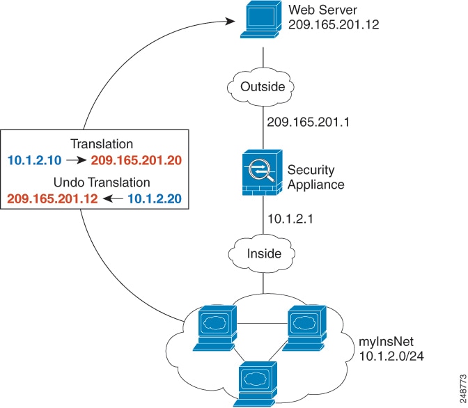
Providing Access to an Inside Web Server (Static NAT)
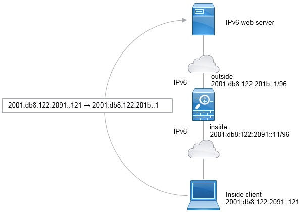
The following example performs static NAT for an inside web server. The real address is on a private network, so a public address is required. Static NAT is necessary so hosts can initiate traffic to the web server at a fixed address.

Procedure
| Step 1 |
Choose . |
| Step 2 |
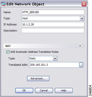
Choose , name the new network object and define the web server host address.  |
| Step 3 |
Configure static NAT for the object.  |
| Step 4 |
Click Advanced and configure the real and mapped interfaces.  |
| Step 5 |
Click OK to return to the Edit Network Object dialog box, click OK again, and then click Apply. |
NAT for Inside Hosts (Dynamic NAT) and NAT for an Outside Web Server (Static NAT)
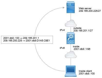
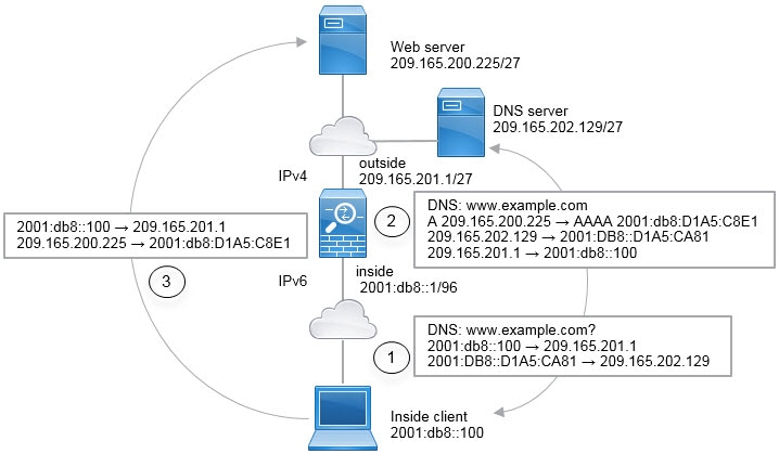
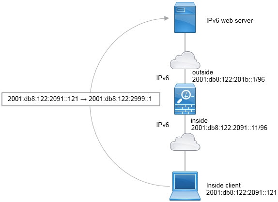
The following example configures dynamic NAT for inside users on a private network when they access the outside. Also, when inside users connect to an outside web server, that web server address is translated to an address that appears to be on the inside network.
Procedure
| Step 1 |
Choose . |
| Step 2 |
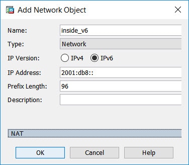
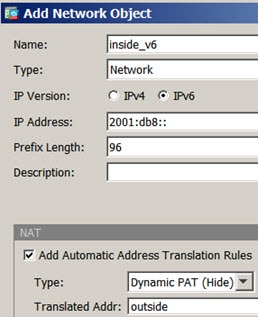
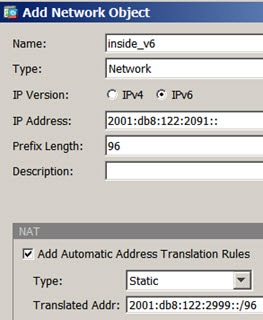
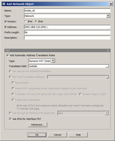
Choose , name the new network object and define the inside network.  |
| Step 3 |
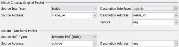
Enable dynamic NAT for the inside network.  |
| Step 4 |
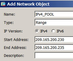
For the Translated Addr field, add a new network object for the dynamic NAT pool to which you want to translate the inside addresses by clicking the browse button.
|
| Step 5 |
Click Advanced and configure the real and mapped interfaces. |
| Step 6 |
Click OK to return to the Edit Network Object dialog box, click then click OK again to return to the NAT Rules table. |
| Step 7 |
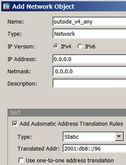
Choose and create an object for the outside web server.  |
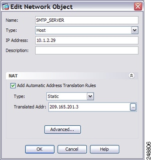
| Step 8 |
Configure static NAT for the web server.  |
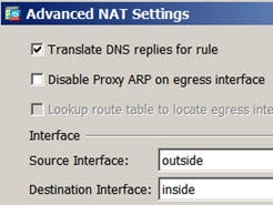
| Step 9 |
Click Advanced and configure the real and mapped interfaces.  |
| Step 10 |
Click OK to return to the Edit Network Object dialog box, click OK again, and then click Apply. |


Inside Load Balancer with Multiple Mapped Addresses (Static NAT, One-to-Many)
The following example shows an inside load balancer that is translated to multiple IP addresses. When an outside host accesses one of the mapped IP addresses, it is untranslated to the single load balancer address. Depending on the URL requested, it redirects traffic to the correct web server.

Procedure
| Step 1 |
Choose . |
| Step 2 |
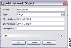
Choose , name the new network object and define the load balancer address. 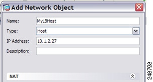 |
| Step 3 |
Enable static NAT for the load balancer: 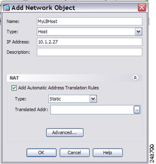 |
| Step 4 |
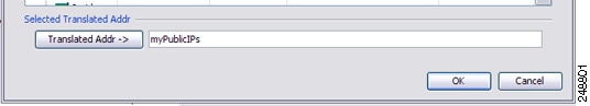
For the Translated Addr field, add a new network object for the static NAT group of addresses to which you want to translate the load balancer address by clicking the browse button.
|
| Step 5 |
Click Advanced and configure the real and mapped interfaces. 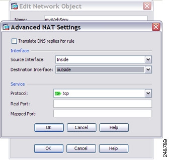 |
| Step 6 |
Click OK to return to the Edit Network Object dialog box, click OK again, and then click Apply. |
Single Address for FTP, HTTP, and SMTP (Static NAT-with-Port-Translation)
The following static NAT-with-port-translation example provides a single address for remote users to access FTP, HTTP, and SMTP. These servers are actually different devices on the real network, but for each server, you can specify static NAT-with-port-translation rules that use the same mapped IP address, but different ports.

Procedure
| Step 1 |
Choose . |
| Step 2 |
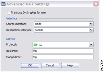
Configure the static network object NAT with port translation rule for the FTP server.
|
| Step 3 |
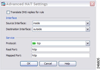
Configure the static network object NAT with port translation rule for the HTTP server.
|
| Step 4 |
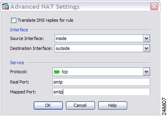
Configure the static network object NAT with port translation rule for the SMTP server.
|


 Feedback