Overview of VLAN Handoff
IP interworking pseudowire enables the service provider to terminate the TDM circuit early in the network and transport the IP payload on HDLC, PPP, or MLPPP links to the Ethernet network.
The documentation set for this product strives to use bias-free language. For the purposes of this documentation set, bias-free is defined as language that does not imply discrimination based on age, disability, gender, racial identity, ethnic identity, sexual orientation, socioeconomic status, and intersectionality. Exceptions may be present in the documentation due to language that is hardcoded in the user interfaces of the product software, language used based on RFP documentation, or language that is used by a referenced third-party product. Learn more about how Cisco is using Inclusive Language.
|
Feature Name |
Release |
Description |
|---|---|---|
| CEM and IP IW Feature Parity for NCS4200-1T8S-20CS and NCS4200-3GMS Interface Modules |
Cisco IOS XE Bengaluru 17.4.1 |
Support for IPv4 and IPv6 with VLAN handoff for both cross connect and local connect on NCS4200-1T8S-20CS and NCS4200-3GMS Interface Module. |
|
IP Interworking with VLAN Handoff |
Cisco IOS XE Amsterdam 17.3.1 |
VLAN handoff enables the support for IP interworking Pseudowire. IP interworking Pseudowire enables the service provider to terminate the TDM circuit early in the network and transport the IP payload on HDLC, PPP, or MLPPP links, over the MPLS core to the Ethernet network. |
This module describes the configuration of the VLAN handoff, which is an extension of the IP interworking pseudowire. The VLAN handoff enables the support for IP interworking pseudowire between HDLC, PPP, or MLPPP channel links to Ethernet virtual circuits (EVC).
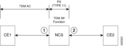
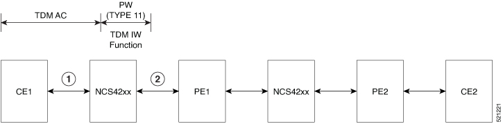
IP interworking pseudowire enables the service provider to terminate the TDM circuit early in the network and transport the IP payload on HDLC, PPP, or MLPPP links to the Ethernet network.
|
1 |
Terminate the circuit locally. IP keyword extracts the IP packets and transports it over PW and creates PW (Type 11) |
2 |
IP PW (Type 11) terminated |
Ingress logical interface range must be reserved, with not more than 4K EVCs that can be supported per ASIC. This reduces the EVC scale from 16K to 8K, with a maximum of 4K EVCs per ASIC.
You can configure only a maximum of 3998 serial interface or Interworking Multiservice Gateway (iMSG).
For a ping to work, resolve the ARP from the Ethernet interface.
VLAN handoff with a local connect over HDLC, PPP, or MLPPP is not supported when configured with port channel.
Only IPv4 is supported until Cisco IOS XE Amsterdam 17.3.1.
Use the enable_tdm_to_ip_iw command to enable the SDM template.
Router# config terminal
Router(config)# sdm prefer enable_tdm_to_ip_iw
Reload the router after you enable the template.
The new template is added and the ROMMON variable is set to 28.
TDM_TO_IP_FEAT_EXT_TEMPLATE = 28 Note |
You must reload the router for the new template to be effective. |
Interface module must be free from all configurations.
|
Step 1 |
Configure the serial or MLPPP interface on a customer edge (CE). To configure the interface on CE1, enter the following commands: |
||
|
Step 2 |
Configure the serial or MLPPP interface on a provide edge (PE). To configure the interface on PE, enter the following commands: |
||
|
Step 3 |
Configure service instance on the Ethernet interface. To configure service instance on the Ethernet interface, enter the following commands:
|
||
|
Step 4 |
Bind the service instance and the serial interface under L2VPN xconnect. To create L2VPN for local connect and bind the service instance and serial interface, enter the following commands: |
||
|
Step 5 |
Configure the service instance on CE2 to terminate the traffic on BDI or VLAN. To configure the service instance, enter the following commands: |
The following is a sample VLAN handoff configuration for CE and PE respectively.
Router# show running-config | sec 4/0/0
controller SONET 4/0/0
framing sonet
clock source line
!
sts-1 1
mode vt-15
vtg 1 t1 1 channel-group 0 timeslots 1-24
Router# show ip int brief | i Se
Serial4/0/0.1/1/1:0 10.12.12.1 YES manual up up
Serial Interface Configuration
platform enable controller MediaType 0/4/17 oc12
controller MediaType 0/4/17
mode sonet
controller SONET 0/4/17
no snmp trap link-status
rate OC12
no ais-shut
alarm-report all
threshold sf-ber 3
clock source internal
!
sts-1 1
clock source internal
mode vt-15
vtg 1 t1 1 channel-group 0 timeslots 1-24
!
Gigabit Ethernet Configuration
interface TenGigabitEthernet0/1/1
no ip address

service instance 10 ethernet
encapsulation dot1q 10
rewrite ingress tag pop 1 symmetric
!
end
L2vpn xconnect
l2vpn xconnect context vlan_handoff_10
interworking ip
member Serial0/4/17.1
member TenGigabitEthernet0/1/1 service-instance 10
Configuration on CE2
interface TenGigabitEthernet0/12/1
no ip address
service instance 10 ethernet
encapsulation dot1q 10
rewrite ingress tag pop 1 symmetric
bridge-domain 10
!
end
interface BDI10
ip address 10.12.12.2 255.0.0.0
no shut
Router# show ip int brief | i BDI
BDI10 10.12.12.2 YES manual up up
Interface module must be free from all configurations.
|
Step 1 |
Configure the serial interface on CE1. To configure the serial interface on CE1, enter the following commands: |
||
|
Step 2 |
Perform the following configurations on PE1:
|
||
|
Step 3 |
Perform the following configurations on PE2: |
||
|
Step 4 |
Terminate the serial interface on the Ethernet interface. Terminate the serial interface on the Ethernet interface, enter the following commands: |
|
Feature Name |
Release |
Description |
|---|
Interface module must be free from all configurations.
|
Step 1 |
Configure the serial or MLPPP interface on a customer edge (CE). To configure the interface on CE1, enter the following commands: |
||
|
Step 2 |
Configure the serial or MLPPP interface on a provide edge (PE). To configure the interface on PE, enter the following commands: |
||
|
Step 3 |
Configure service instance on the Ethernet interface. To configure service instance on the Ethernet interface, enter the following commands:
|
||
|
Step 4 |
Bind the service instance and the serial interface under L2VPN xconnect. To create L2VPN for local connect and bind the service instance and serial interface, enter the following commands: |
||
|
Step 5 |
Configure the service instance on CE2 to terminate the traffic on BDI or VLAN. To configure the service instance, enter the following commands:
|
Interface module must be free from all configurations.
|
Step 1 |
Configure the serial interface on CE1. To configure the serial interface on CE1, enter the following commands: |
||
|
Step 2 |
Perform the following configurations on PE1:
|
||
|
Step 3 |
Perform the following configurations on PE2: |
||
|
Step 4 |
Terminate the serial interface on the Ethernet interface. To terminate the serial interface on the Ethernet interface, enter the following commands: |
 Feedback