Deploying in Microsoft Azure

Prerequisites and Guidelines

Before you proceed with deploying the Nexus Dashboard cluster in Microsoft Azure, you must:

  • Ensure that the Azure form factor supports your scale and services requirements.

    Scale and services support and co-hosting vary based on the cluster form factor. You can use the Nexus Dashboard Capacity Planning tool to verify that the cloud form factor satisfies your deployment requirements.

  • Review and complete the general prerequisites described in the Deployment Overview.

  • Review and complete any additional prerequisites described in the Release Notes for the services you plan to deploy.

  • Have appropriate access privileges for your Azure account and subscription.

  • Have created a resource group for your Nexus Dashboard cluster resources.


    Note


    The resource group must be empty and not contain any existing objects. Resource groups with existing objects cannot be used for Nexus Dashboard deployment.


    To create a resource group:

    • In the Azure portal, navigate to All Resources > Resource Groups.

    • Click +Add to create a new resource group.

    • In the Create a resource group screen, provide the name of the subscription you will use for your Nexus Dashboard cluster, the name for the resource group (for example, nd-cluster), and the region.

  • Create an SSH key pair.

    A key pair consists of a private key and a public key, you will be asked to provide the public key when creating the Nexus Dashboard nodes.


    Note


    You will need to use the same machine where you create the public key for a one-time login into each node to enable general SSH login during cluster deployment procedure.


    Creating SSH keys is described in Generating an SSH Key Pair in Linux or MacOS and Generating an SSH Key Pair in Windows sections below.

Generating an SSH Key Pair in Linux or MacOS

These procedures describe how to generate an SSH public and private key pair in Linux or MacOS. For instructions on generate an SSH public and private key pair in Windows, see Generating an SSH Key Pair in Windows.

Procedure


Step 1

On your Linux virtual machine or Mac, create a public and private key pair using ssh-keygen, directing the output to a file.

# ssh-keygen -f filename

For example:

# ssh-keygen -f azure_key

Output similar to the following appears. Press the Enter key without entering any text when you are asked to enter a passphrase (leave the field empty so that there is no passphrase).

Generating public/private rsa key pair.
Enter passphrase (empty for no passphrase):
Enter same passphrase again:
Your identification has been saved in azure_key.
Your public key has been saved in azure_key.pub.
The key fingerprint is:
SHA256:gTsQIIAadjgNsgcguifIloh4XGpVWMdcXVV6U0dyBNs
...

Step 2

Locate the public and private key files that you saved.

# ls

Two files should be displayed, where:

  • The file with the .pub suffix contains the public key information

  • The file with the same name, but with no suffix, contains the private key information

For example, if you directed the output to a file named azure_key, you should see the following output:

# ls
azure_key
azure_key.pub

In this case:

  • The azure_key.pub file contains the public key information

  • The azure_key file contains the private key information

Step 3

Open the public key file and copy the public key information from that file, without the username@hostname information at the end.

Note


The private key file is not used in the installation process. However, you might need it for other reasons, such as logging into your Nexus Dashboard nodes through SSH.


Generating an SSH Key Pair in Windows

These procedures describe how to generate an SSH public and private key pair in Windows. For instructions on generate an SSH public and private key pair in Linux, see Generating an SSH Key Pair in Linux or MacOS.

Procedure


Step 1

Download and install the PuTTY Key Generator (puttygen):

https://www.puttygen.com/download-putty

Step 2

Run the PuTTY Key Generator by navigating to Windows > Start Menu > All Programs > PuTTY > PuTTYgen.

You will see a window for the PuTTY Key Generator on your screen.
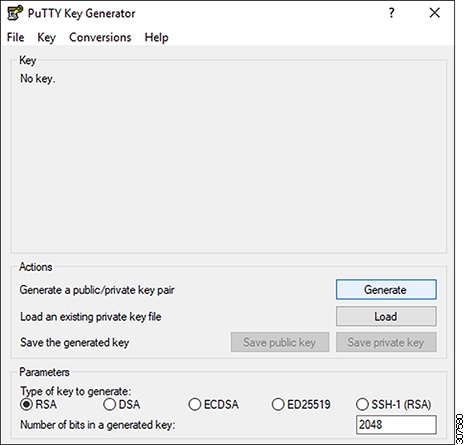
Step 3

Click Generate.

A screen appears, asking you to move the mouse over the blank area to generate a public key.

Step 4

Move your cursor around the blank area to generate random characters for a public key.
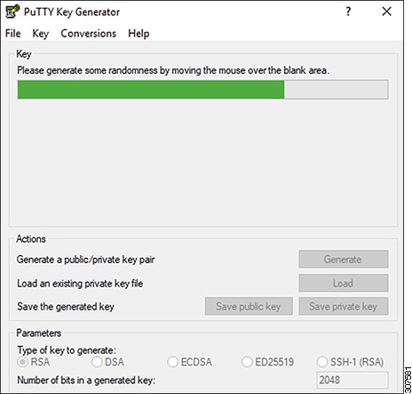
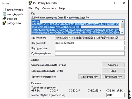
Step 5

Save the public key.

  1. Navigate to a folder on your laptop where you want to save the public key file and create a text file for this public key.

  2. Copy the information in the PuTTY Key Generator.

    Copy the public key information in the window, with these inclusions and exclusions:

    • Including the ssh-rsa text at the beginning of the public key.

    • Excluding the following text string at the end:

      == rsa-key-<date-stamp>

      Truncate the key so that it does not include the == rsa-key-<date-stamp> text string at the end.

      Note


      In the next set of procedures, you will paste the public key information into the Azure ARM template. If the form does not accept the key in this format, add == back to the end of the key, as this format is required in some regions.

    If the key is not in the correct format, the Nexus Dashboard will not complete its installation.

  3. Paste the information in the public key text file that you created in 5.a and save the file, giving it a unique file name.

    This public key text file will now contain a key that is on a single line of text. You will need the information in this public key text file in the next set of procedures.

    Note


    Do not save the public key using the Save public key option in the PuTTY Key Generator. Doing so saves the key in a format that has multiple lines of text, which is not compatible with the Nexus Dashboard deployment process.

Step 6

Save the private key.

  1. Click Save private key.

    A screen appears, asking if you want to save the file without a passphrase. Click Yes on this screen.

  2. Navigate to a folder on your laptop and save the private key file, giving it a unique file name.

    Note


    The private key file is not used in the installation process. However, you might need it for other reasons, such as logging into your Nexus Dashboard nodes through SSH.


Deploying Nexus Dashboard in Azure

This section describes how to deploy Cisco Nexus Dashboard cluster in Microsoft Azure.

Before you begin

Procedure


Step 1

Subscribe to Cisco Nexus Dashboard product in Azure Marketplace.

  1. Log into your Azure account and browse to https://azuremarketplace.microsoft.com

  2. In the search field, type Cisco Nexus Dashboard and select the option that is presented.

    You will be re-directed to the Nexus Dashboard Azure Marketplace page.

  3. Click Get it now.

  4. In the Select a plan dropdown, select the version and click Create.

Step 2

Provide Basic information.

  1. From the Subscription dropdown, select the subscription you want to use for this.

  2. From the Resource group dropdown, select the resource group you created for this as part of Prerequisites and Guidelines.

  3. From the Region dropdown, select the region where the template will be deployed.

  4. In the Password and Confirm Password fields, provide the admin password for the nodes.

    This password will be used for the Nexus Dashboard's rescue-user login, as well as the initial password for the GUI's admin user.

    Note


    You must provide the same password for all nodes or the cluster creation will fail.

  5. In the SSH public key field, paste the public key from the key pair you generated as part of the Prerequisites and Guidelines section.

  6. Click Next to proceed to the next screen.

Step 3

Provide ND Settings information.

  1. Provide the Cluster Name.

  2. In the Image Version dropdown, verify that the correct version is selected.

  3. In the Virtual Network Name field, provide the name for a VNET that will be created for your cluster.

    The VNET must not already exist and will be created for you during deployment. If you provide an already existing VNET, the deployment cannot proceed.

  4. In the Subnet Address Prefix field, provide a subnet within the VNET.

    The subnet must be a /24 subnet and it must be different from the default VNET subnet you defined when creating the VNET.

  5. In the External Subnets field, provide the external network allowed to access the cluster.

    For example, 0.0.0.0/0 to be able to access the cluster from anywhere.

  6. Click Next to proceed to the next screen.

Step 4

In the Review + create page, review information and click Create to deploy the cluster.

Step 5

Wait for the deployment to complete, then start the VMs.

Step 6

Note down all nodes' public IP addresses.

After all instances are deployed, navigate to the Azure console, select each VM, and note down all nodes' public IP addresses. You will provide this information to the GUI bootstrap wizard in the following steps.

Also note which is the "first" node, which will be indicated by the node's VM name vm-node1-<cluster-name>. You will use this node's public IP address to complete cluster configuration.

Step 7

Enable password-based login on all nodes.

By default only key-based login is enabled for each node. To be able to SSH into the nodes using a password, as required by the GUI setup wizard, you will need to explicitly enable password-based logins.

Note


You must enable password-based login on all nodes before proceeding to cluster bootstrap described in the following steps or you will not be able to complete the cluster configuration.

  1. SSH in to one of the nodes as rescue-user.

    Note


    You must use the same machine as you used to create the public key for the deployment during the Prerequisites and Guidelines section.

    You can log in as rescue-user using the password you provided in template's Basic settings:

    # ssh rescue-user@<node-public-ip>
  2. Enable password-based login.

    # acs login-prompt enable
  3. Repeat this step for the other two nodes.

Step 8

Open your browser and navigate to https://<first-node-public-ip> to open the GUI.

Note


You must use the public IP address of the first node (vm-node1-<cluster-name>) or cluster configuration cannot be completed.

The rest of the configuration workflow takes place from the first node's GUI. You do not need to log in to or configure the other two nodes directly.

Enter the password you provided during template deployment and click Begin Setup

Step 9

Enter the password you provided for the first node and click Begin Setup.

Step 10

Provide the Cluster Details.

In the Cluster Details screen of the initial setup wizard, provide the following information:

  1. Provide the Cluster Name for this Nexus Dashboard cluster.

  2. Click +Add NTP Host to add one or more NTP servers.

    You must provide an IP address, fully qualified domain name (FQDN) are not supported.

    After you enter the IP address, click the green checkmark icon to save it.

  3. Click +Add DNS Provider to add one or more DNS servers.

    After you enter the IP address, click the green checkmark icon to save it.

  4. Provide a Proxy Server.

    For clusters that do not have direct connectivity to Cisco cloud, we recommend configuring a proxy server to establish the connectivity, which will allow you to mitigate risk from exposure to non-conformant hardware and software in your fabrics.

    If you want to skip proxy configuration, click the information (i) icon next to the field, then click Skip.

  5. (Optional) If your proxy server required authentication, change Authentication required for Proxy to Yes and provide the login credentials.

  6. (Optional) Expand the Advanced Settings category and change the settings if required.

    Under advanced settings, you can configure the following:

    • Provide one or more search domains by clicking +Add DNS Search Domain.

      After you enter the IP address, click the green checkmark icon to save it.

    • Provide custom App Network and Service Network.

      The application overlay network defines the address space used by the application's services running in the Nexus Dashboard. The field is pre-populated with the default 172.17.0.1/16 value.

      The services network is an internal network used by the Nexus Dashboard and its processes. The field is pre-populated with the default 100.80.0.0/16 value.

      Application and Services networks are described in the Prerequisites and Guidelines section earlier in this document.

  7. Click Next to continue.

Step 11

In the Node Details screen, provide the node's information.

  1. Click the Edit button next to the first node.

  2. Provide the node's Name.

    The Management Network and Data Network information will be already populated from the VNET subnet you have configured before deploying the cluster.

    The cluster creates six subnets from the given VNET, from which the data and management networks will be allocated for the cluster's three nodes.

  3. Leave IPv6 addresses and VLAN fields blank.

    Cloud Nexus Dashboard clusters do not support these options.

  4. Click Save to save the changes.

Step 12

Click Add Node to add the second node to the cluster.

The Node Details window opens.

  1. Provide the node's Name.

  2. In the Credentials section, provide the node's Public IP Address and the password you provided during template deployment, then click Verify.

    The IP address and password are used to pull that node's Management Network and Data Network information, which will be populated in the fields below.

  3. Click Save to save the changes.

Step 13

Repeat the previous step to add the 3rd node.

Step 14

Click Next to continue.

Step 15

In the Confirmation screen, review the entered information and click Configure to create the cluster.

During the node bootstrap and cluster bring-up, the overall progress as well as each node's individual progress will be displayed in the UI.

It may take up to 30 minutes for the cluster to form and all the services to start. When cluster configuration is complete, the page will reload to the Nexus Dashboard GUI.

Step 16

Verify that the cluster is healthy.

It may take up to 30 minutes for the cluster to form and all the services to start.

After all three nodes are ready, you can log in to any one node via SSH and run the following command to verify cluster health:

  1. Verify that the cluster is up and running.

    You can check the current status of cluster deployment by logging in to any of the nodes and running the acs health command.

    While the cluster is converging, you may see the following outputs:

    $ acs health
    k8s install is in-progress
    $ acs health
    k8s services not in desired state - [...]
    $ acs health
    k8s: Etcd cluster is not ready
    When the cluster is up and running, the following output will be displayed:
    $ acs health
    All components are healthy
  2. Log in to the Nexus Dashboard GUI.

    After the cluster becomes available, you can access it by browsing to any one of your nodes' management IP addresses. The default password for the admin user is the same as the rescue-user password you chose for the first node of the Nexus Dashboard cluster.

Step 17

Update the nodes' security group with required ports.

This step describes how to update the Nexus Dashboard nodes' instances with the required port configuration for on-boarding Cisco NDFC sites. If you do not plan on on-boarding any NDFC sites to your Nexus Dashboard cluster, you can skip this step.

  1. In the Azure portal, navigate to the resource group where you deployed your Nexus Dashboard.

    This is the same resource group you selected in Step 2.

  2. Select the security group attached to the nodes' data interfaces.

    The name of the security group will begin with nsg-data-<region>-....

  3. In the security group's setting navigation bar, select Inbound security rules.

  4. Click +Add to add a new inbound security rule, then provide the details to allow inbound communication on port 443.

    Provide the following information for the new rule:

    • For Source, select Any.

    • For Source port ranges, enter 443.

    • For Destination, select Any.

    • For Destination port ranges, enter 443.

    • For Protocol, choose TCP.

    • For Action, choose Allow.

    • For Priority, choose a priority between 300 and 320.

      For example, 305.

    • Provide a Name for the rule.

  5. Click +Add to add a new inbound security rule, then provide the details to allow inbound communication on port 9092.

    Repeat the previous substep to add another rule with the following details:

    • For Source, select Any.

    • For Source port ranges, enter 9092.

    • For Destination, select Any.

    • For Destination port ranges, enter 9092.

    • For Protocol, choose TCP.

    • For Action, choose Allow.

    • For Priority, choose a priority between 300 and 320.

      For example, 310.

    • Provide a Name for the rule.