Servicing the Compute Node

This chapter contains the following topics:

Removing and Installing the Compute Node Cover

The top cover for the Cisco UCS X210c M7 compute node can be removed to allow access to internal components, some of which are field-replaceable. The green button on the top cover releases the compute node so that it can be removed from the chassis.

Removing a Compute Node Cover

To remove the cover of the UCS X210c M7 compute node, follow these steps:

Procedure


Step 1

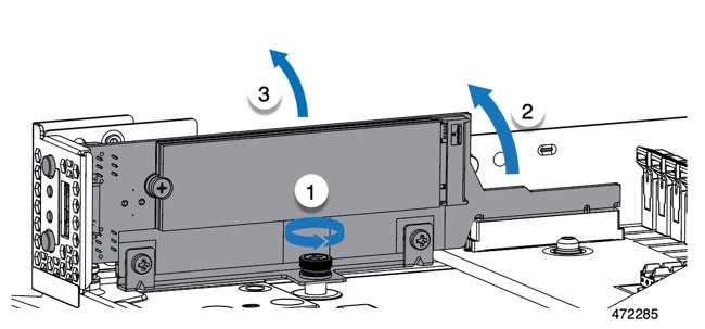
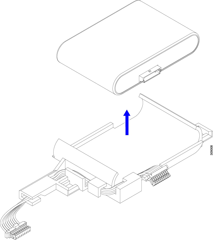
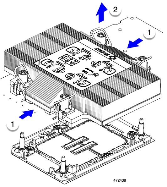
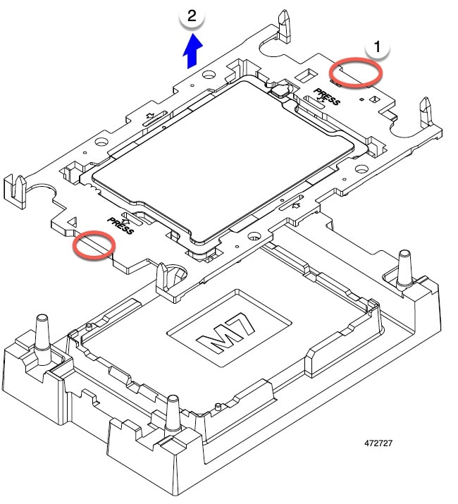
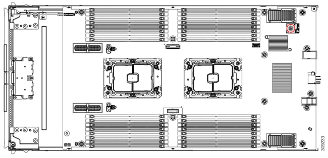
Press and hold the button down (1, in the figure below).

Step 2

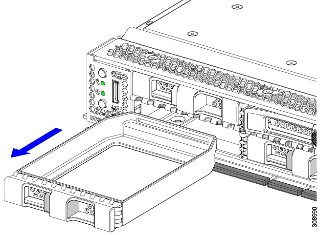
While holding the back end of the cover, slide it back, then pull it up (2).

By sliding the cover back, you enable the front edge to clear the metal lip on the rear of the front mezzanine module.


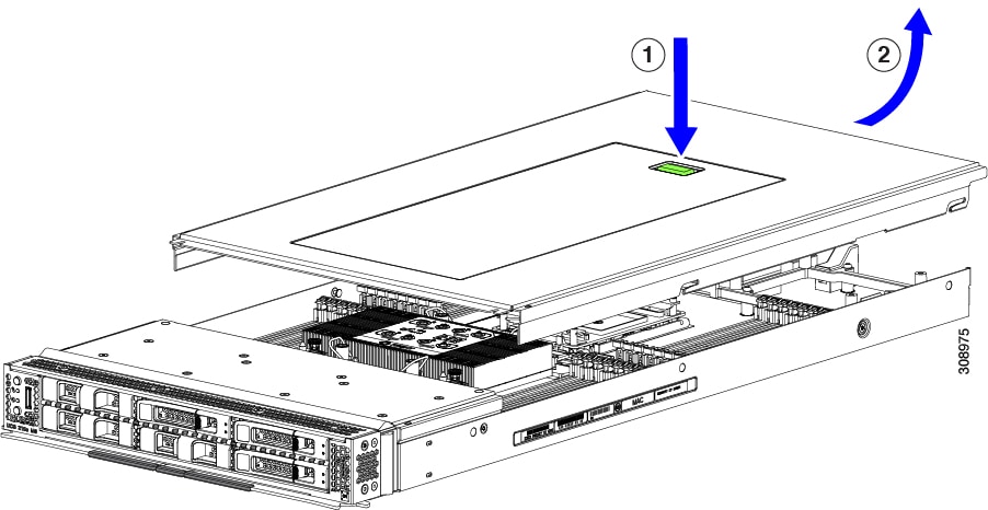
Installing a Compute Node Cover

Use this task to install a removed top cover for the UCS X210c M7 compute node.

Procedure


Step 1

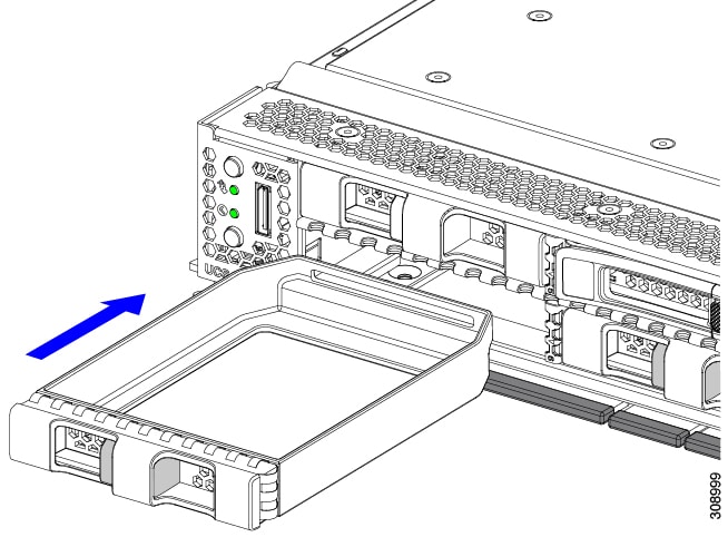
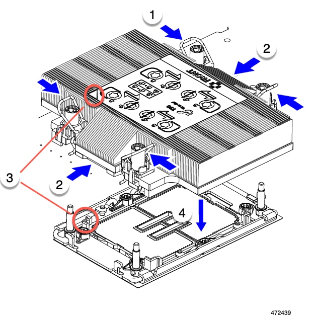
Insert the cover angled so that it hits the stoppers on the base.

Step 2

Lower the compute node's cover until it reaches the bottom.
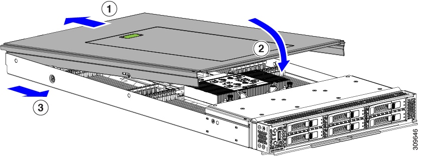
Step 3

Keeping the compute node's cover flat, slide it forward until the release button clicks.


Internal Components

The following illustration shows the location of internal components on the compute node.

1

Front mezzanine module slot

2

Mini-Storage module connector, which supports one mini-storage module with up to two M.2 SATA or M.2 NVMe drives.

3

Front mezzanine slot connectors

4

CPU 1, which supports either Fourth or Fifth Generation Intel Xeon Scalable Processors.

5

DIMM Slots

6

Debug connector

Only for use by Cisco personnel.

7

CPU 2, which supports either Fourth or Fifth Generation Intel Xeon Scalable Processors.

8

Motherboard USB Connector

9

TPM Connector

10

Rear mezzanine slot, which supports X-Series mezzanine cards, such as VIC 15422.

11

Bridge Card slot, which connects rear mezzanine slot and the mLOM/VIC slot

12

mLOM/VIC slot that supports zero or one Cisco VIC or Cisco X-Series 100 Gbps mLOM

Replacing a Drive

You can remove and install some drives without removing the compute node from the chassis. All drives have front-facing access, and they can be removed and inserted by using the ejector handles.

The SAS/SATA or NVMe drives supported in this compute node come with the drive sled attached. Spare drive sleds are not available.

Before upgrading or adding a drive to a running compute node, check the service profile through Cisco UCS management software and make sure the new hardware configuration will be within the parameters allowed by the management software.


Caution


To prevent ESD damage, wear grounding wrist straps during these procedures.


NVMe SSD Requirements and Restrictions

For 2.5-inch NVMe SSDs, be aware of the following:

  • NVMe 2.5 SSDs support booting only in UEFI mode. Legacy boot is not supported.

    UEFI boot mode can be configured through Cisco UCS management software. For information about Cisco UCS management software, see Compute Node Configuration.

  • NVMe U.2 PCIe SSDs cannot be controlled with a SAS RAID controller because NVMe SSDs interface with the server via the PCIe bus.

  • NVME U.3 SSDs connect to the RAID controller so RAID is supported for these drives.

  • UEFI boot is supported in all supported operating systems.

Enabling Hot Plug Support

Surprise and OS-informed hot plug is supported with the following conditions:

  • VMD must be enabled to support hot plug.

  • VMD must be enabled before installing an OS on the drive.

  • If VMD is not enabled, surprise hot plug is not supported, and you must do OS-informed hotplug instead.

  • VMD is required for both surprise hot plug and drive LED support.

Removing a Drive

Use this task to remove a SAS/SATA or NVMe drive from the compute node.


Caution


Do not operate the system with an empty drive bay. If you remove a drive, you must reinsert a drive or cover the empty drive bay with a drive blank.


Procedure


Step 1

Push the release button to open the ejector, and then pull the drive from its slot.

Caution


To prevent data loss, make sure that you know the state of the system before removing a drive.

Step 2

Place the drive on an antistatic mat or antistatic foam if you are not immediately reinstalling it in another compute node.

Step 3

Install a drive blanking panel to maintain proper airflow and keep dust out of the drive bay if it will remain empty.


What to do next

Cover the empty drive bay. Choose the appropriate option:

Installing a Drive


Caution


For hot installation of drives, after the original drive is removed, you must wait for 20 seconds before installing a drive. Failure to allow this 20-second wait period causes the Cisco UCS management software to display incorrect drive inventory information. If incorrect drive information is displayed, remove the affected drive(s), wait for 20 seconds, then reinstall them.


To install a SAS/SATA or NVMe drive in the compute node, follow this procedure:

Procedure


Step 1

Place the drive ejector into the open position by pushing the release button.

Step 2

Gently slide the drive into the empty drive bay until it seats into place.

Step 3

Push the drive ejector into the closed position.

You should feel the ejector click into place when it is in the closed position.


Basic Troubleshooting: Reseating a SAS/SATA Drive

Sometimes it is possible for a false positive UBAD error to occur on SAS/SATA HDDs installed in the compute node.

  • Only drives that are managed by the UCS MegaRAID controller are affected.

  • Both SFF and LFF form factor drives can be affected.

  • Drives can be affected regardless of whether they are configured for hot plug or not.

  • The UBAD error is not always terminal, so the drive is not always defective or in need of repair or replacement. However, it is also possible that the error is terminal, and the drive will need replacement.

Before submitting the drive to the RMA process, it is a best practice to reseat the drive. If the false UBAD error exists, reseating the drive can clear it. If successful, reseating the drive reduces inconvenience, cost, and service interruption, and optimizes your compute node uptime.


Note


Reseat the drive only if a UBAD error occurs. Other errors are transient, and you should not attempt diagnostics and troubleshooting without the assistance of Cisco personnel. Contact Cisco TAC for assistance with other drive errors.


To reseat the drive, see Reseating a SAS/SATA Drive.

Reseating a SAS/SATA Drive

Sometimes, SAS/SATA drives can throw a false UBAD error, and reseating the drive can clear the error.

Use the following procedure to reseat the drive.


Caution


This procedure might require powering down the server. Powering down the server will cause a service interruption.


Before you begin

Before attempting this procedure, be aware of the following:

  • Before reseating the drive, it is a best practice to back up any data on it.

  • When reseating the drive, make sure to reuse the same drive bay.

    • Do not move the drive to a different slot.

    • Do not move the drive to a different server.

    • If you do not reuse the same slot, the Cisco UCS management software (for example, Cisco IMM) might require a rescan/rediscovery of the server.

  • When reseating the drive, allow 20 seconds between removal and reinsertion.

Procedure

Step 1

Attempt a hot reseat of the affected drive(s).

For a front-loading drive, see Removing a Drive.

Note


While the drive is removed, it is a best practice to perform a visual inspection. Check the drive bay to ensure that no dust or debris is present. Also, check the connector on the back of the drive and the connector on the inside of the server for any obstructions or damage.

Also, when reseating the drive, allow 20 seconds between removal and reinsertion.

Step 2

During boot up, watch the drive's LEDs to verify correct operation.

See Interpreting LEDs.

Step 3

If the error persists, cold reseat the drive, which requires a server power down. Choose the appropriate option:

  1. Use your server management software to gracefully power down the server.

    See the appropriate Cisco UCS management software documentation.

  2. If server power down through software is not available, you can power down the server by pressing the power button.

    See Compute Node Front Panel.

  3. Reseat the drive as documented in Step 1.

  4. When the drive is correctly reseated, restart the server, and check the drive LEDs for correct operation as documented in Step 2.

Step 4

If hot and cold reseating the drive (if necessary) does not clear the UBAD error, choose the appropriate option:

  1. Contact Cisco Systems for assistance with troubleshooting.

  2. Begin an RMA of the errored drive.


Removing a Drive Blank

A maximum of six SAS/SATA or NVMe drives are contained in the front mezzanine storage module as part of the drive housing. The drives are front facing, so removing them does not require any disassembly.

Use this procedure to remove a drive blank from the compute node.

Procedure


Step 1

Grasp the drive blank handle.

Step 2

Slide the drive blank out of the slot.


What to do next

Cover the empty drive bay. Choose the appropriate option:

Installing a Drive Blank

Use this task to install a drive blank.

Procedure


Step 1

Align the drive blank so that the sheet metal is facing down.

Step 2

Holding the blank level, slide it into the empty drive bay.


Replacing the Front Mezzanine Module

The front mezzanine module is a steel cage that contains the compute node's storage devices or a mix of GPUs and drives. The front mezzanine storage module can contain any of the following storage configurations:

  • NVMe drives, U.2 and U.3

  • SAS/SATA drives

  • Cisco T4 GPUs plus up to two U.2 or U.3 NVMe drives

In the front mezzanine slot, the compute node can use one of the following front storage module options:

  • A front mezzanine blank (UCSX-X10C-FMBK) for systems without local disk requirements.

  • Compute Pass Through Controller (UCSX-X10C-PT4F): supports up to six hot pluggable 15mm NVMe drives directly connected to CPU 1.

  • MRAID Storage Controller Module (UCSX-X10C-RAIDF):

    • Supports a mixed drive configuration of up to six SAS, SATA, and U.2 NVMe (maximum of four) drives. With a mix of SAS/SATA and NVMe, U.2 NVMe drives are supported in slots one through four only.

    • Provides HW RAID support for SAS/SATA drives in multiple RAID groups and levels.

    • Supports NVMe U.3 drives in slots 1 through 6 and can be configured into multiple RAID groups and levels similar to SAS/SATA drives.

    • Supports a mix of SAS/SATA and NVMe U.3 drives behind the MRAID controller. However, these NVMe drives and SAS/SATA drives cannot be combined in the same RAID group.

      NVME U.3 drives can be combined to make RAID groups separately. Also, SAS/SATA drives can be formed into different RAID groups, and the different RAID groups can co-exist in the same MRAID storage setup.

  • The front mezzanine module also contains the SuperCap module. For information about replacing the SuperCap module, see Replacing the SuperCap Module.


    Note


    The SuperCap module is only needed when the MRAID Storage Controller module (UCSX-X10C-RAIDF) is installed.


  • A compute and storage option (UCSX-X10C-GPUFM) consisting of a GPU adapter supporting zero, one, or two Cisco T4 GPUs (UCSX-GPU-T4-MEZZ) plus zero, one, or two U.2 or U.3 NVMe SSDs.

The front mezzanine module can be removed and installed as a whole unit to give easier access to the storage drives that it holds. Or, you can leave the front mezzanine module installed because SAS/SATA and the NVMe drives are accessible directly through the front of the front mezzanine panel and are hot pluggable.

To replace the front mezzanine module, use the following topics:

Front Mezzanine Module Guidelines

Be aware of the following guidelines for the front mezzanine slot:

  • For MRAID Storage Controller Module (UCSX-X10C-RAIDF), M.2 Mini Storage, and NVMe storage, only UEFI boot mode is supported.

  • The compute node has a configuration option that supports up to 2 Cisco T4 GPUs (UCSX-GPU-T4-MEZZ) and up to two Cisco U.2 NVMe drives in the front mezzanine slot. This optional configuration is interchangeable with the standard configuration of all drives. For information about the GPU-based front mezzanine option, see the Cisco UCS X10c Front Mezzanine GPU Module Installation and Service Guide.

Removing the Front Mezzanine Module

Use the following procedure to remove the front mezzanine module. This procedure applies to the following modules:

  • Front mezzanine blank (UCSX-X10C-FMBK)

  • Compute Pass Through Controller (UCSX-X10C-PT4F)

  • MRAID Storage Controller Module (UCSX-X10C-RAIDF)

Before you begin

To remove the front mezzanine module, you need a T8 screwdriver and a #2 Phillips screwdriver.

Procedure


Step 1

If the compute node's cover is not already removed, remove it now. Remove the compute node cover.

See Removing a Compute Node Cover.

Step 2

Remove the securing screws:

  1. Using a #2 Phillips screwdriver, loosen the two captive screws on the top of the front mezzanine module.

    Note


    This step may be skipped if removing the front mezzanine blank (UCSX-X10C-FMBK).

  2. Using a T8 screwdriver, remove the two screws on each side of the compute node that secure the front mezzanine module to the sheet metal.

Step 3

Making sure that all the screws are removed, lift the front mezzanine module to remove it from the compute node.


What to do next

To install the front mezzanine module, see Installing the Front Mezzanine Module

Installing the Front Mezzanine Module

Use the following procedure to install the front mezzanine module. This procedure applies to the following modules:

  • Front mezzanine blank (UCSX-X10C-FMBK)

  • Compute Pass Through Controller (UCSX-X10C-PT4F)

  • MRAID Storage Controller Module (UCSX-X10C-RAIDF)

Before you begin

To install the front mezzanine module, you need a T8 screwdriver and a #2 Phillips screwdriver.

Procedure


Step 1

Align the front mezzanine module with its slot on the compute node.

Step 2

Lower the front mezzanine module onto the compute node, making sure that the screws and screwholes line up.

Step 3

Secure the front mezzanine module to the compute node.

  1. Using a #2 Phillips screwdriver, tighten the captive screws on the top of the front mezzanine module.

    Note


    This step may be skipped if installing the front mezzanine blank (UCSX-X10C-FMBK).

  2. Using a T8 screwdriver, insert and tighten the four screws, two on each side of the sever node.


What to do next

If you removed the drives from the front mezzanine module, reinstall them now. See Installing a Drive.

Servicing the Mini Storage Module

The compute node has a mini-storage module option that plugs into a motherboard socket to provide additional internal storage. The module sits vertically behind the left side front panel. See Internal Components.

Two configurations of mini storage module are supported, one with an integrated RAID controller card, and one without.

Replacing a Boot-Optimized M.2 RAID Controller Module or NVMe Pass-Through Module

The Cisco Boot-Optimized M.2 RAID Controller for M.2 SATA drives or the NVMe Pass-Through Controller for M.2 NVMe drives connects to the mini-storage module socket on the motherboard. Each of the following components contains two module slots for M.2 drives:

  • The Cisco UCSX Front panel with M.2 RAID controller for SATA drives (UCSX-M2-HWRD-FPS). This component has an integrated 6-Gbps SATA RAID controller that can control the SATA M.2 drives in a RAID 1 array.

  • The Cisco UCSX Front panel with M.2 Pass Through controller for NVME drives (UCSX-M2-PT-FPN). The M.2 NVMe drives are not configurable in a RAID group.

Cisco Boot-Optimized M.2 RAID Controller Considerations

Review the following considerations:

  • This controller supports RAID 1 (single volume) and JBOD mode.

  • A SATA M.2 drive in slot 1 is located on the right side, or front, of the module when installed. This drive faces the interior of the compute node. This drive is the first SATA device.

  • A SATA M.2 drive in slot 2 is located on the left side, or back, of the module when installed. This drive faces the compute node's sheet metal wall. This drive is the second SATA device.

    • The name of the controller in the software is MSTOR-RAID.

    • A drive in slot 1 is mapped as drive 253; a drive in slot 2 is mapped as drive 254.

  • When using RAID, we recommend that both SATA M.2 drives are the same capacity. If different capacities are used, the smaller capacity of the two drives is used to create a volume and the rest of the drive space is unusable.

    JBOD mode supports mixed capacity SATA M.2 drives.

  • Hot-plug replacement is not supported. The compute node must be powered off.

  • Monitoring of the controller and installed SATA M.2 drives can be done using Cisco UCS management software. They can also be monitored using other utilities such as UEFI HII, and Redfish.

  • The SATA M.2 drives can boot in UEFI mode only. Legacy boot mode is not supported.

  • If you replace a single SATA M.2 drive that was part of a RAID volume, rebuild of the volume is auto-initiated after the user accepts the prompt to import the configuration. If you replace both drives of a volume, you must create a RAID volume and manually reinstall any OS.

  • We recommend that you erase drive contents before creating volumes on used drives from another compute node. The configuration utility in the compute node BIOS includes a SATA secure-erase function.

Removing the M.2 RAID Controller Module or NVMe Pass-Through Module

This topic describes how to remove a Cisco Boot-Optimized M.2 RAID Controller or a Cisco NVMe Pass-Through Controller:

  • The Cisco UCSX Front panel with M.2 RAID controller for SATA drives (UCSX-M2-HWRD-FPS).

  • The Cisco UCSX Front panel with M.2 Pass-Through module for NVME drives (UCSX-M2-PT-FPN).

Both types of controller board have two slots, one for each M.2 drive:

  • one M.2 slot (Slot 1) for either a SATA drive (in UCSX-M2-HWRD-FPS) or an NVMe drive (in UCSX-M2-PT-FPN). The drive in this slot faces the interior of the compute node.

  • one M.2 slot (Slot 2) for either a SATA drive (in UCSX-M2-HWRD-FPS) or an NVMe drive (in UCSX-M2-PT-FPN). The drive in this slot faces the chassis sheetmetal wall.

  • Drive slot numbering differs depending on which Cisco management tool you are using and which component is being managed.

    Component

    Cisco Management Tool

    Intersight (IMM)

    UCS Manager (UCSM)

    RAID Controller

    Slot 1 contains Drive 253

    Slot 2 contains Drive 254

    Slot 1 contains Drive 253

    Slot 2 contains Drive 254

    NVMe Pass-Through Controller

    Slot 1 contains Drive 253

    Slot 2 contains Drive 254

    Slot 1 contains Drive 32

    Slot 2 contains Drive 33

Each controller can be populated with up to two M.2 drives of the correct type, either SATA for the RAID controller or NVMe for the Pass-Through controller. Single M.2 SATA or NVMe drives are supported. You cannot mix M.2 drive types in the same controller.

To remove the controller or the M.2 drives, the front mezzanine module must be removed first.

Procedure

Step 1

Remove the controller from the compute node:

  1. Decommission, power off, and remove the compute node from the chassis.

  2. Remove the top cover from the compute node as described in Removing and Installing the Compute Node Cover.

Step 2

If you have not already done so, remove the front mezzanine module.

See Removing the Front Mezzanine Module.

Step 3

Remove the controller.

  1. Locate the controller in the front corner of the server along the compute node's sidewall.

  2. Using a #2 Phillips screwdriver, loosen the captive screw that secures the module to the motherboard.

  3. At the end opposite the front panel, grasp the module and pull up in an arc to disconnect the controller from its motherboard socket.

  4. Holding the controller at an angle, slide it away from the front panel and lift it up to disengage the LEDs and buttons from their cutouts in the front panel.

    Caution


    If you feel resistance while lifting the controller, make sure that the LEDs and buttons are not still seated in the front panel.

Step 4

If you are transferring M.2 drives from the old controller to a replacement controller, do that before installing the replacement controller:

Note


Any previously configured volume and data on the drives are preserved when the M.2 drives are transferred to the new controller. The system will boot the existing OS that is installed on the drives.

  1. Use a #1 Phillips-head screwdriver to remove the single screw that secures the M.2 drive to the carrier.

  2. Lift the M.2 drive from its slot on the carrier.

  3. Position the replacement M.2 drive over the slot on the controller board.

  4. Angle the M.2 drive downward and insert the connector-end into the slot on the carrier. The M.2 drive's label must face up.

  5. Press the M.2 drive flat against the carrier.

  6. Install the single screw that secures the end of the M.2 SSD to the carrier.

  7. Turn the controller over and install the second M.2 drive.


Installing the M.2 RAID Controller Module or NVMe Pass-Through Controller Module

Use this task to install the RAID controller or NVME Pass-through controller module.

Before you begin

This topic describes how to remove a Cisco Boot-Optimized M.2 RAID Controller or a Cisco NVMe Pass-Through Controller:

  • The Cisco UCSX Front panel with M.2 RAID controller for SATA drives (UCSX-M2-HWRD-FPS).

  • The Cisco UCSX Front panel with M.2 Pass-Through module for NVME drives (UCSX-M2-PT-FPN).

Each type of controller mounts vertically on the motherboard, and the M.2 drive sockets are positioned vertically on the controller.

Procedure

Step 1

Install the controller to its socket on the motherboard:

  1. Position the controller over the socket, making sure the golden fingers on the connector are facing down.

  2. Lower the controller into the chassis at an angle and insert the LEDs and buttons into their cutouts on the front panel.

  3. Holding the controller level, align the captive screw with its screwhole and the golden fingers with their socket on the motherboard.

  4. Carefully push down on the controller to seat the golden fingers into the socket.

  5. Use a #2 Phillips screwdriver to tighten the controller onto the threaded standoff.

Step 2

Reinstall the front mezzanine module.

Step 3

Return the compute node to service:

  1. Replace the top cover on the compute node.

  2. Reinstall the compute node and allow it to power up and be automatically reacknowledged, reassociated, and recommissioned.


Replacing an M.2 SATA or M.2 NVMe SSD

M.2 SATA and NVMe SSD cards can be installed in vertical drive bays. One drive bay, or slot, is on each side of the M.2 module carrier.

There are some specific rules for populating mini-storage M.2 SSD cards:

  • Each carrier supports a maximum of two M.2 cards. Do not mix SATA and NVMe SSD cards in the same mini-storage module. Replacement cards are available from Cisco as pairs.

  • When installed in the compute node, the M.2 SSDs are mounted vertically.

    • M.2 slot 1 is located on the right side, or front, of the module when installed. This drive faces inward towards the interior the compute node.

    • M.2 slot 2 is located on the left side, or back, of the module when installed. This drive faces outward towards the compute node sheetmetal wall.

    • Drive slot numbering depends on the M.2 SSD type and which Cisco Management tool you are using.

      • M.2 SATA SSD: Slot 1 contains Drive 253 in both Intersight (IMM) and UCS Manager (UCSM).

      • M.2 SATA SSD: Slot 2 contains Drive 254 in both IMM and UCSM.

      • M.2 NVMe SSD: Slot 1 contains Drive 253 in IMM, but Slot 1 contains Drive 32 in UCSM.

      • M.2 NVMe SSD: Slot 2 contains Drive 254 in IMM, but Slot 2 contains Drive 33 in UCSM.

    • If your compute node contains only one M.2 SATA or NVMe SSD, it can be installed in either slot.

  • Dual SATA M.2 SSDs can be configured in a RAID 1 array through the BIOS Setup Utility's embedded SATA RAID interface and configured through IMM.


    Note


    The M.2 SSDs are managed by the MSTOR-RAID controller.


    Note


    The embedded SATA RAID controller requires that the compute node is set to boot in UEFI mode rather than Legacy mode.


Removing an M.2 SATA or M.2 NVMe SSD

Each M.2 card plugs into a slot on the carrier, which mounts vertically to the motherboard.

  • One slot is on the front of the carrier, which faces inwards towards the rest of the compute node.

  • One slot is on the back of the carrier, which faces towards the compute node sheetmetal wall.

Each M.2 SSD is secured to the carrier by the slot at one end, and a small retaining screw at the other end. The carrier is installed on the same component that has the compute node LEDs and buttons on the node's front panel.

Use the following procedure for any type of mini-storage module carrier.

Procedure

Step 1

Remove the controller.

See Removing the M.2 RAID Controller Module or NVMe Pass-Through Module.

Step 2

Using a #1 Phillips screwdriver, remove the screws that secure the M.2 SSD to the carrier.

Step 3

Grasping the M.2 card by its edges, gently lift the end that held the screws at an angle, then slide the card out of its connector.


What to do next

Installing an M.2 SATA or M.2 NVMe SSD

Installing an M.2 SATA or M.2 NVMe SSD

Each M.2 SATA or NVMe SSD plugs into a slot on the carrier and is held in place by a retaining screw for each SSD.

Use the following procedure to install the M.2 SATA or NVMe SSD onto the carrier

Procedure

Step 1

Install the M.2 SATA or NVMe SSD.

  1. Orient the SSD correctly.

    Note


    When correctly oriented, the end of the SSD with two alignment holes lines up with the two alignment pins on the carrier.

  2. Angle the end opposite the screw into the connector

  3. Press down on the end of the SSD that holds the screws until the SSD snaps into place.

  4. Reinsert and tighten the retaining screw to secure the M.2 module to the carrier.

Step 2

When you are ready, reinstall the controller onto the motherboard.

Installing the M.2 RAID Controller Module or NVMe Pass-Through Controller Module.

Step 3

Reinstall the compute node cover

Step 4

Reapply power and return the compute node to service.


Replacing the SuperCap Module

The SuperCap module (UCSB-MRAID-SC) is a battery bank which connects to the front mezzanine storage module board and provides power to the RAID controller if facility power is interrupted. The front mezzanine with the SuperCap module installed is UCSX-X10C-RAIDF.


Note


The SuperCap module is only needed when the MRAID Storage Controller module (UCSX-X10C-RAIDF) is installed.


Note


To remove the SuperCap Module you must remove the front mezzanine module.


To replace the SuperCap module, use the following topics:

Removing the SuperCap Module

The SuperCap module is part of the Front Mezzanine Module, so the Front Mezzanine Module must be removed from the compute node to provide access to the SuperCap module.

The SuperCap module sits in a plastic tray on the underside of the front mezzanine module. The SuperCap module connects to the board through a ribbon cable with one connector to the module.
Figure 1. Location of the SuperCap Module on the UCS X210c M7 Compute Node

To replace the SuperCap module, follow these steps:

Procedure


Step 1

If you have not already removed the Front Mezzanine module, do so now.

See Removing the Front Mezzanine Module.

Step 2

Before removing the SuperCap module, note its orientation in the tray as shown in the previous image.

When correctly oriented, the SuperCap connection faces downward so that it easily plugs into the socket on the board. You will need to install the new SuperCap module with the same orientation.

Step 3

Grasp the cable connector at the board and gently pull to disconnect the connector.

Step 4

Grasp the sides of the SuperCap module, but not the connector, and lift the SuperCap module out of the tray.

You might feel some resistance because the tray is curved to secure the module.

Step 5

Disconnect the ribbon cable from the SuperCap module:

  1. On the SuperCap module, locate the lever that secures the ribbon cable to the battery pack.

  2. Gently pivot the securing lever downward to release the ribbon cable connection from the SuperCap module.

Step 6

Remove the existing battery pack from its case, and insert a new one, making sure to align the new battery pack so that the connector aligns with the ribbon cable.


What to do next

Installing the SuperCap Module

Installing the SuperCap Module

If you removed the SuperCap module, use this procedure to reinstall and reconnect it.

Procedure


Step 1

Insert the Super Cap module into its case.

  1. Align the SuperCap module so that the connector will meet the connector.

  2. Before seating the SuperCap module, make sure that the ribbon cable is not in the way. You do not want to pinch the ribbon cable when you install the SuperCap.

  3. When the ribbon cables are clear of the case, press the SuperCap module until it is seated in the case.

    You might feel some resistance as the SuperCap snaps into place.

Step 2

When the SuperCap module is completely seated in its plastic case, pivot the securing lever to connect the ribbon cable to the SuperCap module.

Step 3

Align the SuperCap module with its slot on the module and seat the module into the slot.

Caution


Make sure not to pinch the ribbon cable while inserting the SuperCap module into the slot.

When the SuperCap is securely seated in the slot, the module does not rock or twist.

Step 4

After the SuperCap module is seated, reconnect the ribbon cable to the board.


Replacing CPUs and Heatsinks

This topic describes the configuration rules and procedure for replacing CPUs and heatsinks.

CPU Configuration Rules

This server has two CPU sockets on the motherboard. Each CPU supports 8 DIMM channels (16 DIMM slots). See Memory Population Guidelines.

  • Fourth and Fifth Generation Intel Xeon Scalable Processors have the same physical dimensions, CPU alignment features, and use the same heatsinks, so field-replacement procedures are the same regardless of which generation of CPU is installed.

  • The server can operate with either one or two CPUs installed. In a dual-CPU configuration, both CPUs must be identical.

  • The minimum configuration is at least CPU 1 installed.

    The following restrictions apply when using a dual-CPU configuration:

    • Any unused CPU socket must have the protective dust cover from the factory installed.

    • The maximum number of DIMMs is 32 (installed in slots A through H).

    • Mezzanine slots 1 and 2 are unavailable.

Tools Required for CPU Replacement

You need the following tools and equipment for this procedure:

  • T-30 Torx driver—Supplied with replacement CPU.

  • #1 flat-head screwdriver—Supplied with replacement CPU.

  • CPU assembly tool for M7 processors—Supplied with replacement CPU. The assembly tool can be ordered separately as Cisco PID UCS-CPUATI-5=.

  • Heatsink cleaning kit—Supplied with replacement CPU. Can be ordered separately for the front or rear heatsink:

    • Front heatsink kit: UCSX-C-M7-HS-F

    • Rear heatsink kit: UCSX-C-M7-HS-R

    One cleaning kit can clean up to four CPUs.

  • Thermal interface material (TIM)—Syringe supplied with replacement CPU. Use only if you are reusing your existing heatsink (new heatsinks have pre-applied TIM). Can be ordered separately as Cisco PID UCS-CPU-TIM=.

    One TIM kit covers one CPU.

CPU and Heatsink Alignment Features

For installation and field-replacement procedures, the heatsink, the CPU carrier, and the CPU motherboard socket must all be properly aligned to the pin 1 location.

Each of these parts has a visual indicator to ensure they are properly aligned.

Heatsink Alignment Feature

Each heatsink has a yellow triangle labeled on one corner. The tip of the triangle points to the pin 1 location on the heatsink. Use the triangle to align the heatsink with the pin 1 location on other parts, such as the CPU carrier and CPU socket.

Also note that the orientation of each CPU is different between CPU socket 1 and CPU socket 2, as indicated by the different position of the alignment feature on each heatsink.

CPU Carrier Alignment Feature

Each CPU carrier has a triangular cutout in the carrier's plastic. The tip of the triangle points to the pin1 location on the carrier. Use the triangular cutout to align the CPU carrier with the pin 1 location on other parts, such as the heatsink and the CPU socket.

CPU Socket Alignment Feature

Each CPU socket has a triangle on the rectangular bolster plate around the CPU socket. The tip of the triangle points to the pin 1 location on the motherboard socket. Use the triangular cutout to align the CPU carrier with the pin 1 location on other parts, such as the heatsink and the CPU carrier.

Removing the CPU and Heatsink

Use the following procedure to remove an installed CPU and heatsink from the blade server. With this procedure, you will remove the CPU from the motherboard, disassemble individual components, then place the CPU and heatsink into the fixture that came with the CPU.

Fourth and Fifth Generation Intel Xeon Scalable Processors have the same dimensions, CPU alignment features, and use the same heatsinks. Replacement procedures are the same regardless of which processor generation is installed, and the same heatsink(s) can be reused wherever possible.

Procedure


Step 1

Detach the CPU and heatsink (the CPU assembly) from the CPU socket.

  1. Using the T30 Torx driver, loosen all the securing nuts in a diagonal pattern, you can start at any nut.

  2. Using your fingers, push the rotating wires towards each other to move them to the unlocked position.

    Caution


    Make sure that the rotating wires are as far inward as possible. When fully unlocked, the bottom of the rotating wire disengages and allows the removal of the CPU assembly. If the rotating wires are not fully in the unlocked position, you can feel resistance when attempting to remove the CPU assembly.

Step 2

Remove the CPU assembly from the motherboard.

  1. Grasp the heatsink along the edge of the carrier and lift the CPU assembly off of the motherboard.

    Caution

     
    Do not grasp the heatsink by its fins. Only handle the carrier! Also, if you feel any resistance when lifting the CPU assembly, verify that the rotating wires are completely in the unlocked position.

  2. Put the CPU assembly on a rubberized mat or other ESD-safe work surface.

    When placing the CPU on the work surface, the heatsink label should be facing up. Do not rotate the CPU assembly upside down.

  3. Ensure that the CPU assembly sits level on the work surface.

Step 3

Attach a CPU dust cover (UCS-CPU-M7-CVR) to the CPU socket.

  1. Align the posts on the CPU bolstering plate with the cutouts at the corners of the dust cover.

  2. Lower the dust cover and simultaneously press down on the edges until it snaps into place over the CPU socket.

    Caution


    Do not press down in the center of the dust cover!

Step 4

Detach the heatsink from the CPU carrier by disengaging the CPU clips and using the TIM breaker.

  1. Turn the CPU assembly upside down, so that the heatsink is pointing down.

    This step enables access to the CPU securing clips.

  2. Gently rotate up on the outer edge of the CPU carrier (1 in the following illustration) at the edge opposite the TIM breaker.

    Caution


    Be careful when flexing the CPU carrier! If you apply too much force you can damage the CPU carrier. Flex the carrier only enough to release the CPU clips. Make sure to watch the clips while performing this step so that you can see when they disengage from the CPU carrier.

  3. Gently lift the TIM breaker (2 ) in a 90-degree upward arc to partially disengage the CPU clips on this end of the CPU carrier.

  4. Lower the TIM breaker into the u-shaped securing clip to allow easier access to the CPU carrier.

    Note


    Make sure that the TIM breaker is completely seated in the securing clip.

  5. Gently pull up on the outer edge of the CPU carrier nearest to the TIM breaker so that you can disengage the pair of CPU clips (3 in the following illustration).

  6. Grasp the CPU carrier along the short edges and lift it straight up to remove it from the heatsink.

Step 5

Transfer the CPU and carrier to the fixture.

  1. When all the CPU clips are disengaged, grasp the carrier and lift it and the CPU to detach them from the heatsink.

    Caution


    Handle the carrier only! Do not touch the CPU gold contacts. Do not separate the CPU from the carrier.

    Note


    If the carrier and CPU do not lift off of the heatsink, attempt to disengage the CPU clips again.

  2. Use the provided cleaning kit (UCSX-HSCK) to remove all of the thermal interface barrier (thermal grease) from the CPU, CPU carrier, and heatsink.

    Important


    Make sure to use only the Cisco-provided cleaning kit, and make sure that no thermal grease is left on any surfaces, corners, or crevices. The CPU, CPU carrier, and heatsink must be completely clean.

  3. Flip the CPU and carrier right-side up so that the word PRESS is visible.

  4. Align the posts on the fixture, and the pin 1 locations on the CPU carrier and the fixture.

    The pin 1 location on the CPU is indicated by the triangle, and the pin 1 location on the fixture is the angled corner.

  5. Lower the CPU and carrier onto the fixture.


What to do next

  • If you will not be installing a CPU, verify that a CPU socket cover is installed. This option is valid only for CPU socket 2 because CPU socket 1 must always be populated in a runtime deployment.

Installing the CPU and Heatsink

Use this procedure to install a CPU if you have removed one, or if you are installing a CPU in an empty CPU socket.

If you are installing or adding a new CPU to a single-CPU compute node, make sure that the new CPU is identical to the existing CPU. If you are replacing a CPU, reuse the existing heatsink.

Before you begin

The CPU socket, CPU carrier, and heatsink must be correctly aligned to be installed. For information about the alignment features of these parts, see CPU and Heatsink Alignment Features.

Procedure


Step 1

Remove the CPU socket dust cover (UCS-CPU-M7-CVR) on the server motherboard.

  1. Push the two vertical tabs inward to disengage the dust cover.

  2. While holding the tabs in, lift the dust cover up to remove it.

  3. Store the dust cover for future use.

    Caution


    Do not leave an empty CPU socket uncovered. If a CPU socket does not contain a CPU, you must install a CPU dust cover.

Step 2

Grasp the CPU carrier on the edges, lift it out of the tray, and place the CPU carrier on an ESD-safe work surface.

Step 3

Apply new TIM.

Note

 
The heatsink must have new TIM on the heatsink-to-CPU surface to ensure proper cooling and performance.
  • If you are installing a new heatsink, it is shipped with a pre-applied pad of TIM. Go to step 4.

  • If you are reusing a heatsink, you must remove the old TIM from the heatsink and then apply new TIM to the CPU surface from the supplied syringe. Continue with step a below.

  1. Apply the Bottle #1 cleaning solution that is included with the heatsink cleaning kit (UCSX-HSCK=), as well as the spare CPU package, to the old TIM on the heatsink and let it soak for a least 15 seconds.

  2. Wipe all of the TIM off the heatsink using the soft cloth that is included with the heatsink cleaning kit. Be careful to avoid scratching the heatsink surface.

  3. Completely clean the bottom surface of the heatsink using Bottle #2 to prepare the heatsink for installation.

  4. Using the syringe of TIM provided with the new CPU (UCS-CPU-TIM=), apply 1.5 cubic centimeters (1.5 ml) of thermal interface material to the top of the CPU. Use the pattern shown in the following figure to ensure even coverage.

    Figure 2. Thermal Interface Material Application Pattern

    Caution


    Use only the correct heatsink for your CPU. CPU 1 uses heatsink UCSX-C-M7-F and CPU 2 uses heatsink UCSX-C-M7-R.

Step 4

Attach the heatsink to the CPU and carrier.

  1. Using your finger, push the retaining wires to the unlocked position to prevent obstruction when seating the CPU.

  2. Grasp the heatsink by the short edges.

  3. Align the pin 1 location of the heatsink with the pin 1 location on the CPU carrier, then lower the heatsink onto the CPU carrier.

    The heatsink is correctly oriented when the embossed triangle points to the CPU pin 1 location.

Step 5

Install the CPU assembly onto the CPU motherboard socket.

  1. Push the rotating wires inward to the unlocked position so that they do not obstruct installation.

  2. Grasp the heatsink by the carrier, align the pin 1 location on the heatsink with the pin 1 location on the CPU socket, then seat the heatsink onto the CPU socket.

    The heatsink is correctly oriented when the embossed triangle points to the CPU pin 1 location, as shown.

    Caution


    Make sure the rotating wires are in the unlocked position so that the feet of the wires do not impede installing the heatsink.

Step 6

Secure the CPU and heatsink to the socket.

  1. Push the rotating wires away from each other to lock the CPU assembly into the CPU socket.

    Caution


    Make sure that you close the rotating wires completely before using the Torx driver to tighten the securing nuts.

  2. Set the T30 Torx driver to 12 in-lb of torque and tighten the 4 securing nuts to secure the CPU to the motherboard. You can start with any nut, but make sure to tighten the securing nuts in a diagonal pattern.


Replacing Memory DIMMs

The DIMMs that this compute node supports are updated frequently. A list of supported and available DIMMs is in Cisco UCS X210c M7 Specification Sheet or the Cisco UCS/UCSX M7 Memory Guide.

Do not use any DIMMs other than those listed in the specification sheet. Doing so may irreparably damage the compute node and result in down time.


Note


The maximum memory configuration for the compute node is 32 256 GB DDR5 DIMMs.

  • When the compute node is configured with 256 GB DDR5 DIMMs, the compute node's supported operating temperature is 50° F to 89.6° F (10° C to 32 ° C).

    When this operating range is exceeded, the compute node can throttle down in an attempt to cool the compute node. If throttling does not sufficiently cool the compute node, the node shuts down.

  • When the compute node is configured without 256 GB DDR5 DIMMs, the compute node's supported operating temperature is 50° F to 95° F (10° C to 35 ° C).


Memory Population Guidelines

For detailed information about supported memory, memory population guidelines, and configuration and performance, download the PDF of the Cisco UCS/UCSX M7 Memory Guide.

DIMM Identification

To assist with identification, each DIMM slot displays its memory processor and slot ID on the motherboard. The entire enumeration string consists of <Processor-ID>_ <channel> <DIMM slot-ID>.

For example, P1 A1 indicates CPU 1, DIMM channel A, Slot 1.

Also, you can further identify which DIMM slot connects to which CPU by dividing the blade in half vertically. With the compute node front panel facing left:

  • All DIMM slots on the left, above and below CPU 1 are connected to CPU 1

  • All DIMM slots on the right, above and below CPU 2 are connected to CPU 2.

For each CPU, each set of 16 DIMMs is arranged into 8 channels, where each channel has two DIMMs. Each DIMM slot is numbered 1 or 2, and each DIMM slot 1 is blue and each DIMM slot 2 is black. Each channel is identified by two pairs of letters and numbers where the first pair indicates the processor, and the second pair indicates the memory channel and slot in the channel.

  • Each DIMM is assigned to a CPU, either CPU 1 (P1) or CPU 2 (P2).

  • Each CPU has memory channels A through H.

  • Each memory channel has two slots 1 and 2.

  • DIMM slot identifiers for CPU1 are P1 A1, P1 A2, P1 B1, P1 B2, P1 C1, P1 C2, P1 D1, P1 D2, P1 E1, P1 E2, P1 F1, P1 F2, P1 G1, P1 G2, P1 H1, and P1 H2.

  • DIMM slot identifiers for CPU 2 are P2 A1, P2 A2, P2 B1, P2 B2, P2 C1, P2 C2, P2 D1, P2 D2, P2 E1, P2 E2, P2 F1, P2 F2, P2 G1, P2 G2, P2 H1, and P2 H2.

The following illustration shows the memory slot and channel IDs.


Memory Population Order

Memory slots are color coded, blue and black. The color-coded channel population order is blue slots first, then black.

For optimal performance, populate DIMMs in the order shown in the following table, depending on the number of CPUs and the number of DIMMs per CPU. If your server has two CPUs, balance DIMMs evenly across the two CPUs as shown in the table.

Be aware of the following DIMM population rules:

  • There should be at least one DDR5 DIMM per socket.

    If only one DIMM is populated in a channel, then populate it in the slot furthest away from CPU of that channel

    Always populate DIMMs with a higher electrical loading in DIMM0 followed by DIMM1.


Note


The table below lists recommended configurations. Using 3, 5, 7, 9, 10, 11, or 13-15 DIMMs per CPU is not recommended. Other configurations results in reduced performance.


The following table shows the memory population order for DDR5 DIMMs.

Table 1. DIMMs Population Order

Number of DDR5 DIMMs per CPU (Recommended Configurations)

Populate CPU 1 Slot

Populate CPU2 Slots

P1 Blue #1 Slots

P1 slot-ID

P1 Black #2 Slots

P1_slot-ID

P2 Blue #1 Slots

P2 slot-ID

P2 Black #2 Slots

P2 slot-ID

1

A1

-

A1

-

2

A1, G1

-

A1, G1

-

4

A1, C1, E1, G1

-

A1, C1, E1, G1

-

6

A1, C1, D1, E1, F1, G1

-

A1, C1, D1, E1, F1, G1

-

8

A1, B1, C1, D1, E1, F1, G1, H1

-

A1, B1, C1, D1, E1, F1, G1, H1

-

12

A1, B1, C1, D1, E1, F1,G1, H1

A2, C2, E2, G2

A1, B1, C1, D1, E1, F1,G1, H1

A2, C2, E2, G2

16

All populated (A1 through H1)

All populated (A2 through H2)

All populated (A1 through H1)

All populated (A2 through H2)


Note


For configurations with 1, 2, 4, 6 and 8 DIMMs, install higher capacity followed by lower capacity DIMMs in alternating fashion. For example, the 4 DIMMs configuration is installed with 64GB on A1, E1 on both CPUs and 16GB on C1, G1 on both CPUs.

For configurations with 12 and 16 DIMMs, install all higher capacity DIMMs in blue slots and all lower capacity DIMMs in black slots.


DIMM Slot Keying Consideration

DIMM slots that connect to each CPU socket are oriented 180 degrees from each other. So, when you compare the DIMM slots for CPU 1 and the DIMM slots for CPU 2, the DIMMs do not install the same way. Instead, when you install DIMM attached to both CPUs, the DIMM orientation must change 180 degrees.

To facilitate installation, DIMMs are keyed to ensure correct installation. When you install a DIMM, always make sure that the key in the DIMM slot lines up with the notch in the DIMM.


Caution


If you feel resistance while seating a DIMM into its socket, do not force the DIMM or you risk damaging the DIMM or the slot. Check the keying on the slot and verify it against the keying on the bottom of the DIMM. When the slot's key and the DIMM's notch are aligned, reinstall the DIMM.


Installing a DIMM or DIMM Blank

To install a DIMM or a DIMM blank (UCS-DDR5-BLK=) into a slot on the compute node, follow these steps:

Procedure


Step 1

Open both DIMM connector latches.

Step 2

Press evenly on both ends of the DIMM until it clicks into place in its slot.

Note


Ensure that the notch in the DIMM aligns with the slot. If the notch is misaligned, it is possible to damage the DIMM, the slot, or both.

Step 3

Press the DIMM connector latches inward slightly to seat them fully.

Step 4

Populate all slots with a DIMM or DIMM blank. A slot cannot be empty.

Figure 3. Installing Memory

Servicing the mLOM

The UCS X210c M7 compute node supports a modular LOM (mLOM) card to provide additional rear-panel connectivity. The mLOM socket is on the rear corner of the motherboard.

The mLOM socket provides a Gen-3 x16 PCIe lane. The socket remains powered when the compute node is in 12 V standby power mode, and it supports the network communications services interface (NCSI) protocol.

To service the mLOM card, use the following procedures:

Installing an mLOM Card

Use this task to install an mLOM onto the compute node.

Before you begin

If the compute node is not already removed from the chassis, power it down and remove it now. You might need to disconnect cables to remove the compute node.

Gather a torque screwdriver.

Procedure


Step 1

Remove the top cover.

See Removing a Compute Node Cover.

Step 2

Orient the mLOM card so that the socket is facing down.

Step 3

Align the mLOM card with the motherboard socket so that the bridge connector is facing inward.

Step 4

Keeping the card level, lower it and press firmly to seat the card into the socket.

Step 5

Using a #2 Phillips torque screwdriver, tighten the captive thumbscrews to 4 in-lb of torque to secure the card.

Step 6

If your compute node has a bridge card (Cisco UCS VIC 15000 Series Bridge), reattach the bridge card.

See Installing a Bridge Card.

Step 7

Replace the top cover of the compute node.

Step 8

Reinsert the compute node into the chassis. replace cables, and then power on the compute node by pressing the Power button.


Removing the mLOM

The compute node supports an mLOM in the rear mezzanine slot. Use this procedure to remove an mLOM.

Procedure


Step 1

Remove the compute node.

  1. Shut down and remove power from the compute node.

  2. Remove the compute node from the chassis. You might have to detach cables from the rear panel to provide clearance.

  3. Remove the top cover from the compute node. See Removing a Compute Node Cover.

Step 2

If the compute node has a UCS VIC 15000 Series Bridge Card, remove the card.

See Removing the Bridge Card.

Step 3

Remove the MLOM.

  1. Using a #2 Phillips head screwdriver, loosen the two captive thumbscrews.

  2. Lift the MLOM off of its socket.

    You might need to gently rock the mLOM card while lifting it to disengage it from the socket.


What to do next

After completing service, reinstall the VIC. See Installing a Rear Mezzanine Card in Addition to the mLOM VIC.

Servicing the VIC

The UCS X210c M7 compute node supports a virtual interface card (VIC) in the rear mezzanine slot. The VIC can be either half-slot or full-slot in size.

The following VICs are supported on the compute node.

Table 2. Supported VICs on Cisco UCS X210c M7

UCSX-ME-V5Q50G-D

Cisco UCS Virtual Interface Card (VIC) 15422, Quad-Port 25G

UCSX-ML-V5Q50G-D

Cisco UCS Virtual Interface Card (VIC) 15420, Quad-Port 25G

UCSX-ML-V5D200G-D

Cisco UCS Virtual Interface Card (VIC) 15231, Dual-Port 100G

UCSX-V4-PCIME

UCS PCI Mezz card for X-Fabric Connectivity

Cisco Virtual Interface Card (VIC) Considerations

This section describes VIC card support and special considerations for this compute node.

  • A blade with only one mezzanine card is an unsupported configuration. With this configuration, blade discovery does not occur through Cisco UCS management software. No error is displayed.

Removing a VIC

The compute node supports a VIC in the rear of the compute node. Use this procedure to remove the VIC.

Procedure


Step 1

Remove the compute node.

  1. Shut down and remove power from the compute node.

  2. Remove the compute node from the chassis. You might have to detach cables from the rear panel to provide clearance.

  3. Remove the top cover from the compute node. See Removing a Compute Node Cover.

Step 2

If the compute node has a UCS VIC 15000 Series Bridge Card, remove the card.

See Removing the Bridge Card.

Step 3

Remove the VIC.

  1. Using a #2 Phillips head screwdriver, loosen the captive thumbscrews.

  2. Lift the VIC off of its socket.

    You might need to gently rock the mLOM card while lifting it to disengage it from the socket.


Installing a Rear Mezzanine Card in Addition to the mLOM VIC

The compute node has a rear mezzanine slot which can accept a virtual interface card (VIC) unless the compute node has a full size mLOM. In the case of a separate mLOM and VIC, another component (the UCS VIC 14000 Series Bridge is required to provide data connectivity between the mLOM and VIC. See Installing a Bridge Card.

Use this task to install a VIC in the rear mezzanine slot.


Note


The VIC installs upside down so that the connectors meet with the sockets on the compute node.


Before you begin

Gather a torque screwdriver.

Procedure


Step 1

Orient the VIC with the captive screws facing up and the connectors facing down.

Step 2

Align the VIC so that the captive screws line up with their threaded standoffs, and the connector for the bridge card is facing inward.

Step 3

Holding the VIC level, lower it and press firmly to seat the connectors into the sockets.

Step 4

Using a #2 Phillips torque screwdriver, tighten the captive screws to 4 in-lb of torque to secure the VIC to the compute node.


What to do next

Servicing the Bridge Card

The compute node supports a Cisco UCS Series 15000 Bridge Card (UCSX-V5-BRIDGE-D) that spans between the rear mezzanine MLOM slot and the VIC slot. The bridge card connects the UCS X-Series Blade Server to the following Intelligent Fabric Modules (IFMs) in the server chassis that contains the compute nodes:

  • Cisco UCS X9108 25G Intelligent Fabric Module (UCSX-I-9108-25G)

  • Cisco UCS X9108 100G Intelligent Fabric Module (UCSX-I-9108-100G)

See the following topics:

Removing the Bridge Card

Use the following procedure to remove the bridge card.

Procedure


Step 1

Remove the compute node.

  1. Shut down and remove power from the compute node.

  2. Remove the compute node from the chassis. You might have to detach cables from the rear panel to provide clearance.

  3. Remove the top cover from the compute node. See Removing a Compute Node Cover.

Step 2

Remove the bridge card from the motherboard.

  1. Using a #2 Phillips screwdriver, loosen the two captive screws.

  2. Lift the bridge card off of the socket.

    Note


    You might need to gently rock the bridge card to disconnect it.


What to do next

Choose the appropriate option:

Installing a Bridge Card

The Cisco UCS VIC 14000 Series Bridge is a physical card that provides data connection between the mLOM and VIC. Use this procedure to install the bridge card.


Note


The bridge card installs upside down so that the connectors meet with the sockets on the MLOM and VIC.


Before you begin

To install the bridge card, the compute node must have an mLOM and a VIC installed. The bridge card ties these two cards together to enable communication between them.

If these components are not already installed, install them now. See:

Procedure


Step 1

Orient the bridge card so that the Press Here to Install text is facing you.

Step 2

Align the bridge card so that the connectors line up with the sockets on the MLOM and VIC.

When the bridge card is correctly oriented, the hole in the part's sheet metal lines up with the alignment pin on the VIC.

Step 3

Keeping the bridge card level lower it onto the MLOM and VIC cards and press evenly on the part where the Press Here to Install text is.

Step 4

When the bridge card is correctly seated, use a #2 Phillips screwdriver to secure the captive screws.

Caution


Make sure the captive screws are snug, but do not overdrive them or you risk stripping the screw.


Servicing the Trusted Platform Module (TPM)

The Trusted Platform Module (TPM) is a component that can securely store artifacts used to authenticate the compute node. These artifacts can include passwords, certificates, or encryption keys. A TPM can also be used to store platform measurements that help ensure that the platform remains trustworthy. Authentication (ensuring that the platform can prove that it is what it claims to be) and attestation (a process helping to prove that a platform is trustworthy and has not been breached) are necessary steps to ensure safer computing in all environments. It is a requirement for the Intel Trusted Execution Technology (TXT) security feature, which must be enabled in the BIOS settings for a compute node equipped with a TPM.

The UCS X210c M7 Compute Node supports the Trusted Platform Module 2.0, which is FIPS140-2 compliant and CC EAL4+ certified (UCSX-TPM-002C=).

To install and enable the TPM, go to Enabling the Trusted Platform Module.


Note


Removing the TPM is supported only for recycling and e-waste purposes. Removing the TPM will destroy the part so that it cannot be reinstalled.


Enabling the Trusted Platform Module

The Trusted Platform Module (TPM) is a component that can securely store artifacts used to authenticate the server. These artifacts can include passwords, certificates, or encryption keys. A TPM can also be used to store platform measurements that help ensure that the platform remains trustworthy. Authentication (ensuring that the platform can prove that it is what it claims to be) and attestation (a process helping to prove that a platform is trustworthy and has not been breached) are necessary steps to ensure safer computing in all environments. It is a requirement for the Intel Trusted Execution Technology (TXT) security feature, which must be enabled in the BIOS settings for a server equipped with a TPM.

Procedure


Step 1

Install the TPM hardware.

  1. Decommission, power off, and remove the blade server from the chassis.

  2. Remove the top cover from the server as described in Removing a Compute Node Cover

  3. Install the TPM to the TPM socket on the server motherboard and secure it using the one-way screw that is provided. See the figure below for the location of the TPM socket.

  4. Return the blade server to the chassis and allow it to be automatically reacknowledged, reassociated, and recommissioned.

  5. Continue with enabling TPM support in the server BIOS in the next step.

Step 2

Enable TPM Support in the BIOS.

  1. In the Cisco UCS Manager Navigation pane, click the Servers tab.

  2. On the Servers tab, expand Servers > Policies.

  3. Expand the node for the organization where you want to configure the TPM.

  4. Expand BIOS Policies and select the BIOS policy for which you want to configure the TPM.

  5. In the Work pane, click the Advanced tab.

  6. Click the Trusted Platform sub-tab.

  7. To enable TPM support, click Enable or Platform Default.

  8. Click Save Changes.

  9. Continue with the next step.