Cisco UCS X210c M7 Compute Node Overview
The Cisco UCS X210c M7 is a single-slot compute node that has two CPU sockets that can support the following Intel® Xeon® Scalable Processors:
-
Fourth Generation Intel Xeon Scalable Server Processors
-
Fifth Generation Intel Xeon Scalable Server Processors
Additionally, the compute node supports the following features with one CPU or two identical CPUs:
-
32 total DIMMs (16 DIMMs per CPU), 8 channels per CPU socket, 2 channels per DIMM.
-
DDR5 DIMM capacities vary based on the CPU type for the compute node:
-
Intel Fourth Generation Xeon Scalable Server Processors support 16, 32, 64, 128, and 256 GB DDR5 DIMMs
-
Intel Fifth Generation Xeon Scalable Server Processors support 16, 32, 64, 96, and 128 GB DDR5 DIMMs
-
-
The compute node's DIMM configuration differs depending on which generation of CPU is populated on the compute node:
-
With Fourth Generation Intel Xeon Scalable Server Processors, the compute node supports DDR5 DIMMs up to 4800 MT/s with 1DPC, and up to 4400 MT/s with 2DPC
-
With Fifth Generation Intel Scalable Server Xeon Processors, the compute node supports DDR5 DIMMs up to 5600 MT/s with 1 DPC, and up to 4400 MT/s with 2DPC
-
-
Memory Mirroring and RAS is supported.
-
One front mezzanine module can support the following:
-
A front storage module, which supports multiple different storage device configurations:
-
Up to six SAS/SATA SSDs with an integrated RAID controller.
-
Up to six NVMe SSDs in slots 1 through 6.
-
A mixture of up to six SATA/SATA or up to four NVMe drives is supported. In this configuration, U.2 NVMe drives are supported in slots 1 through 4 only or U.3 NVMe drives in slots 1 through 6. The U.3 NVMe drives are also supported with an integrated RAID module (MRAID Controller, UCSX-X10C-RAIDF).
-
With an integrated RAID module, the following drive configurations are supported:
-
SAS/SATA drives in slots 1 through 6
-
NMVe U.3 drives in slots 1 through 6
-
A mix of NVMe U.2 in slots 1 through 4, and SAS/SATA drives in slots 5 and 6
-
A mix of NVMe U.3 and SAS/SATA in any of the slots
-
A mix of NVMe U.2, NVMe U.3, and SAS/SATA drives. NVMe U.2 drives are supported in slots 1 through 4 only, but SAS/SATA and NVMe U.3 drives are supported in on Slots 1 through 6
-
-
A GPU-based mixed compute and storage module featuring up to two GPUs and up to two NVMe U.2 or NVMe U.3 drives.
For additional information, see Front Mezzanine Options.
-
-
-
1 modular LAN on motherboard (mLOM/VIC) module supporting a maximum of 200G traffic, 100G to each fabric. For more information, see mLOM and Rear Mezzanine Slot Support.
-
1 rear mezzanine module (UCSX-V4-PCIME or UCSX-ME-V5Q50G).
-
A mini-storage module with slots for up to two M.2 drives with optional hardware RAID. Two options of mini-storage exist, one supporting M.2 SATA drives with a RAID controller (UCSX-M2-HWRD-FPS), and one supporting M.2 NVMe drives direct-attached to CPU 1 through a pass-through controller (UCSX-M2-PT-FPN).
-
Local console connectivity through a USB Type-C connector.
-
Connection with a paired UCS PCIe module, such as the Cisco UCS X440p PCIe node, to support GPU offload and acceleration. For more information, see the Optional Hardware Configuration.
-
Up to eight UCS X210c M7 compute nodes can be installed in a Cisco UCS X9508 modular system.
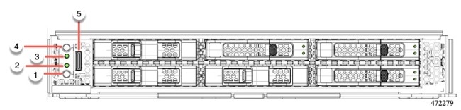
Compute Node Front Panel
The Cisco UCS X210c M7 front panel contains system LEDs that provide visual indicators for how the overall compute node is operating. An external connector is also supported.
Compute Node Front Panel
|
1 |
Power LED and Power Switch The LED provides a visual indicator about whether the compute node is on or off.
The switch is a push button that can power off or power on the compute node. See Front Panel Buttons. |
2 |
System Activity LED The LED blinks to show whether data or network traffic is written to or read from the compute node. If no traffic is detected, the LED is dark. The LED is updated every 10 seconds. |
|
3 |
System Health LED A multifunction LED that indicates the state of the compute node.
|
4 |
Locator LED/Switch The LED provides a visual indicator that glows solid blue to identify a specific compute node. The switch is a push button that toggles the Indicator LED on or off. See Front Panel Buttons. |
|
5 |
External Optical Connector (Oculink) that supports local console functionality. |
Front Panel Buttons
The front panel has some buttons that are also LEDs. See Compute Node Front Panel.
-
The front panel Power button is a multi-function button that controls system power for the compute node.
-
Immediate power up: Quickly pressing and releasing the button, but not holding it down, causes a powered down compute node to power up.
-
Immediate power down: Pressing the button and holding it down 7 seconds or longer before releasing it causes a powered-up compute node to immediately power down.
-
Graceful power down: Quickly pressing and releasing the button, but not holding it down, causes a powered-up compute node to power down in an orderly fashion.
-
-
The front panel Locator button is a toggle that controls the Locator LED. Quickly pressing the button, but not holding it down, toggles the locator LED on (when it glows a steady blue) or off (when it is dark). The LED can also be dark if the compute node is not receiving power.
For more information, see Interpreting LEDs.
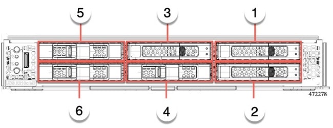
Drive Bays
Each Cisco UCS X210c M7 compute node has a front mezzanine slot that can support local storage drives of different types and quantities of 2.5-inch SAS, SATA, or NVMe drives. A drive blank panel (UCSC-BBLKD-S2) must cover all empty drive bays.
Drive bays are numbered sequentially from 1 through 6 as shown.
Drive Front Panels
The front drives are installed in the front mezzanine slot of the compute node. SAS/SATA and NVMe drives are supported.
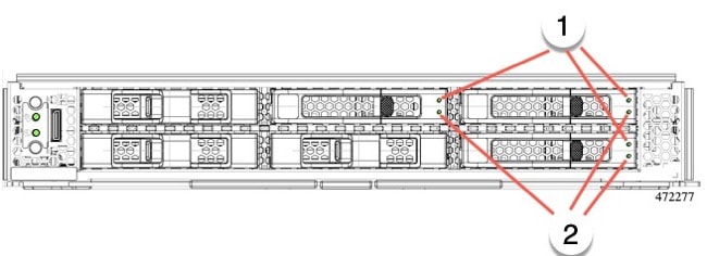
Compute Node Front Panel with SAS/SATA Drives
The compute node front panel contains the front mezzanine module, which can support a maximum of 6 SAS/SATA drives. The drives have additional LEDs that provide visual indicators about each drive's status.
|
1 |
Drive Health LED |
2 |
Drive Activity LED |
Compute Node Front Panel with NVMe Drives
The compute node front panel contains the front mezzanine module, which can support a maximum of six 2.5-inch NVMe drives.


 Feedback