Servicing a Compute Node

This chapter contains the following topics:

Removing and Installing the Compute Node Cover

The top cover for the Cisco UCS X210c M6 compute node can be removed to allow access to internal components, some of which are field-replaceable. The green button on the top cover releases the compute node, so that it can be removed from the chassis.

Removing a Compute Node Cover

To remove the cover of the UCS X210c M6 compute node, follow these steps:

Procedure


Step 1

Press and hold the button down (1, in the figure below).

Step 2

While holding the back end of the cover, slide it back, then pull it up (2).

By sliding the cover back, you enable the front edge to clear the metal lip on the rear of the front mezzanine module.


Installing a Compute Node Cover

Use this task to install a removed top cover for the UCS X210c M6 compute node.

Procedure


Step 1

Insert the cover angled so that it hits the stoppers on the base.

Step 2

Lower the compute node's cover until it reaches the bottom.

Step 3

Keeping the compute node's cover flat, slide it forward until the release button clicks.


Cover, DIMM, and CPU Installation Instructions

The following illustrations show the compute node's FRU service labels.

Figure 1. Cover Removal and Component Identification
Figure 2. DIMM, CPU, and Mini Storage Replacement Instructions

Internal Components

Figure 3. Cisco UCS X210c M6 Compute Node

1

Front mezzanine slot for NVMe or SATA drives

2

Hardware storage controller slot for front mezzanine drives

3

Front mezzanine slot connectors

4

CPU Slot 1 (populated)

5

DIMM slots (32 maximum)

6

M.2 module connector

7

CPU Slot 2 (unpopulated)

8

Motherboard USB connector

9

Trusted Platform Module (TPM) connector

10

Rear mezzanine slot, which supports X-Series mezzanine cards, such as VIC 14825.

11

Bridge Card, which connects rear mezzanine card and the mLOM

12

mLOM slot for an X-Series mLOM network adapter, such as VIC 14425.

Replacing a Drive

You can remove and install some drives without removing the compute node from the chassis. All drives have front-facing access, and they can be removed and inserted by using the ejector handles.

The SAS/SATA or NVMe drives supported in this compute node come with the drive sled attached. Spare drive sleds are not available.

Before upgrading or adding a drive to a running compute node, check the service profile in Cisco UCS Intersight and make sure the new hardware configuration will be within the parameters allowed by the service profile.


Caution


To prevent ESD damage, wear grounding wrist straps during these procedures.


NVMe SSD Requirements and Restrictions

For 2.5-inch NVMe SSDs, be aware of the following:

Enabling Hot Plug Support

Surprise and OS-informed hotplug is supported with the following conditions:

  • VMD must be enabled to support hotplug. VMD must be enabled before installing an OS on the drive.

  • If VMD is not enabled, surprise hotplug is not supported, and you must do OS-informed hotplug instead.

  • VMD is required for both surprise hotplug and drive LED support.

Removing a Drive

Use this task to remove a SAS/SATA or NVMe drive from the compute node.


Caution


Do not operate the system with an empty drive bay. If you remove a drive, you must reinsert a drive or cover the empty drive bay with a drive blank.


Procedure


Step 1

Push the release button to open the ejector, and then pull the drive from its slot.

Caution


To prevent data loss, make sure that you know the state of the system before removing a drive.

Step 2

Place the drive on an antistatic mat or antistatic foam if you are not immediately reinstalling it in another compute node.

Step 3

Install a drive blanking panel to maintain proper airflow and keep dust out of the drive bay if it will remain empty.


What to do next

Cover the empty drive bay. Choose the appropriate option:

Installing a Drive


Caution


For hot installation of drives, after the original drive is removed, you must wait for 20 seconds before installing a drive. Failure to allow this 20-second wait period causes the management software to display incorrect drive inventory information. If incorrect drive information is displayed, remove the affected drive(s), wait for 20 seconds, then reinstall them.


To install a SAS/SATA or NVMe drive in the compute node, follow this procedure:

Procedure


Step 1

Place the drive ejector into the open position by pushing the release button.

Step 2

Gently slide the drive into the empty drive bay until it seats into place.

Step 3

Push the drive ejector into the closed position.

You should feel the ejector click into place when it is in the closed position.


Basic Troubleshooting: Reseating a SAS/SATA Drive

Sometimes it is possible for a false positive UBAD error to occur on SAS/SATA HDDs installed in the server.

  • Only drives that are managed by the UCS MegaRAID controller are affected.

  • Drives can be affected regardless where they are installed in the server (front-loaded, rear-loaded, and so on).

  • Both SFF and LFF form factor drives can be affected.

  • Drives installed in all Cisco UCS X-Series servers processors can be affected.

  • Drives can be affected regardless of whether they are configured for hotplug or not.

  • The UBAD error is not always terminal, so the drive is not always defective or in need of repair or replacement. However, it is also possible that the error is terminal, and the drive will need replacement.

Before submitting the drive to the RMA process, it is a best practice to reseat the drive. If the false UBAD error exists, reseating the drive can clear it. If successful, reseating the drive reduces inconvenience, cost, and service interruption, and optimizes your server uptime.


Note


Reseat the drive only if a UBAD error occurs. Other errors are transient, and you should not attempt diagnostics and troubleshooting without the assistance of Cisco personnel. Contact Cisco TAC for assistance with other drive errors.


To reseat the drive, see Reseating a SAS/SATA Drive.

Reseating a SAS/SATA Drive

Sometimes, SAS/SATA drives can throw a false UBAD error, and reseating the drive can clear the error.

Use the following procedure to reseat the drive.


Caution


This procedure might require powering down the server. Powering down the server will cause a service interruption.


Before you begin

Before attempting this procedure, be aware of the following:

  • Before reseating the drive, it is a best practice to back up any data on it.

  • When reseating the drive, make sure to reuse the same drive bay.

    • Do not move the drive to a different slot.

    • Do not move the drive to a different server.

    • If you do not reuse the same slot, the Cisco management software (for example, Cisco IMM) might require a rescan/rediscovery of the server.

  • When reseating the drive, allow 20 seconds between removal and reinsertion.

Procedure

Step 1

Attempt a hot reseat of the affected drive(s).

For a front-loading drive, see Removing a Drive and Installing a Drive.

Step 2

During boot up, watch the drive's LEDs to verify correct operation.

See Interpreting LEDs.

Step 3

If the error persists, cold reseat the drive, which requires a server power down. Choose the appropriate option:

  1. Use your server management software to gracefully power down the server.

    See the appropriate Cisco management software documentation.

  2. If server power down through software is not available, you can power down the server by pressing the power button.

    See Front Panel Buttons.

  3. Reseat the drive as documented in Step 1.

  4. When the drive is correctly reseated, restart the server, and check the drive LEDs for correct operation as documented in Step 2.

Step 4

If hot and cold reseating the drive (if necessary) does not clear the UBAD error, choose the appropriate option:

  1. Contact Cisco Systems for assistance with troubleshooting.

  2. Begin an RMA of the errored drive.


Removing a Drive Blank

A maximum of six SAS/SATA or NVMe drives are contained in the front mezzanine storage module as part of the drive housing. The drives are front facing, so removing them does not require any disassembly.

Use this procedure to remove a drive blank from the compute node.

Procedure


Step 1

Grasp the drive blank handle.

Step 2

Slide the drive blank out of the slot.


What to do next

Cover the empty drive bay. Choose the appropriate option:

Installing a Drive Blank

Use this task to install a drive blank.

Procedure


Step 1

Align the drive blank so that the sheet metal is facing down.

Step 2

Holding the blank level, slide it into the empty drive bay.


Replacing the Front Mezzanine Module

The front mezzanine module is a steel cage that contains the compute node's storage devices or a mix of GPUs and drives. The front mezzanine storage module can contain any of the following storage configurations:

  • NVMe drives

  • SAS/SATA drives

  • Cisco T4 GPUs plus U.2 NVMe drives

In the front mezzanine slot, the server can use one of the following front storage module options:

  • A front mezzanine blank (UCSX-X10C-FMBK) for systems without local disk requirements.

  • Compute Pass Through Controller (UCSX-X10C-PT4F): supports up to six hot pluggable 15mm NVMe drives directly connected to CPU 1. RAID capability which is supported with Intel Virtual RAID on CPU (VROC).

  • MRAID Storage Controller Module (UCSX-X10C-RAIDF):

    • Supports a mixed drive configuration of up to six SAS, SATA, and NVMe (maximum of four) drives.

    • Provides HW RAID support for SAS/SATA drives in multiple RAID groups and levels.

    • NVMe drives support RAID with Intel Virtual RAID on CPU (VROC) in slots 1 to 4 with direct connections to CPU 1.

  • The front mezzanine module also contains the SuperCap module. For information about replacing the SuperCap module, see Replacing the SuperCap Module.


    Note


    The SuperCap module is only needed when the MRAID Storage Controller module (UCSX-X10C-RAIDF) is installed.


  • A compute and storage option consisting of the following:

    • A GPU adapter card supporting zero, one or two, Cisco T4 GPUs (UCSX-GPU-T4-MEZZ)

    • A storage adapter and riser card supporting zero, one, or two U.2 NVMe RAID drives

The front mezzanine module can be replaced as a whole unit, or to give easier access to some of the storage drives that it holds. SAS/SATA and the NVMe drives are accessible directly through the front of the front mezzanine panel and are hot pluggable.

To replace the front mezzanine module, use the following topics:

Front Mezzanine Module Guidelines

Be aware of the following guidelines for the front mezzanine slot:

  • For MRAID Storage Controller Module (UCSX-X10C-RAIDF), M.2 Mini Storage, and NVMe storage, UEFI boot mode is supported.

  • The compute node has a configuration option that supports up to 2 Cisco T4 GPUs (UCSX-GPU-T4-MEZZ) and up to two Cisco U.2 NVMe drives in the front mezzanine slot. This optional configuration is interchangeable with the standard configuration of all drives. For information about the GPU-based front mezzanine option, see the Cisco UCS X10c Front Mezzanine GPU Module Installation and Service Guide.

Removing the Front Mezzanine Module

Use the following procedure to remove the front mezzanine module. This procedure applies to the following modules:

  • Front mezzanine blank (UCSX-X10C-FMBK)

  • Compute Pass Through Controller (UCSX-X10C-PT4F)

  • MRAID Storage Controller Module (UCSX-X10C-RAIDF)

Before you begin

To remove the front mezzanine module, you need a T8 screwdriver and a #2 Phillips screwdriver.


Note


The compute node has a configuration option that supports up to 2 Cisco T4 GPUs (UCSX-GPU-T4-MEZZ) and up to two Cisco U.2 NVMe drives in the front mezzanine slot. This optional configuration is interchangeable with the standard configuration of all drives. For information about removing the GPU-based front mezzanine option, see the Cisco UCS X10c Front Mezzanine GPU Module Installation and Service Guide.


Procedure


Step 1

If the compute node's cover is not already removed, remove it now. Remove the compute node cover.

See Removing a Compute Node Cover.

Step 2

Remove the securing screws:

  1. Using a #2 Phillips screwdriver, loosen the two captive screws on the top of the front mezzanine module.

    Note


    This step may be skipped if removing the front mezzanine blank (UCSX-X10C-FMBK).

  2. Using a T8 screwdriver, remove the two screws on each side of the compute node that secure the front mezzanine module to the sheet metal.

Step 3

Making sure that all the screws are removed, lift the front mezzanine module to remove it from the compute node.


What to do next

To install the front mezzanine module, see Installing the Front Mezzanine Module

Installing the Front Mezzanine Module

Use the following procedure to install the front mezzanine module. This procedure applies to the following modules:

  • Front mezzanine blank (UCSX-X10C-FMBK)

  • Compute Pass Through Controller (UCSX-X10C-PT4F)

  • MRAID Storage Controller Module (UCSX-X10C-RAIDF)

Before you begin

To install the front mezzanine module, you need a T8 screwdriver and a #2 Phillips screwdriver.


Note


The compute node has a configuration option that supports up to 2 Cisco T4 GPUs (UCSX-GPU-T4-MEZZ) and up to two Cisco U.2 NVMe drives in the front mezzanine slot. This optional configuration is interchangeable with the standard configuration of all drives. For information about installing the GPU-based front mezzanine option, see the Cisco UCS X10c Front Mezzanine GPU Module Installation and Service Guide.


Procedure


Step 1

Align the front mezzanine module with its slot on the compute node.

Step 2

Lower the front mezzanine module onto the compute node, making sure that the screws and screwholes line up.

Step 3

Secure the front mezzanine module to the compute node.

  1. Using a #2 Phillips screwdriver, tighten the captive screws on the top of the front mezzanine module.

    Note


    This step may be skipped if installing the front mezzanine blank (UCSX-X10C-FMBK).

  2. Using a T8 screwdriver, insert and tighten the four screws, two on each side of the sever node.


What to do next

If you removed the drives from the front mezzanine module, reinstall them now. See Installing a Drive.

Replacing the SuperCap Module

The SuperCap module (UCSB-MRAID-SC) is a battery bank which connects to the front mezzanine storage module board and provides power to the RAID controller if facility power is interrupted. The front mezzanine with the SuperCap module installed is UCSX-X10C-RAIDF.


Note


The SuperCap module is only needed when the MRAID Storage Controller module (UCSX-C10C-RAIDF) is installed.


Note


To remove the SuperCap Module you must remove the front mezzanine module.


To replace the SuperCap module, use the following topics:

Removing the SuperCap Module

The SuperCap module is part of the Front Mezzanine Module, so the Front Mezzanine Module must be removed from the compute node to provide access to the SuperCap module.

The SuperCap module sits in a plastic tray on the underside of the front mezzanine board. The module connects to the board through a ribbon cable with one connector to the module.
Figure 4. Location of the SuperCap Module on the UCS X210c M6 Compute Node

To replace the SuperCap module, follow these steps:

Procedure


Step 1

If you have not already removed the Front Mezzanine module, do so now.

See Removing the Front Mezzanine Module.

Step 2

Before removing the SuperCap module, note its orientation in the tray as shown in the previous image.

When correctly oriented, the SuperCap connection faces downward so that it easily plugs into the socket on the board. You will need to install the new SuperCap module with the same orientation.

Step 3

Grasp the cable connector at the board and gently pull to disconnect the connector.

Step 4

Grasp the sides of the SuperCap module, but not the connector, and lift the SuperCap module out of the tray.

You might feel some resistance because the tray is curved to secure the module.

Step 5

Disconnect the ribbon cable from the SuperCap module:

  1. On the SuperCap module, locate the lever that secures the ribbon cable to the battery pack.

  2. Gently pivot the securing lever downward to release the ribbon cable connection from the SuperCap module.

Step 6

Remove the existing battery pack from its case, and insert a new one, making sure to align the new battery pack so that the connector aligns with the ribbon cable.


What to do next

Installing the SuperCap Module

Installing the SuperCap Module

If you removed the SuperCap module, use this procedure to reinstall and reconnect it.

Procedure


Step 1

Insert the Super Cap module into its case.

  1. Align the SuperCap module so that the connector will meet the connector.

  2. Before seating the SuperCap module, make sure that the ribbon cable is not in the way. You do not want to pinch the ribbon cable when you install the SuperCap.

  3. When the ribbon cables are clear of the case, press the SuperCap module until it is seated in the case.

    You might feel some resistance as the SuperCap snaps into place.

Step 2

When the SuperCap module is completely seated in its plastic case, pivot the securing lever to connect the ribbon cable to the SuperCap module.

Step 3

Align the SuperCap module with its slot on the module and seat the module into the slot.

Caution


Make sure not to pinch the ribbon cable while inserting the SuperCap module into the slot.

When the SuperCap is securely seated in the slot, the module does not rock or twist.

Step 4

After the SuperCap module is seated, reconnect the ribbon cable to the board.


Replacing CPUs and Heatsinks

This topic describes the configuration rules and procedure for replacing CPUs and heatsinks.

CPU Configuration Rules

This compute node has two CPU sockets on the motherboard. Each CPU supports 16 DIMM channels (16 DIMM slots). See Memory Population Guidelines.

  • The compute node can operate with one or two identical CPUs installed.

  • The minimum configuration is at least CPU 1 installed. Install CPUs 1 first, then CPU2.

    The following restrictions apply when using a single-CPU configuration:

    • Any unused CPU socket must have the protective dust cover from the factory installed.

    • The maximum number of DIMMs is 16. Only CPU1 channels A1 through H1 are used.

Tools Required for CPU Replacement

You need the following tools and equipment for this procedure:

  • T-30 Torx driver—Supplied with replacement CPU.

  • #1 flat-head screwdriver—Supplied with replacement CPU.

  • CPU assembly tool for M6 processors—Supplied with replacement CPU. Can be ordered separately as Cisco PID UCS-CPUATI-3.

  • Heatsink cleaning kit—Supplied with replacement CPU. Can be ordered separately for the front or rear heatsink:

    • Front heatsink kit: UCSX-C-M6-HS-F

    • Rear heatsink kit: UCSX-C-M6-HS-R

    One cleaning kit can clean up to four CPUs.

  • Thermal interface material (TIM)—Syringe supplied with replacement CPU. Use only if you are reusing your existing heatsink (new heatsinks have pre-applied TIM). Can be ordered separately as Cisco PID UCS-CPU-TIM=.

    One TIM kit covers one CPU.

Removing the CPU and Heatsink

Use the following procedure to remove an installed CPU and heatsink from the blade server. With this procedure, you will remove the CPU from the motherboard, disassemble individual components, then place the CPU and heatsink into the fixture that came with the CPU.

Procedure


Step 1

Detach the CPU and heatsink (the CPU assembly) from the CPU socket.

  1. Using the T30 Torx driver, loosen all the securing nuts in a diagonal pattern, you can start at any nut.

  2. Push the rotating wires towards each other to move them to the unlocked position.

    Caution


    Make sure that the rotating wires are as far inward as possible. When fully unlocked, the bottom of the rotating wire disengages and allows the removal of the CPU assembly. If the rotating wires are not fully in the unlocked position, you can feel resistance when attempting to remove the CPU assembly.

Step 2

Remove the CPU assembly from the motherboard.

  1. Grasp the heatsink along the edge of the fins and lift the CPU assembly off of the motherboard.

    Caution

     
    While lifting the CPU assembly, make sure not to bend the heatsink fins. Also, if you feel any resistance when lifting the CPU assembly, verify that the rotating wires are completely in the unlocked position.
  2. Put the CPU assembly on a rubberized mat or other ESD-safe work surface.

    When placing the CPU on the work surface, the heatsink label should be facing up. Do not rotate the CPU assembly upside down.

  3. Ensure that the heatsink sits level on the work surface.

Step 3

Attach a CPU dust cover (UCS-CPU-M6-CVR=) to the CPU socket.

  1. Align the posts on the CPU bolstering plate with the cutouts at the corners of the dust cover.

  2. Lower the dust cover and simultaneously press down on the edges until it snaps into place over the CPU socket.

    Caution


    Do not press down in the center of the dust cover!


Step 4

Detach the CPU from the CPU carrier by disengaging CPU clips and using the TIM breaker.

  1. Turn the CPU assembly upside down, so that the heatsink is pointing down.

    This step enables access to the CPU securing clips.

  2. Gently lift the TIM breaker (1 in the following illustration) in a 90-degree upward arc to partially disengage the CPU clips on this end of the CPU carrier.

  3. Lower the TIM breaker into the u-shaped securing clip to allow easier access to the CPU carrier.

    Note


    Make sure that the TIM breaker is completely seated in the securing clip.

  4. Gently pull up on the outer edge of the CPU carrier (2) so that you can disengage the second pair of CPU clips near both ends of the TIM breaker.

    Caution


    Be careful when flexing the CPU carrier! If you apply too much force you can damage the CPU carrier. Flex the carrier only enough to release the CPU clips. Make sure to watch the clips while performing this step so that you can see when they disengage from the CPU carrier.

  5. Gently pull up on the outer edge of the CPU carrier so that you can disengage the pair of CPU clips (3 in the following illustration) which are opposite the TIM breaker.

  6. Grasp the CPU carrier along the short edges and lift it straight up to remove it from the heatsink.

Step 5

Transfer the CPU and carrier to the fixture.

  1. When all the CPU clips are disengaged, grasp the carrier and lift it and the CPU to detach them from the heatsink.

    Note


    If the carrier and CPU do not lift off of the heatsink, attempt to disengage the CPU clips again.

  2. Flip the CPU and carrier right-side up so that the words PRESS are visible.

  3. Align the posts on the fixture and the pin 1 locations on the CPU carrier and the fixture (1 in the following illustration).

  4. Lower the CPU and CPU carrier onto the fixture.


Step 6

Use the provided cleaning kit (UCSX-HSCK) to remove all of the thermal interface barrier (thermal grease) from the CPU, CPU carrier, and heatsink.

Important


Make sure to use only the Cisco-provided cleaning kit, and make sure that no thermal grease is left on any surfaces, corners, or crevices. The CPU, CPU carrier, and heatsink must be completely clean.


What to do next

  • If you will not be installing a CPU, verify that a CPU socket cover is installed. This option is valid only for CPU socket 2 because CPU socket 1 must always be populated in a runtime deployment.

Installing the CPU and Heatsink

Use this procedure to install a CPU if you have removed one, or if you are installing a CPU in an empty CPU socket. To install the CPU, you will move the CPU to the fixture, then attach the CPU assembly to the CPU socket on the server mother board.

Procedure


Step 1

Remove the CPU socket dust cover (UCS-CPU-M6-CVR=) on the server motherboard.

  1. Push the two vertical tabs inward to disengage the dust cover.

  2. While holding the tabs in, lift the dust cover up to remove it.

  3. Store the dust cover for future use.

    Caution


    Do not leave an empty CPU socket uncovered. If a CPU socket does not contain a CPU, you must install a CPU dust cover.

Step 2

Grasp the CPU fixture on the edges labeled PRESS, lift it out of the tray, and place the CPU assembly on an ESD-safe work surface.

Step 3

Apply new TIM.

Note

 
The heatsink must have new TIM on the heatsink-to-CPU surface to ensure proper cooling and performance.
  • If you are installing a new heatsink, it is shipped with a pre-applied pad of TIM. Go to step 4.

  • If you are reusing a heatsink, you must remove the old TIM from the heatsink and then apply new TIM to the CPU surface from the supplied syringe. Continue with step a below.

  1. Apply the Bottle #1 cleaning solution that is included with the heatsink cleaning kit (UCSX-HSCK=), as well as the spare CPU package, to the old TIM on the heatsink and let it soak for a least 15 seconds.

  2. Wipe all of the TIM off the heatsink using the soft cloth that is included with the heatsink cleaning kit. Be careful to avoid scratching the heatsink surface.

  3. Completely clean the bottom surface of the heatsink using Bottle #2 to prepare the heatsink for installation.

  4. Using the syringe of TIM provided with the new CPU (UCS-CPU-TIM=), apply 1.5 cubic centimeters (1.5 ml) of thermal interface material to the top of the CPU. Use the pattern shown in the following figure to ensure even coverage.

    Figure 5. Thermal Interface Material Application Pattern

    Caution


    Use only the correct heatsink for your CPU. CPU 1 uses heatsink UCSX-HS-M6-R and CPU 2 uses heatsink UCSX-HS-M6-F.

Step 4

Attach the heatsink to the CPU fixture.

  1. Grasp the heatsink by the fins (1, in the following illustration), align pin 1 location of the heatsink with the pin 1 location on the CPU fixture (2), then lower the heatsink onto the CPU fixture.

    The heatsink is correctly oriented when the embossed triangle points to the CPU pin 1 location, as shown.

    Caution


    Make sure the rotating wires are in the unlocked position so that the feet of the wires do not impede installing the heatsink.

Step 5

Install the CPU assembly onto the CPU motherboard socket.

  1. Push the rotating wires inward to the unlocked position so that they do not obstruct installation.


  2. Grasp the heatsink by the fins (1 in the following illustration), align the pin 1 location on the heatsink with the pin 1 location on the CPU socket (2), then seat the heatsink onto the CPU socket.

    The heatsink is correctly oriented when the embossed triangle points to the CPU pin 1 location, as shown.

    Caution


    Make sure the rotating wires are in the unlocked position so that the feet of the wires do not impede installing the heatsink.

  3. Push the rotating wires away from each other to lock the CPU assembly into the CPU socket (1 in the following illustration).

    Caution


    Make sure that you close the rotating wires completely before using the Torx driver to tighten the securing nuts.

  4. Set the T30 Torx driver to 12 in-lb of torque and tighten the 4 securing nuts to secure the CPU to the motherboard (2). You can start with any nut, but make sure to tighten the securing nuts in a diagonal pattern.


Replacing Memory DIMMs

The DIMMs that this compute node supports are updated frequently. A list of supported and available DIMMs is in Cisco UCS X210c M6 Specification Sheet.

Do not use any DIMMs other than those listed in the specification sheet. Doing so may irreparably damage the compute node and result in down time.

Memory Population Guidelines

The following is a partial list of memory usage and population guidelines. For detailed information about memory usage and population, download the Cisco UCS C220/C240/B200 M6 Memory Guide.


Caution


Only Cisco memory is supported. Third-party DIMMs are not tested or supported.


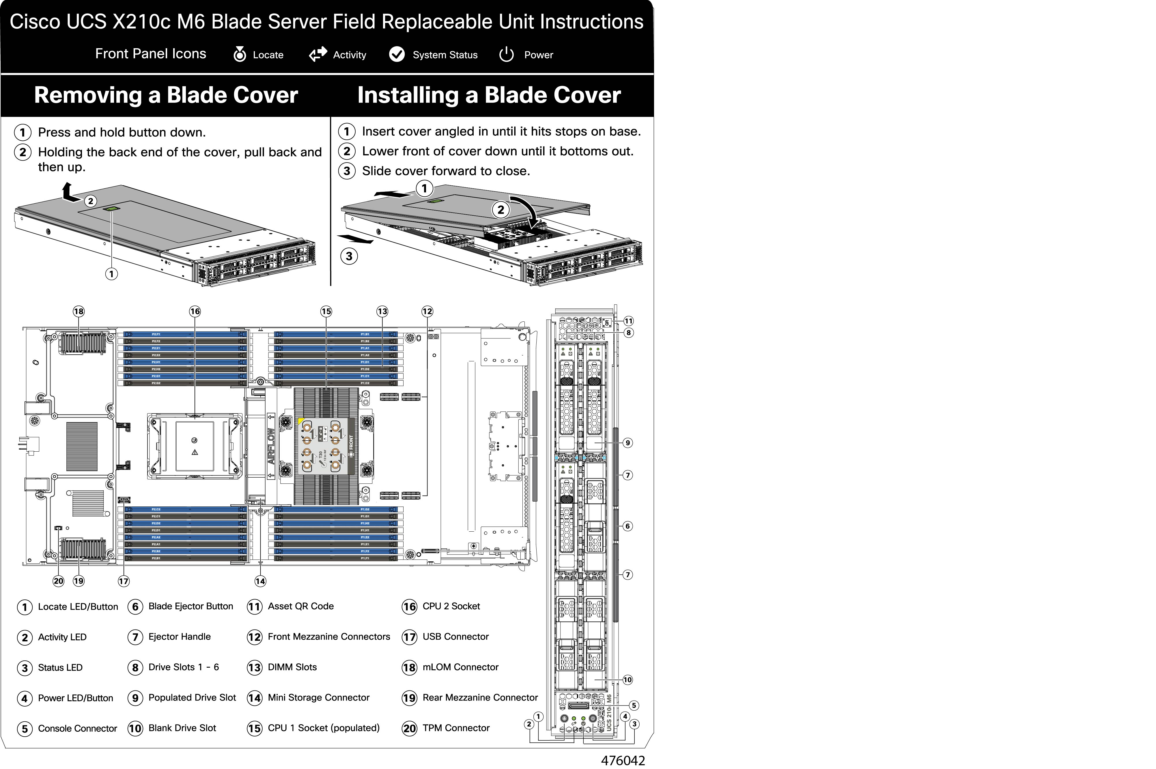
This compute node contains 32 DIMM slots—16 per CPU

Memory Considerations

  • All DIMMs must be all DDR4 DIMMs.

  • x4 DIMMs are supported.

  • DIMMs must be loaded lowest number slot first.

  • Memory ranks are 64- or 72-bit chunks of data that each memory channel for a CPU can use. Each memory channel can support a maximum of 8 memory ranks. For quad-rank DIMMs, a maximum of 2 DIMMs are supported per channel (4 ranks * 2 DIMMs).

  • Mixed ranks of DIMMs are allowed in the same channel, but you must populate higher quantity rank DIMMs in the lower numbered slots.

  • All slots must be populated with either a DIMM or a DIMM blank.

  • Validation on all permutations for 100% test coverage is not supported. See the DIMMs Population Order table for supported configurations.

  • It’s important to balance population between each CPU and each memory controller in each CPU to optimize memory capacity, except for single DIMM per CPU configurations, which should be loaded with the higher capacity DIMM on CPU1.

DIMM Identification

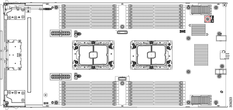
To assist with identification, each DIMM slot displays its memory processor and slot ID on the motherboard. For example, P1 A1 indicates slot A1 for processor 1.

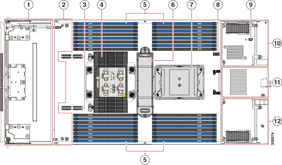
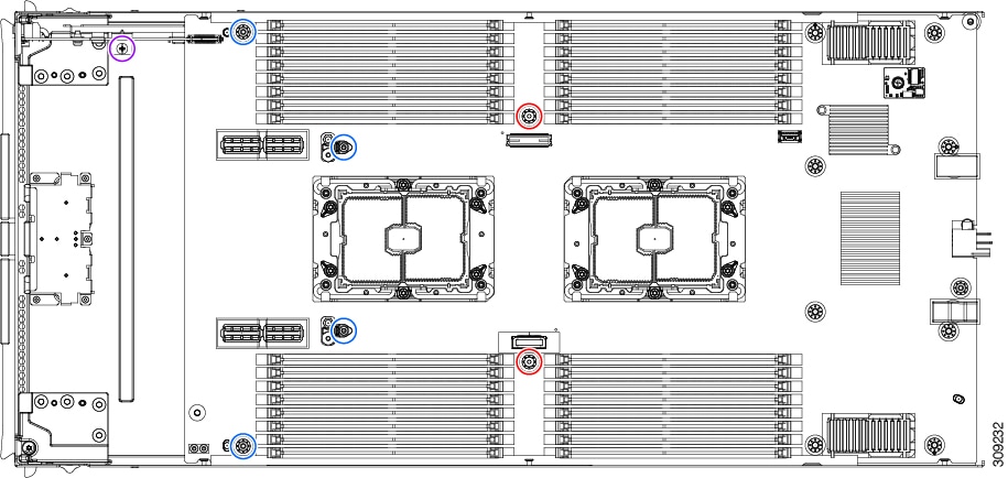
Also, you can further identify which DIMM slot connects to which CPU by dividing the blade in half vertically.

  • All DIMM slots on the left are connected to CPU 1.

  • All DIMM slots on the right are connected to CPU 2.

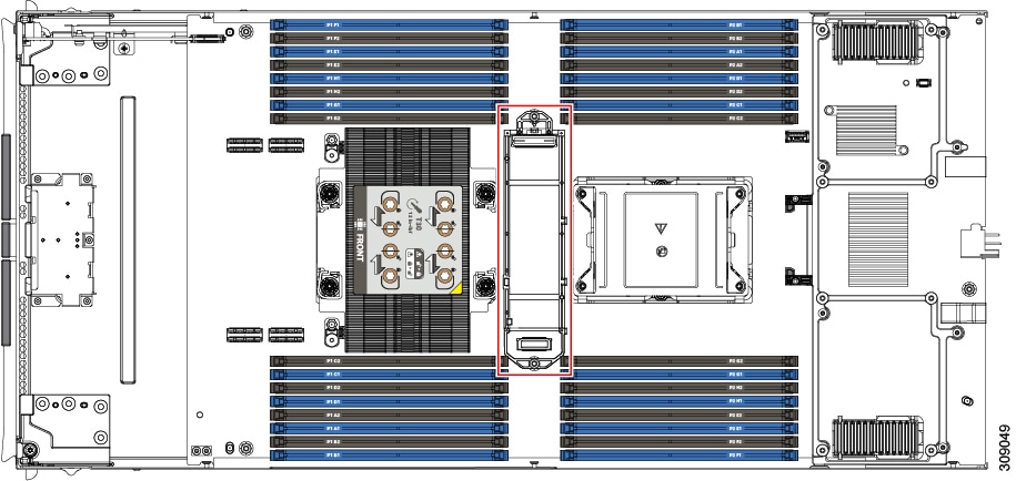
For each CPU, each set of 16 DIMMs is arranged into 8 channels, where each channel has two DIMMs. Each DIMM slot is numbered 1 or 2, and each DIMM slot 1 is blue and each DIMM slot 2 is black. Each channel is identified by two pairs of letters and numbers where the first pair indicates the processor, and the second pair indicates the memory channel and slot in the channel.

  • Channels for CPU 1 are P1 A1 and A2, P1 B1 and B2, P1 C1 and C2, P1 D1 and D2, P1 E1 and E2, P1 F1 and F2, P1 G1 and G2, P1 H1 and H2.

  • Channels for CPU 2 are P2 A1 and A2, P2 B1 and B2, P2 C1 and C2, P2 D1 and D2, P2 E1 and E2, P2 F1 and F2, P2 G1 and G2, P2 H1 and H2.

The following illustration shows the memory slot and channel IDs.

Memory Population Order

Memory slots are color coded, blue and black. The color-coded channel population order is blue slots first, then black.

For optimal performance, populate DIMMs in the order shown in the following table, depending on the number of CPUs and the number of DIMMs per CPU. If your server has two CPUs, balance DIMMs evenly across the two CPUs as shown in the table.


Note


The table below lists recommended configurations. Using 3, 5, 7, 9, 10, 11, or 13-15 DIMMs per CPU is not recommended. Other configurations results in reduced performance.


The following table shows the memory population order for DDR4 DIMMs.

Table 1. DIMMs Population Order

Number of DDR4 DIMMs per CPU (Recommended Configurations)

Populate CPU 1 Slot

Populate CPU2 Slots

P1 Blue #1 Slots

P1_slot-ID

P1 Black #2 Slots

P1_slot-ID

P2 Blue #1 Slots

P2_slot-ID

P2 Black #2 Slots

P2_slot-ID

1

A1

-

A1

-

2

A1, E1

-

A1, E1

-

4

A1, C1, E1, G1

-

A1, C1, E1, G1

-

6

A1, C1, D1, E1, G1, H1

-

A1, C1, D1, E1, G1, H1

-

8

A1, B1, C1, D1, E1, F1, G1, H1

-

A1, B1, C1, D1, E1, F1, G1, H1

-

12

A1, C1, D1, E1, G1, H1

A2, C2, D2, E2, G2, H2

A1, C1, D1, E1, G1, H1

A2, C2, D2, E2, G2, H2

16

All populated (A1 through H1)

All populated (A2 through H2)

All populated (A1 through H1)

All populated (A2 through H2)


Note


For configurations with 1, 2, 4, 6 and 8 DIMMs, install higher capacity followed by lower capacity DIMMs in alternating fashion. For example, the 4 DIMMs configuration is installed with 64GB on A1, E1 on both CPUs and 16GB on C1, G1 on both CPUs.

For configurations with 12 and 16 DIMMs, install all higher capacity DIMMs in blue slots and all lower capacity DIMMs in black slots.


DIMM Slot Keying Consideration

DIMM slots that connect to each CPU socket are oriented 180 degrees from each other. So, when you compare the DIMM slots for CPU 1 and the DIMM slots for CPU 2, the DIMMs do not install the same way. Instead, when you install DIMM attached to both CPUs, the DIMM orientation must change 180 degrees.

To facilitate installation, DIMMs are keyed to ensure correct installation. When you install a DIMM, always make sure that the key in the DIMM slot lines up with the notch in the DIMM.


Caution


If you feel resistance while seating a DIMM into its socket, do not force the DIMM or you risk damaging the DIMM or the slot. Check the keying on the slot and verify it against the keying on the bottom of the DIMM. When the slot's key and the DIMM's notch are aligned, reinstall the DIMM.


Installing a DIMM or DIMM Blank

To install a DIMM or a DIMM blank (UCS-DIMM-BLK=) into a slot on the compute node, follow these steps:

Procedure


Step 1

Open both DIMM connector latches.

Step 2

Press evenly on both ends of the DIMM until it clicks into place in its slot.

Note


Ensure that the notch in the DIMM aligns with the slot. If the notch is misaligned, it is possible to damage the DIMM, the slot, or both.

Step 3

Press the DIMM connector latches inward slightly to seat them fully.

Step 4

Populate all slots with a DIMM or DIMM blank. A slot cannot be empty.

Figure 6. Installing Memory

Memory Performance

When considering the memory configuration of the compute node, there are several things to consider. For example:

  • When mixing DIMMs of different densities (capacities), the highest density DIMM goes in slot 1 then in descending density.

  • Besides DIMM population and choice, the selected CPU(s) can have some effect on performance.

Memory Mirroring and RAS

The Intel CPUs within the compute node support memory mirroring only when 1DPC and 2DPC (8 DIMMs and 16 DIMMs per CPU) channels are populated with DIMMs. Furthermore, if memory mirroring is used, DRAM size is reduced by 50 percent for reasons of reliability.

Replacing Intel Optane Persistent Memory Modules

This topic contains information for replacing Intel Optane Data Center Persistent Memory modules (PMEMs), including population rules. PMEMs have the same form-factor as DDR4 DIMMs and they install to DIMM slots.


Note


Intel Optane persistent memory modules require Second Generation Intel Xeon Scalable processors. You must upgrade the compute node firmware and BIOS to version 4.2(x) or later and install the supported Third Generation Intel Xeon Scalable processors before installing PMEMs.


Caution


PMEMs and their sockets are fragile and must be handled with care to avoid damage during installation.


Note


To ensure the best compute node performance, it is important that you are familiar with memory performance guidelines and population rules before you install or replace PMEMs.


PMEMs can be configured to operate in one of three modes:

  • Memory Mode (default): The module operates as 100% memory module. Data is volatile and DRAM acts as a cache for PMEMs. This is the factory default mode.

  • App Direct Mode: The module operates as a solid-state disk storage device. Data is saved and is non-volatile.

Intel Optane Persistent Memory Module Population Rules and Performance Guidelines

This topic describes the rules and guidelines for maximum memory performance when using Intel Optane persistent memory modules (PMEMs) with DDR4 DIMMs.

Configuration Rules

Observe the following rules and guidelines:

  • When using PMEMs in a compute node:

    • The DDR4 DIMMs installed in the compute node must all be the same size.

    • The PMEMs installed in the compute node must all be the same size and must have the same SKU.

  • The PMEMs run at 3200 MHz.

  • Each PMEM draws 18 W sustained, with a 20 W peak.

  • For PMEMs and DIMMs population, see Cisco UCS C220/C240/ B200 M6 Memory Guide.

Installing Intel Optane Persistent Memory Modules


Note


PMEM configuration is always applied to all PMEMs in a region, including a replacement PMEM. You cannot provision a specific replacement PMEM on a preconfigured compute node.


Procedure


Step 1

Remove an existing PMEM:

  1. Decommission and power off the compute node.

  2. Remove the top cover from the compute node as described in Removing and Installing the Compute Node Cover.

  3. Slide the compute node out the front of the chassis.

    Caution


    If you are moving PMEMs with active data (persistent memory) from one compute node to another as in an RMA situation, each PMEM must be installed to the identical position in the new compute node. Note the positions of each PMEM or temporarily label them when removing them from the old compute node.

  4. Locate the PMEM that you are removing, and then open the ejector levers at each end of its DIMM slot.

Step 2

Install a new PMEM:

Note


Before installing PMEMs, see the population rules for this compute node: Intel Optane Persistent Memory Module Population Rules and Performance Guidelines.

  1. Align the new PMEM with the empty slot on the motherboard. Use the alignment feature in the DIMM slot to correctly orient the PMEM.

  2. Push down evenly on the top corners of the PMEM until it is fully seated and the ejector levers on both ends lock into place.

  3. Replace the top cover to the compute node.

  4. Replace the compute node in the chassis.

  5. Wait for Cisco Intersight to complete its automatic discovery of the compute node.

Step 3

Perform post-installation actions:

  • If the existing configuration is in 100% Memory mode, and the new PMEM is also in 100% Memory mode (the factory default), the only action is to ensure that all PMEMs are at the latest, matching firmware level.

  • If the existing configuration is fully or partly in App-Direct mode and new PMEM is also in App-Direct mode, then ensure that all PMEMs are at the latest matching firmware level and also re-provision the PMEMs by creating a new goal.

  • If the existing configuration and the new PMEM are in different modes, then ensure that all PMEMs are at the latest matching firmware level and also re-provision the PMEMs by creating a new goal.

To use the compute node's BIOS Setup Utility, see BIOS Setup Utility Menu for PMEM.


BIOS Setup Utility Menu for PMEM


Caution


Potential data loss: If you change the mode of a currently installed PMEM from App Direct or Mixed Mode to Memory Mode, any data in persistent memory is deleted.


PMEMs can be configured by using the compute node's BIOS Setup Utility or OS-related utilities. To use the BIOS Setup Utility, see the section below.

The compute node BIOS Setup Utility includes menus for PMEMs. They can be used to view or configure PMEM regions, goals, and namespaces, and to update PMEM firmware.

To open the BIOS Setup Utility, press F2 when prompted during a system boot.

The PMEM menu is on the Advanced tab of the utility:

Advanced > Intel Optane DC Persistent Memory Configuration

From this tab, you can access other menu items:

  • DIMMs: Displays the installed PMEMs. From this page, you can update PMEM firmware and configure other PMEM parameters.

    • Monitor health

    • Update firmware

    • Configure security

      You can enable security mode and set a password so that the PMEM configuration is locked. When you set a password, it applies to all installed PMEMs. Security mode is disabled by default.

    • Configure data policy

  • Regions: Displays regions and their persistent memory types. When using App Direct mode with interleaving, the number of regions is equal to the number of CPU sockets in the compute node. When using App Direct mode without interleaving, the number of regions is equal to the number of PMEMs in the compute node.

    From the Regions page, you can configure memory goals that tell the PMEM how to allocate resources.

    • Create goal config

  • Namespaces: Displays namespaces and allows you to create or delete them when persistent memory is used. Namespaces can also be created when creating goals. A namespace provisioning of persistent memory applies only to the selected region.

    Existing namespace attributes such as the size cannot be modified. You can only add or delete namespaces.

  • Total capacity: Displays the total resource allocation across the compute node.

Updating the PMEM Firmware Using the BIOS Setup Utility

You can update the PMEM firmware from the BIOS Setup Utility if you know the path to the .bin files. The firmware update is applied to all installed PMEMs.

  1. Navigate to Advanced > Intel Optane Persistent Memory Configuration > DIMMs > Update firmware

  2. Under File:, provide the file path to the .bin file.

  3. Select Update.

Servicing the mLOM

The UCS X210c M6 compute node supports a modular LOM (mLOM) card to provide additional rear-panel connectivity. The mLOM socket is on the rear corner of the motherboard.

The mLOM socket provides a Gen-3 x16 PCIe lane. The socket remains powered when the compute node is in 12 V standby power mode, and it supports the network communications services interface (NCSI) protocol.


Note


If your mLOM card is a Cisco UCS Virtual Interface Card (VIC).

To service the mLOM card, use the following procedures:

Installing an mLOM Card

Use this task to install an mLOM onto the compute node.

Before you begin

If the compute node is not already removed from the chassis, power it down and remove it now. You might need to disconnect cables to remove the compute node.

Gather a torque screwdriver.

Procedure


Step 1

Remove the top cover.

See Removing a Compute Node Cover.

Step 2

Orient the mLOM card so that the socket is facing down.

Step 3

Align the mLOM card with the motherboard socket so that the bridge connector is facing inward.

Step 4

Keeping the card level, lower it and press firmly to seat the card into the socket.

Step 5

Using a #2 Phillips torque screwdriver, tighten the captive thumbscrews to 4 in-lb of torque to secure the card.

Step 6

If your compute node has a bridge card (Cisco UCS VIC 14000 Series Bridge), reattach the bridge card.

See Installing a Bridge Card.

Step 7

Replace the top cover of the compute node.

Step 8

Reinsert the compute node into the chassis. replace cables, and then power on the compute node by pressing the Power button.


Replacing an mLOM Card

The compute node supports an mLOM in the rear mezzanine slot. Use this procedure to replace an mLOM:

Procedure


Step 1

Remove any existing mLOM card (or a blanking panel):

  1. Shut down and remove power from the compute node.

  2. Remove the compute node from the chassis. You might have to detach cables from the rear panel to provide clearance.

  3. Remove the top cover from the compute node. See Removing a Compute Node Cover.

  4. If the compute node has a UCS VIC 14000 Series Bridge, remove the thumbscrews and remove the bridge card.

  5. Loosen the captive thumbscrews that secure the mLOM card to its threaded standoffs.

  6. Lift the mLOM out of the compute node.

    You might need to gently rock the mLOM card while lifting it to disengage it from the socket.

Step 2

Install a new mLOM card:

  1. Orient the mLOM card so that the socket is facing down.

  2. Align the mLOM card with the motherboard socket.

  3. Keeping the card level, lower it and press firmly to seat the card into the socket.

  4. Tighten the captive thumbscrews to secure the card.

  5. If your compute node has a bridge card (Cisco UCS VIC 14000 Series Bridge), reattach the bridge card.

    See Installing a Bridge Card.

  6. Replace the top cover of the compute node.

  7. Reinsert the compute node into the chassis. replace cables, and then power on the compute node by pressing the Power button.


Servicing the VIC

The UCS X210c compute node supports a virtual interface card (VIC) in the rear mezzanine slot. The VIC can be either half-slot or full-slot in size.

The following VICs are supported on the compute node.

Table 2. Supported VICs on Cisco UCS X210c M6

UCSX-V4-Q25GME

UCS VIC 14825 4x25G mezz for X Compute Node

UCSX-V4-PCIME

UCS PCI Mezz card for X-Fabric Connectivity

These card are required to support connection to a UCS PCIe node.

Cisco Virtual Interface Card (VIC) Considerations

This section describes VIC card support and special considerations for this compute node.

  • A blade with only one mezzanine card is an unsupported configuration. With this configuration, blade discovery does not occur through management software such as Intersight. No error is displayed.

Installing a Rear Mezzanine Card in Addition to the mLOM VIC

The compute node has a rear mezzanine slot which can accept a virtual interface card (VIC) unless the compute node has a full size mLOM. In the case of a separate mLOM and VIC, another component (the UCS VIC 14000 Series Bridge is required to provide data connectivity between the mLOM and VIC. See Installing a Bridge Card.

Use this task to install a VIC in the rear mezzanine slot.


Note


The VIC installs upside down so that the connectors meet with the sockets on the compute node.


Before you begin

Gather a torque screwdriver.

Procedure


Step 1

Orient the VIC with the captive screws facing up and the connectors facing down.

Step 2

Align the VIC so that the captive screws line up with their threaded standoffs, and the connector for the bridge card is facing inward.

Step 3

Holding the VIC level, lower it and press firmly to seat the connectors into the sockets.

Step 4

Using a #2 Phillips torque screwdriver, tighten the captive screws to 4 in-lb of torque to secure the VIC to the compute node.


What to do next

Installing a Bridge Card

The Cisco UCS VIC 14000 Series Bridge is a physical card that provides data connection between the mLOM and VIC. Use this procedure to install the bridge card.


Note


The bridge card installs upside down so that the connectors meet with the sockets on the MLOM and VIC.


Before you begin

To install the bridge card, the compute node must have an mLOM and a VIC installed. The bridge card ties these two cards together to enable communication between them.

If these components are not already installed, install them now. See:

Procedure


Step 1

Orient the bridge card so that the Press Here to Install text is facing you.

Step 2

Align the bridge card so that the connectors line up with the sockets on the MLOM and VIC.

When the bridge card is correctly oriented, the hole in the part's sheet metal lines up with the alignment pin on the VIC.

Step 3

Keeping the bridge card level lower it onto the MLOM and VIC cards and press evenly on the part where the Press Here to Install text is.

Step 4

When the bridge card is correctly seated, use a #2 Phillips screwdriver to secure the captive screws.

Caution


Make sure the captive screws are snug, but do not overdrive them or you risk stripping the screw.


Servicing the Trusted Platform Module (TPM)

The Trusted Platform Module (TPM) is a component that can securely store artifacts used to authenticate the compute node. These artifacts can include passwords, certificates, or encryption keys. A TPM can also be used to store platform measurements that help ensure that the platform remains trustworthy. Authentication (ensuring that the platform can prove that it is what it claims to be) and attestation (a process helping to prove that a platform is trustworthy and has not been breached) are necessary steps to ensure safer computing in all environments. It is a requirement for the Intel Trusted Execution Technology (TXT) security feature, which must be enabled in the BIOS settings for a compute node equipped with a TPM.

The UCS X210c M6 Compute Node supports the Trusted Platform Module 2.0, which is FIPS140-2 compliant (UCSX-TPM3-002=).

To service the TPM, use the following tasks:

Enabling the Trusted Platform Module

Use this task to enable the TPM:

Procedure


Step 1

Install the TPM hardware.

  1. Decommission, power off, and remove the compute node from the chassis.

  2. Remove the top cover from the compute node as described in Removing and Installing the Compute Node Cover.

  3. Install the TPM to the TPM socket on the compute node motherboard and secure it using the one-way screw that is provided. See the figure below for the location of the TPM socket.

  4. Return the compute node to the chassis and allow it to be automatically reacknowledged, reassociated, and recommissioned.

  5. Continue with enabling TPM support in the compute node BIOS in the next step.

Step 2

Enable TPM Support in the BIOS.


Removing the Trusted Platform Module (TPM)

The TPM module is attached to the printed circuit board assembly (PCBA). You must disconnect the TPM module from the PCBA before recycling the PCBA. The TPM module is secured to a threaded standoff by a tamper-resistant screw. If you do not have the correct tool for the screw, you can use a pair of pliers to remove the screw.

Before you begin


Note


For Recyclers Only! This procedure is not a standard field-service option. This procedure is for recyclers who will be reclaiming the electronics for proper disposal to comply with local eco design and e-waste regulations.


To remove the Trusted Platform Module (TPM), the following requirements must be met for the compute node:

Procedure


Step 1

Locate the TPM module.

Step 2

Using the pliers, grip the head of the screw and turn it counterclockwise until the screw releases.

Step 3

Remove the TPM module and dispose of it properly.


What to do next

Remove and dispose of the PCB Assembly. See Recycling the PCB Assembly (PCBA).

Mini Storage Module

The compute node has a mini-storage module option that plugs into a motherboard socket to provide additional internal storage. The mini-storage module is an M.2 SSD module that supports up to two SATA M.2 SSDs.

Replacing an M.2 SSD Card

M.2 SSD cards are installed as a pair on the top and bottom of the M.2 module carrier.

There are some specific rules for populating mini-storage M.2 SSD cards:

  • You can use one or two M.2 SSDs in the carrier.

  • M.2 socket 1 is on the top side of the carrier; M.2 socket 2 is on the underside of the carrier (the same side as the carrier's connector to the board socket on the compute node).

  • Dual SATA M.2 SSDs can be configured in a RAID 1 array through the BIOS Setup Utility's embedded SATA RAID interface and configured through IMM.


    Note


    The M.2 SSDs are managed by the MSTOR-RAID controller.


    Note


    The embedded SATA RAID controller requires that the compute node is set to boot in UEFI mode rather than Legacy mode.


Removing an M.2 SSD

Each M.2 card plugs into a socket on the carrier. One socket is on the top of the carrier, and one socket is on the bottom.

Use the following procedure for any type of mini-storage module carrier.

Procedure

Remove the carrier from the compute node:

  1. Press out on the securing clips to disengage the module from the socket on the compute node's motherboard.

  2. Pull straight up on the storage module to remove it.


What to do next

Install the M.2 SSD.

Installing an M.2 SSD Card

The M.2 SSD plugs into a socket on the carrier. One end of the socket has two parallel guide clips to hold one end of the SSD, and the other end of the socket has two alignment pins and one retaining clip that lock the SSD into place.

Procedure

Install the M.2 SSD into the carrier.

  1. Orient the SSD correctly.

    Note


    When correctly oriented, the end of the SSD with two alignment holes lines up with the two alignment pins on the carrier.

  2. Angle the end with the screw into the end of the carrier that has 2 parallel guide clips.

  3. Press the other end of the SSD into the carrier until the alignment pins engage, and the retaining clip clicks the SSD into place.


Replacing a Boot-Optimized M.2 RAID Controller Module

The Cisco Boot-Optimized M.2 RAID Controller module connects to the mini-storage module socket on the motherboard. It includes slots for two SATA M.2 drives, plus an integrated 6-Gbps SATA RAID controller that can control the SATA M.2 drives in a RAID 1 array.

Cisco Boot-Optimized M.2 RAID Controller Considerations

Review the following considerations:

  • This controller supports RAID 1 (single volume) and JBOD mode.

  • A SATA M.2 drive in slot 1 (the top) is the first SATA device; a SATA M.2 drive in slot 2 (the underside) is the second SATA device.

    • The name of the controller in the software is MSTOR-RAID.

    • A drive in Slot 1 is mapped as drive 253; a drive in slot 2 is mapped as drive 254.

  • When using RAID, we recommend that both SATA M.2 drives are the same capacity. If different capacities are used, the smaller capacity of the two drives is used to create a volume and the rest of the drive space is unusable.

    JBOD mode supports mixed capacity SATA M.2 drives.

  • Hot-plug replacement is not supported. The compute node must be powered off.

  • Monitoring of the controller and installed SATA M.2 drives can be done using Cisco Intersight. They can also be monitored using other utilities such as UEFI HII, and Redfish.

  • The SATA M.2 drives can boot in UEFI mode only. Legacy boot mode is not supported.

  • If you replace a single SATA M.2 drive that was part of a RAID volume, rebuild of the volume is auto-initiated after the user accepts the prompt to import the configuration. If you replace both drives of a volume, you must create a RAID volume and manually reinstall any OS.

  • We recommend that you erase drive contents before creating volumes on used drives from another compute node. The configuration utility in the compute node BIOS includes a SATA secure-erase function.

  • The compute node BIOS includes a configuration utility specific to this controller that you can use to create and delete RAID volumes, view controller properties, and erase the physical drive contents. Access the utility by pressing F2 when prompted during compute node boot. Then navigate to Advanced > Cisco Boot Optimized M.2 RAID Controller.

Replacing a Cisco Boot-Optimized M.2 RAID Controller

This topic describes how to remove and replace a Cisco Boot-Optimized M.2 RAID Controller. The controller board has one M.2 socket on its top (Slot 1) and one M.2 socket on its underside (Slot 2).

Procedure

Step 1

Remove the controller from the compute node:

  1. Decommission, power off, and remove the compute node from the chassis.

  2. Remove the top cover from the compute node as described in Removing and Installing the Compute Node Cover.

  3. Press out on the securing clips to disengage the controller from the socket.

  4. Pull straight up on the controller to remove it.

Step 2

If you are transferring SATA M.2 drives from the old controller to the replacement controller, do that before installing the replacement controller:

Note


Any previously configured volume and data on the drives are preserved when the M.2 drives are transferred to the new controller. The system will boot the existing OS that is installed on the drives.

  1. Use a #1 Phillips-head screwdriver to remove the single screw that secures the M.2 drive to the carrier.

  2. Lift the M.2 drive from its socket on the carrier.

  3. Position the replacement M.2 drive over the socket on the controller board.

  4. Angle the M.2 drive downward and insert the connector-end into the socket on the carrier. The M.2 drive's label must face up.

  5. Press the M.2 drive flat against the carrier.

  6. Install the single screw that secures the end of the M.2 SSD to the carrier.

  7. Turn the controller over and install the second M.2 drive.

Figure 7. Cisco Boot-Optimized M.2 RAID Controller, Showing M.2 Drive Installation

Step 3

Install the controller to its socket on the motherboard:

  1. Position the controller over the socket, with the controller's connector facing down and at the same end as the motherboard socket. Two alignment pegs must match with two holes on the controller.

  2. Gently push down the socket end of the controller so that the two pegs go through the two holes on the carrier.

  3. Push down on the controller so that the securing clips click over it at both ends.

Step 4

Replace the top cover on the compute node.

Step 5

Return the compute node to the chassis and allow it to be automatically reacknowledged, reassociated, and recommissioned.


Recycling the PCB Assembly (PCBA)

Each compute node has a PCBA that is connected to the compute node's faceplate and sheet metal tray. You must disconnect the PCBA from the faceplate and tray to recycle the PCBA. Each compute node is attached to the sheet metal tray be the following:

  • Four M3 screws

  • Two hexagonal standoffs.

For this procedure you will need the following tools:

  • Screwdrivers: #2 Phillips, one 6mm slotted, one T8, T10, and T30.

  • Nut driver: One 6mm hex

You will need to recycle the PCBA for each compute node.

Before you begin


Note


For Recyclers Only! This procedure is not a standard field-service option. This procedure is for recyclers who will be reclaiming the electronics for proper disposal to comply with local eco design and e-waste regulations.


To remove the printed circuit board assembly (PCBA), the following requirements must be met:

Procedure


Step 1

(Optional) If the CPUs and heat sinks are still installed, remove them:

  1. Using a T30 Torx screwdriver, loosen the eight captive screws.

  2. For each CPU, push the retaining wires toward each other (inwards) to unlock the CPU and heat sink.

  3. Remove each CPU from the motherboard and flip each CPU upside down.

  4. Locate the TIM breaker and rotate it 90 degrees to break the thermal grease and disconnect the CPU from the heat sink.

    Caution


    Do not rotate the TIM breaker past 90 degrees.

Step 2

(Optional) If the front mezzanine module is installed, remove it.

  1. Use the T8 screwdriver to remove the M3 top mounting screw on each exterior side of the compute node.

  2. Use the #2 Phillips screwdriver to remove the two captive screws on the front mezzanine module.

  3. Remove the front mezzanine module.

Step 3

(Optional) If the rear bridge card is installed, use the #2 screwdriver to remove the two screws, then remove the card.

Step 4

(Optional) If the rear mezzanine card is installed, use the #2 screwdriver to remove the four captive screws, then remove the card.

Step 5

(Optional) If the mLOM card is installed, use the #2 screwdriver to remove the four captive screws, then remove the card.

Step 6

Using a T10 Torx driver, remove the two M3 screws and remove the middle M.2 module.

Step 7

Remove the compute node's rear frame.

  1. Use the T8 screwdriver to remove the M3 bottom mounting screw on each exterior side of the compute node.

  2. Turn the compute node upside down and use the T10 screwdriver to remove the two M3 mounting screws on the bottom of the sheet metal.

  3. Turn the compute node component side up and use the T10 screwdriver to remove the six M3 mounting screws at the rear of the compute node.

Step 8

If the TPM is installed, remove it.

See Removing the Trusted Platform Module (TPM).

Step 9

Disconnect the motherboard from the compute node's sheet metal.

  1. Use the 6mm hex nut driver to remove the two standoffs.

  2. Use the #2 Phillips screwdriver to remove the front mezzanine cage retaining screw, then remove the cage.

  3. Use the T10 screwdriver to remove the four M3 screws.

    Red circles ()

    6 mm standoffs (2)

    Blue circles ()

    M3 screws (4)

    Purple circle ()

    Front mezzanine cage retaining screw (1)

Step 10

Recycle the sheet metal and motherboard in compliance with your local recycling and e-waste regulations.