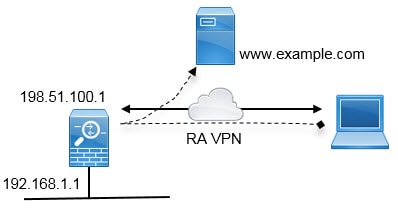
Remote Access VPN Overview
You can use the device manager to configure remote access VPN over SSL using the Secure Client sofware.
When the Secure Client negotiates an SSL VPN connection with the threat defense device, it connects using Transport Layer Security (TLS) or Datagram Transport Layer Security (DTLS). DTLS avoids latency and bandwidth problems associated with some SSL connections and improves the performance of real-time applications that are sensitive to packet delays. The client and the threat defense device negotiate the TLS/DTLS version to use. DTLS is used if the client supports it.
Maximum Concurrent VPN Sessions By Device Model
There is a maximum limit to the number of concurrent remote access VPN sessions allowed on a device based on the device model. This limit is designed so that system performance does not degrade to unacceptable levels. Use these limits for capacity planning.
|
Device Model |
Maximum Concurrent Remote Access VPN Sessions |
|---|---|
|
Firepower 1010 |
75 |
|
Firepower 1120 |
150 |
|
Firepower 1140 |
400 |
|
Secure Firewall 3110 |
3000 |
|
Secure Firewall 3120 |
6000 |
|
Secure Firewall 3130 |
15,000 |
|
Secure Firewall 3140 |
20,000 |
|
Firepower 4100 series, all models |
10,000 |
|
Firepower 9300 appliance, all models |
20,000 |
|
Threat Defense Virtual: FTDv5 |
50 |
|
Threat Defense Virtual: FTDv10, FTDv20, FTDv30 |
250 |
|
Threat Defense Virtual: FTDv50 |
750 |
|
Threat Defense Virtual: FTDv100 |
10,000 |
|
ISA 3000 |
25 |
Downloading the Secure Client Software
Before you can configure a remote access VPN, you must download the Secure Client software to your workstation. You will need to upload these packages when defining the VPN.
You should download the latest Secure Client version, to ensure that you have the latest features, bug fixes, and security patches. Regularly update the packages on the threat defense device.
 Note |
You can upload one Secure Client package per operating system: Windows, Mac, and Linux. You cannot upload multiple versions for a given OS type. |
Obtain the Secure Client software packages from software.cisco.com. You need to download the “Full Installation Package” versions of the clients.
How Users Can Install the Secure Client Software
To complete a VPN connection, your users must install the Secure Client software. You can use your existing software distribution methods to install the software directly. Or, you can have users install the Secure Client directly from the threat defense device.
Users must have Administrator rights on their workstations to install the software.
Once the Secure Client is installed, if you upload new Secure Client versions to the system, the Secure Client will detect the new version on the next VPN connection the user makes. The system will automatically prompt the user to download and install the updated client software. This automation simplifies software distribution for you and your clients.
If you decide to have users initially install the software from the threat defense device, tell users to perform the following steps.
Note |
Android and iOS users should download the Secure Client from the appropriate App Store. |
Procedure
|
Step 1 |
Using a web browser, open https://ravpn-address , where ravpn-address is the IP address or hostname of the outside interface on which you are allowing VPN connections. You identify this interface when you configure the remote access VPN. The system prompts the user to log in. If you changed the port for remote access VPN connections, users must include the custom port in the URL. For example, if you changed the port to 4443: https://ravpn.example.com:4443 |
|
Step 2 |
Log into the site. Users are authenticated using the directory server configured for the remote access VPN. Log in must be successful to continue. If log in is successful, the system determines if the user already has the required version of the Secure Client. If the Secure Client is absent from the user’s computer, or is down-level, the system automatically starts installing the Secure Client software. When installation is finished, Secure Client completes the remote access VPN connection. |
Controlling User Permissions and Attributes Using RADIUS and Group Policies
You can apply user authorization attributes (also called user entitlements or permissions) to RA VPN connections from an external RADIUS server or from a group policy defined on the threat defense device. If the threat defense device receives attributes from the external AAA server that conflict with those configured on the group policy, then attributes from the AAA server always take precedence.
The threat defense device applies attributes in the following order:
-
User attributes defined on the external AAA server—The server returns these attributes after successful user authentication or authorization.
-
Group policy configured on the threat defense device—If a RADIUS server returns the value of the RADIUS CLASS attribute IETF-Class-25 (OU= group-policy) for the user, the threat defense device places the user in the group policy of the same name and enforces any attributes in the group policy that are not returned by the server.
-
Group policy assigned by the connection profile—The connection profile has the preliminary settings for the connection, and includes a default group policy applied to the user before authentication. All users connecting to the threat defense device initially belong to this group, which provides any attributes that are missing from the user attributes returned by the AAA server, or the group policy assigned to the user.
Threat Defense devices support RADIUS attributes with vendor ID 3076. If the RADIUS server you use does not have these attributes defined, you must manually define them. To define an attribute, use the attribute name or number, type, value, and vendor code (3076).
The following topics explain the supported attributes based on whether the values are defined in the RADIUS server, or whether they are values the system sends to the RADIUS server.
Attributes Sent to the RADIUS Server
RADIUS attributes 146 and 150 are sent from the threat defense device to the RADIUS server for authentication and authorization requests. All of the following attributes are sent from the threat defense device to the RADIUS server for accounting start, interim-update, and stop requests.
|
Attribute |
Attribute Number |
Syntax, Type |
Single or Multi-valued |
Description or Value |
|---|---|---|---|---|
|
Client Type |
150 |
Integer |
Single |
The type of client that is connecting to the VPN:
|
|
Session Type |
151 |
Integer |
Single |
The type of connection:
|
|
Tunnel Group Name |
146 |
String |
Single |
The name of the connection profile that was used to establish the session, as defined on the threat defense device. The name can be 1 - 253 characters. |
Attributes Received from the RADIUS Server
The following user authorization attributes are sent to the threat defense device from the RADIUS server.
|
Attribute |
Attribute Number |
Syntax, Type |
Single or Multi-valued |
Description or Value |
|---|---|---|---|---|
|
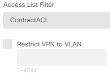
Access-List-Inbound |
86 |
String |
Single |
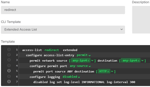
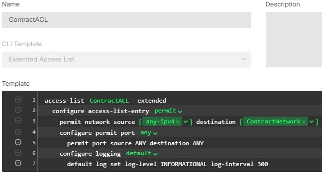
Both of the Acess-List attributes take the name of an ACL that is configured on the threat defense device. Create these ACLs using the Smart CLI Extended Access List object type (select ). These ACLs control traffic flow in the inbound (traffic entering the threat defense device) or outbound (traffic leaving the threat defense device) direction. |
|
Access-List-Outbound |
87 |
String |
Single |
|
|
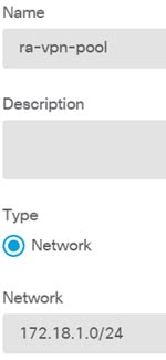
Address-Pools |
217 |
String |
Single |
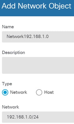
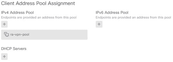
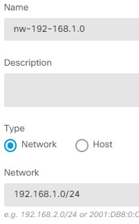
The name of a network object defined on the threat defense device that identifies a subnet, which will be used as the address pool for clients connecting to the RA VPN. Define the network object on the Objects page. |
|
Banner1 |
15 |
String |
Single |
The banner to display when the user logs in. |
|
Banner2 |
36 |
String |
Single |
The second part of the banner to display when the user logs in. Banner2 is appended to Banner1. |
|
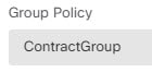
Group-Policy |
25 |
String |
Single |
The group policy to use in the connection. You must create the group policy on the RA VPN Group Policy page. You can use one of the following formats:
|
|
Simultaneous-Logins |
2 |
Integer |
Single |
The number of separate simultaneous connections the user is allowed to establish, 0 - 2147483647. |
|
VLAN |
140 |
Integer |
Single |
The VLAN on which to confine the user's connection, 0 - 4094. You must also configure this VLAN on a subinterface on the threat defense device. |
Two-Factor Authentication
You can configure two-factor authentication for the RA VPN. With two-factor authentication, the user must supply a username and static password, plus an additional item such as an RSA token or a Duo passcode. Two-factor authentication differs from using a second authentication source in that two-factor is configured on a single authentication source, with the relationship to the RSA/Duo server tied to the primary authentication source. The exception is Duo LDAP, where you configure the Duo LDAP server as the secondary authentication source.
The system has been tested with RSA tokens and Duo passcode pushed to mobile for the second factor in conjunction with any RADIUS or AD Server as the first factor in the two-factor authentication process.
RSA Two-Factor Authentication
You can configure RSA using one of the following approaches. See the RSA documentation for information about the RSA-side configuration.
-
Define the RSA Server directly in the device manager as a RADIUS server, and use the server as the primary authentication source in the RA VPN.
When using this approach, the user must authenticate using a username that is configured in the RSA RADIUS server, and concatenate the password with the one-time temporary RSA token, separating the password and token with a comma: password,token.
In this configuration, it is typical to use a separate RADIUS server (such as one supplied in Cisco ISE) to provide authorization services. You would configure the second RADIUS server as the authorization and, optionally, accounting server.
-
Integrate the RSA server with a RADIUS or AD server that supports direct integration, and configure the RA VPN to use the non-RSA RADIUS or AD server as the primary authentication source. In this case, the RADIUS/AD server uses RSA-SDI to delegate and orchestrate the two-factor authentication between the client and RSA Server.
When using this approach, the user must authenticate using a username that is configured in the non-RSA RADIUS or AD server, and concatenate the password with the one-time temporary RSA token, separating the password and token with a comma: password,token.
In this configuration, you would also use the non-RSA RADIUS server as the authorization and, optionally, accounting server.
Duo Two-Factor Authentication Using RADIUS
You can configure the Duo RADIUS server as the primary authentication source. This approach uses the Duo RADIUS Authentication Proxy.
For the detailed steps to configure Duo, please see https://duo.com/docs/cisco-firepower.
You would then configure Duo to forward authentication requests directed to the proxy server to use another RADIUS server, or an AD server, as the first authentication factor, and the Duo Cloud Service as the second factor.
When using this approach, the user must authenticate using a username that is configured on both the Duo Authentication Proxy and the associated RADIUS/AD server, and the password for the username configured in the RADIUS/AD server, followed by one of the following Duo codes:
-
Duo-passcode. For example, my-password,12345.
-
push. For example, my-password,push. Use push to tell Duo to send a push authentication to the Duo Mobile app, which the user must have already installed and registered.
-
sms. For example, my-password,sms. Use sms to tell Duo to send an SMS message with a new batch of passcodes to the user’s mobile device. The user’s authentication attempt will fail when using sms. The user must then re-authenticate and enter the new passcode as the secondary factor.
-
phone. For example, my-password,phone. Use phone to tell Duo to perform phone callback authentication.
If the username/password is authenticated, the Duo Authentication Proxy contacts the Duo Cloud Service, which validates that the request is from a valid configured proxy device and then pushes a temporary passcode to the mobile device of the user as directed. When the user accepts this passcode, the session is marked authenticated by Duo and the RA VPN is established.
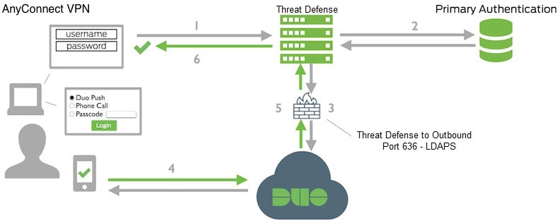
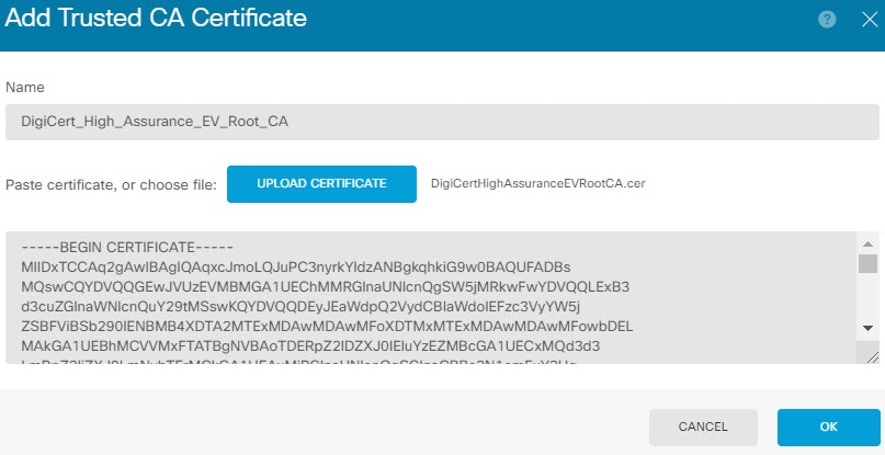
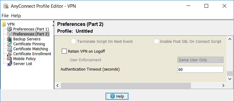
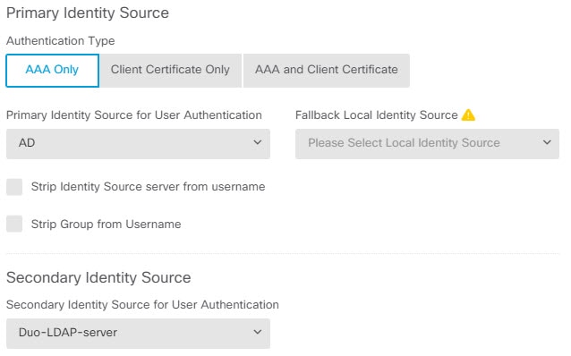
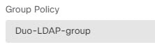
Duo Two-Factor Authentication using LDAP
You can use the Duo LDAP server as the secondary authentication source in conjunction with a Microsoft Active Directory (AD) or RADIUS server as the primary source. With Duo LDAP, the secondary authentication validates the primary authentication with a Duo passcode, push notification, or phone call.
The threat defense device communicates with Duo LDAP using LDAPS over port TCP/636.
Note that the Duo LDAP server provides authentication services only, it does not provide identity services. Thus, if you use Duo LDAP as a primary authentication source, you will not see usernames associated with RA VPN connections in any dashboards, and you will not be able to write access control rules for these users.
When using this approach, the user must authenticate using a username that is configured on both the RADIUS/AD server and the Duo LDAP server. When prompted to log in by the Secure Client, the user provides the RADIUS/AD password in the primary Password field, and for the Secondary Password, provides one of the following to authenticate with Duo. For more details, see https://guide.duo.com/anyconnect.
-
Duo passcode—Authenticate using a passcode, either generated with Duo Mobile, sent via SMS, generated by your hardware token, or provided by an administrator. For example, 1234567.
-
push—Push a login request to your phone, if you have installed and activated the Duo Mobile app. Review the request and tap Approve to log in.
-
phone—Authenticate using a phone callback.
-
sms—Request a Duo passcode in a text message. The login attempt will fail. Log in again using the new passcode.
For a detailed explanation and example of using Duo LDAP, see How to Configure Two-Factor Authentication using Duo LDAP.


 Feedback