Device Management Basics

The following topics describe how to manage devices in the Firepower System:

About Device Management

Use the Firepower Management Center to manage your devices.

About the Firepower Management Center and Device Management

When the Firepower Management Center manages a device, it sets up a two-way, SSL-encrypted communication channel between itself and the device. The Firepower Management Center uses this channel to send information to the device about how you want to analyze and manage your network traffic to the device. As the device evaluates the traffic, it generates events and sends them to the Firepower Management Center using the same channel.

By using the Firepower Management Center to manage devices, you can:

  • configure policies for all your devices from a single location, making it easier to change configurations

  • install various types of software updates on devices

  • push health policies to your managed devices and monitor their health status from the Firepower Management Center

The Firepower Management Center aggregates and correlates intrusion events, network discovery information, and device performance data, allowing you to monitor the information that your devices are reporting in relation to one another, and to assess the overall activity occurring on your network.

You can use a Firepower Management Center to manage nearly every aspect of a device’s behavior.


Note


Although a Firepower Management Center can manage devices running certain previous releases as specified in the compatibility matrix available at http://www.cisco.com/c/en/us/support/security/defense-center/products-device-support-tables-list.html, new features are not available to these previous-release devices.


What Can Be Managed by a Firepower Management Center?

You can use the Firepower Management Center as a central management point in a Firepower System deployment to manage the following devices:

  • 7000 and 8000 Series devices

  • ASA FirePOWER modules

  • NGIPSv devices

  • Firepower Threat Defense (physical hardware and virtual)

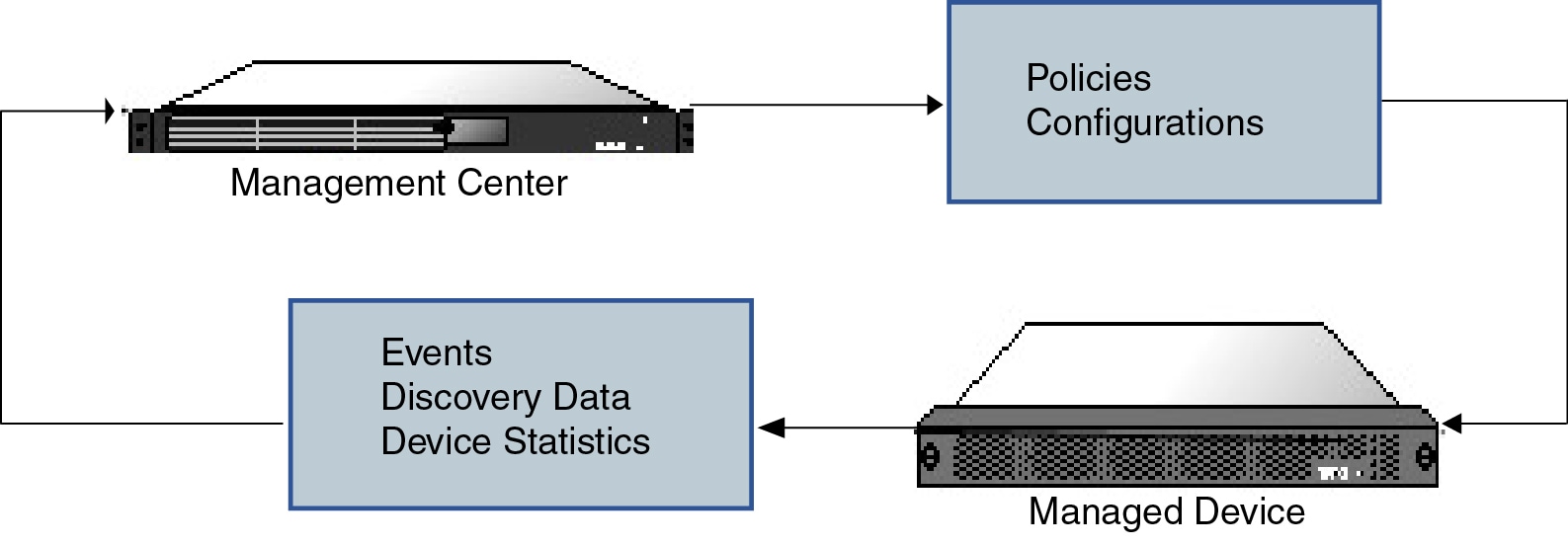
When you manage a device, information is transmitted between the Firepower Management Center and the device over a secure, SSL-encrypted TCP tunnel.

The following illustration lists what is transmitted between a Firepower Management Center and its managed devices. Note that the types of events and policies that are sent between the appliances are based on the device type.


Diagram illustrating information passed between a Firepower Management Center and its managed devices. Policy and configuration information is passed from the Firepower Management Center to the managed devices. Events, discovery data, and device statistics are passed from the managed devices to the Firepower Management Center.

Beyond Policies and Events

In addition to deploying policies to devices and receiving events from them, you can also perform other device-related tasks on the Firepower Management Center.

Backing Up a Device

You cannot create or restore backup files for NGIPSv devices or ASA FirePOWER modules.

When you perform a backup of a physical managed device from the device itself, you back up the device configuration only. To back up configuration data and, optionally, unified files, perform a backup of the device using the managing Firepower Management Center.

To back up event data, perform a backup of the managing Firepower Management Center.

Updating Devices

From time to time, Cisco releases updates to the Firepower System, including:

  • intrusion rule updates, which may contain new and updated intrusion rules

  • vulnerability database (VDB) updates

  • geolocation updates

  • software patches and updates

You can use the Firepower Management Center to install an update on the devices it manages.

About Device Management Interfaces

Each device includes a single dedicated Management interface for communicating with the FMC.

You can perform initial setup on the management interface, or on the console port.

Management interfaces are also used to communicate with the Smart Licensing server, to download updates, and to perform other management functions.

Management Interfaces on

When you set up your device, you specify the FMC IP address that you want to connect to. Both management and event traffic go to this address at initial registration. Note: In some situations, the FMC might establish the initial connection on a different management interface; subsequent connections should use the management interface with the specified IP address.

If the FMC has a separate event-only interface, the managed device sends subsequent event traffic is sent to the FMC event-only interface if the network allows. In addition, some managed-device models include an additional management interface that you can configure for event-only traffic. If the event network goes down, then event traffic reverts to the regular management interfaces on the FMC and/or on the managed device.

Management Interface Support Per Device Model

See the hardware installation guide for your model for the management interface locations.


Note


For the Firepower 4100/9300 chassis, the MGMT interface is for chassis management, not for Firepower Threat Defense logical device management. You must configure a separate NIC interface to be of type mgmt (and/or firepower-eventing), and then assign it to the Firepower Threat Defense logical device.


Note


For Firepower Threat Defense on any chassis, the physical management interface is shared between the Diagnostic logical interface, which is useful for SNMP or syslog, and is configured along with data interfaces in the FMC, and the Management logical interface for FMC communication.


See the following table for supported management interfaces on each managed device model.

Table 1. Management Interface Support on Managed Devices

Model

Management Interface

Optional Event Interface

7000 series

eth0

No support

8000 series

eth0

eth1

ASA FirePOWER services module on the ASA 5585-X

eth0

Note


eth0 is the internal name of the Management 1/0 interface.

eth1

Note


eth1 is the internal name of the Management 1/1 interface.

Firepower Threat Defense on the Firepower 4100 and 9300

management0

Note


management0 is the internal name of this interface, regardless of the physical interface ID.

management1

Note


management1 is the internal name of this interface, regardless of the physical interface ID.

Firepower Threat Defense on the ASA 5506-X, 5508-X, or 5516-X

br1

Note


br1 is the internal name of the Management 1/1 interface.

No support

Firepower Threat Defense on the 5512-X through 5555-X

br1

Note


br1 is the internal name of the Management 0/0 interface.

No support

Firepower Threat Defense Virtual

br1

No support

Network Routes on Device Management Interfaces

Management interfaces (including event-only interfaces) support only static routes to reach remote networks. When you set up your managed device, the setup process creates a default route to the gateway IP address that you specify. You cannot delete this route; you can only modify the gateway address.


Note


The routing for management interfaces is completely separate from routing that you configure for data interfaces.


The default route always uses the lowest-numbered management interface (e.g. management0).

At least one static route is recommended per management interface to access remote networks. We recommend placing each interface on a separate network to avoid potential routing problems, including routing problems from other devices to the FTD. If you do not experience problems with interfaces on the same network, then be sure to configure static routes correctly. For example, both management0 and management1 are on the same network, but the FMC management and event interfaces are on different networks. The gateway is 192.168.45.1. If you want management1 to connect to the FMC's event-only interface at 10.6.6.1/24, you can create a static route for 10.6.6.0/24 through management1 with the same gateway of 192.168.45.1. Traffic to 10.6.6.0/24 will hit this route before it hits the default route, so management1 will be used as expected.

Another example includes separate management and event-only interfaces on both the FMC and the managed device. The event-only interfaces are on a separate network from the management interfaces. In this case, add a static route through the event-only interface for traffic destined for the remote event-only network, and vice versa.

NAT Environments

Network address translation (NAT) is a method of transmitting and receiving network traffic through a router that involves reassigning the source or destination IP address. The most common use for NAT is to allow private networks to communicate with the internet. Static NAT performs a 1:1 translation, which does not pose a problem for FMC communication with devices, but port address translation (PAT) is more common. PAT lets you use a single public IP address and unique ports to access the public network; these ports are dynamically assigned as needed, so you cannot initiate a connection to a device behind a PAT router.

Normally, you need both IP addresses (along with a registration key) for both routing purposes and for authentication: the FMC specifies the device IP address when you add a device, and the device specifies the FMC IP address. However, if you only know one of the IP addresses, which is the minimum requirement for routing purposes, then you must also specify a unique NAT ID on both sides of the connection to establish trust for the initial communication and to look up the correct registration key. The FMC and device use the registration key and NAT ID (instead of IP addresses) to authenticate and authorize for initial registration.

For example, you add a device to the FMC, and you do not know the device IP address (for example, the device is behind a PAT router), so you specify only the NAT ID and the registration key on the FMC; leave the IP address blank. On the device, you specify the FMC IP address, the same NAT ID, and the same registration key. The device registers to the FMC's IP address. At this point, the FMC uses the NAT ID instead of IP address to authenticate the device.

Although the use of a NAT ID is most common for NAT environments, you might choose to use the NAT ID to simplify adding many devices to the FMC. On the FMC, specify a unique NAT ID for each device you want to add while leaving the IP address blank, and then on each device, specify both the FMC IP address and the NAT ID. Note: The NAT ID must be unique per device.

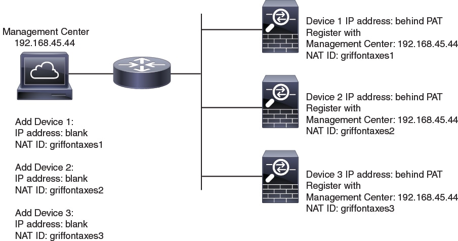
The following example shows three devices behind a PAT IP address. In this case, specify a unique NAT ID per device on both the FMC and the devices, and specify the FMC IP address on the devices.

Figure 1. NAT ID for Managed Devices Behind PAT
NAT ID for Managed Devices Behind PAT

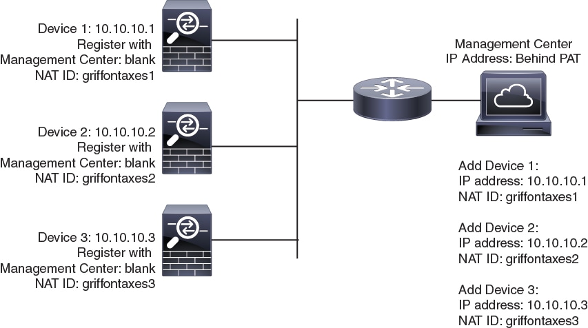
The following example shows the FMC behind a PAT IP address. In this case, specify a unique NAT ID per device on both the FMC and the devices, and specify the device IP addresses on the FMC.

Figure 2. NAT ID for FMC Behind PAT
NAT ID for FMC Behind PAT

Management and Event Traffic Channel Examples

The following example shows the Firepower Management Center and managed devices using only the default management interfaces.

Figure 3. Single Management Interface on the Firepower Management Center

The following example shows the Firepower Management Center using separate management interfaces for devices; and each managed device using 1 management interface.

Figure 4. Mutliple Management Interfaces on the Firepower Management Center

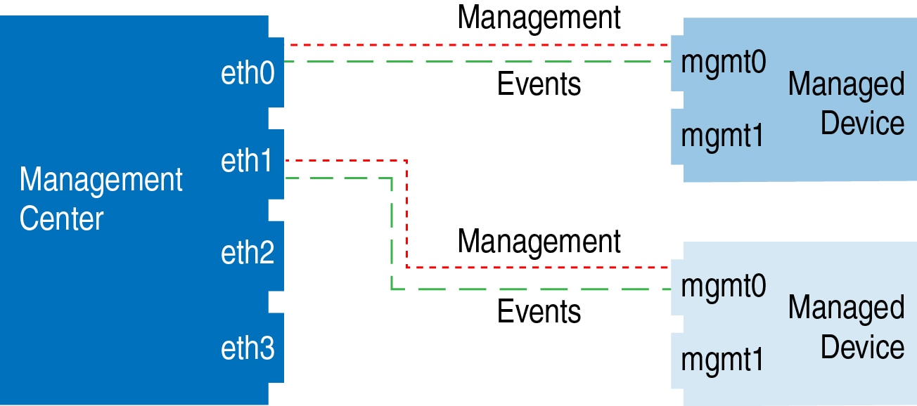
The following example shows the Firepower Management Center and managed devices using a separate event interface.

Figure 5. Separate Event Interface on the Firepower Management Center and Managed Devices

The following example shows a mix of multiple management interfaces and a separate event interface on the Firepower Management Center and a mix of managed devices using a separate event interface, or using a single management interface.

Figure 6. Mixed Management and Event Interface Usage

Requirements and Prerequisites for Device Management

Model Support

Any managed device; unless noted in the procedure.

Supported Domains

The domain in which the device resides.

User Roles

  • Admin

  • Network Admin

Complete the FTD Initial Configuration Using the CLI

Connect to the FTD CLI to perform initial setup, including setting the Management IP address, gateway, and other basic networking settings using the setup wizard. The dedicated Management interface is a special interface with its own network settings. You will also configure FMC communication settings. You can only configure the Management interface settings; you must configure data interface settings in FMC.

Before you begin

This procedure applies to all FTD devices except for the Firepower 4100/9300.

Procedure


Step 1

Connect to the FTD CLI, either from the console port or using SSH to the Management interface, which obtains an IP address from a DHCP server by default. If you intend to change the network settings, we recommend using the console port so you do not get disconnected.

Step 2

Log in with the username admin and the password Admin123.

Note


If the password was already changed, and you do not know it, you must reimage the device to reset the password to the default.

Step 3

The first time you log in to FTD, you are prompted to accept the End User License Agreement (EULA) and to change the admin password. You are then presented with the CLI setup script.

Note


You cannot repeat the CLI setup wizard unless you clear the configuration; for example, by reimaging. However, all of these settings can be changed later at the CLI using configure network commands. See the FTD command reference.

Defaults or previously entered values appear in brackets. To accept previously entered values, press Enter.

See the following guidelines:

  • Enter the IPv4 default gateway for the management interfaceThe data-interfaces setting applies only to Firepower Device Manager management; you should set a gateway IP address for Management 1/1 when using FMC. In the edge deployment example shown in the network deployment section, the inside interface acts as the management gateway. In this case, you should set the gateway IP address to be the intended inside interface IP address; you must later use FMC to set the inside IP address.

  • If your networking information has changed, you will need to reconnect—If you are connected with SSH but you change the IP address at initial setup, you will be disconnected. Reconnect with the new IP address and password. Console connections are not affected. Note also that the DHCP server on Management will be disabled if you change the IP address.

  • Manage the device locally?—Enter no to use FMC. A yes answer means you will use Firepower Device Manager instead. Note also that the DHCP server on Management 1/1 will be disabled if it wasn't already.

  • Configure firewall mode?—We recommend that you set the firewall mode at initial configuration. Changing the firewall mode after initial setup erases your running configuration.

Example:


You must accept the EULA to continue.
Press <ENTER> to display the EULA:
End User License Agreement
[...]

Please enter 'YES' or press <ENTER> to AGREE to the EULA: 

System initialization in progress.  Please stand by.
You must change the password for 'admin' to continue.
Enter new password: ********
Confirm new password: ********
You must configure the network to continue.
You must configure at least one of IPv4 or IPv6.
Do you want to configure IPv4? (y/n) [y]:
Do you want to configure IPv6? (y/n) [n]:
Configure IPv4 via DHCP or manually? (dhcp/manual) [manual]:
Enter an IPv4 address for the management interface [192.168.45.45]: 10.10.10.15
Enter an IPv4 netmask for the management interface [255.255.255.0]: 255.255.255.192
Enter the IPv4 default gateway for the management interface [data-interfaces]: 10.10.10.1
Enter a fully qualified hostname for this system [firepower]: ftd-1.cisco.com
Enter a comma-separated list of DNS servers or 'none' [208.67.222.222,208.67.220.220]:
Enter a comma-separated list of search domains or 'none' []:
If your networking information has changed, you will need to reconnect.
DHCP Server Disabled
The DHCP server has been disabled. You may re-enable with configure network ipv4 dhcp-server-enable
For HTTP Proxy configuration, run 'configure network http-proxy'

Manage the device locally? (yes/no) [yes]: no
DHCP Server Disabled
Configure firewall mode? (routed/transparent) [routed]:
Configuring firewall mode ... 

Update policy deployment information
    - add device configuration
    - add network discovery
    - add system policy

You can register the sensor to a Firepower Management Center and use the
Firepower Management Center to manage it. Note that registering the sensor
to a Firepower Management Center disables on-sensor Firepower Services
management capabilities.

When registering the sensor to a Firepower Management Center, a unique
alphanumeric registration key is always required.  In most cases, to register
a sensor to a Firepower Management Center, you must provide the hostname or
the IP address along with the registration key.
'configure manager add [hostname | ip address ] [registration key ]'

However, if the sensor and the Firepower Management Center are separated by a
NAT device, you must enter a unique NAT ID, along with the unique registration
key.
'configure manager add DONTRESOLVE [registration key ] [ NAT ID ]'

Later, using the web interface on the Firepower Management Center, you must
use the same registration key and, if necessary, the same NAT ID when you add
this sensor to the Firepower Management Center.
>

Step 4

Identify the FMC that will manage this FTD.

configure manager add {hostname | IPv4_address | IPv6_address | DONTRESOLVE} reg_key [nat_id]

  • {hostname | IPv4_address | IPv6_address | DONTRESOLVE}—Specifies either the FQDN or IP address of the FMC. If the FMC is not directly addressable, use DONTRESOLVE and also specify the nat_id. At least one of the devices, either the FMC or the FTD, must have a reachable IP address to establish the two-way, SSL-encrypted communication channel between the two devices. If you specify DONTRESOLVE in this command, then the FTD must have a reachable IP address or hostname.

  • reg_key—Specifies a one-time registration key of your choice that you will also specify on the FMC when you register the FTD. The registration key must not exceed 37 characters. Valid characters include alphanumerical characters (A–Z, a–z, 0–9) and the hyphen (-).

  • nat_id—Specifies a unique, one-time string of your choice that you will also specify on the FMC when you register the FTD when one side does not specify a reachable IP address or hostname. It is required if you set the FMC to DONTRESOLVE. The NAT ID must not exceed 37 characters. Valid characters include alphanumerical characters (A–Z, a–z, 0–9) and the hyphen (-). This ID cannot be used for any other devices registering to the FMC.

Example:


> configure manager add MC.example.com 123456
Manager successfully configured.

If the FMC is behind a NAT device, enter a unique NAT ID along with the registration key, and specify DONTRESOLVE instead of the hostname, for example:

Example:


> configure manager add DONTRESOLVE regk3y78 natid90
Manager successfully configured.

If the FTD is behind a NAT device, enter a unique NAT ID along with the FMC IP address or hostname, for example:

Example:


> configure manager add 10.70.45.5 regk3y78 natid56
Manager successfully configured.

What to do next

Register your device to a FMC.

Add a Device to the FMC

Use this procedure to add a single device to the FMC. If you plan to link devices for redundancy or performance, you must still use this procedure, keeping in mind the following points:

  • 8000 Series stacks—Use this procedure to add each device to the Firepower Management Center, then establish the stack; see Establishing Device Stacks.

  • 7000 and 8000 Series high availability—Use this procedure to add each device to the Firepower Management Center, then establish high availability; see Establishing Firepower 7000/8000 Series High Availability. For high availability stacks, first stack the devices, then establish high availability between the stacks.

  • Firepower Threat Defense high availability—Use this procedure to add each device to the Firepower Management Center, then establish high availability; see Add a Firepower Threat Defense High Availability Pair.

  • Firepower Threat Defense clusters—Make sure cluster units are in a successfully formed cluster on FXOS, then use this procedure to add each unit to the Firepower Management Center as a separate managed device. Finally, cluster the units on the Firepower Management Center. For more information, see FMC: Add a Cluster.


Note


If you have established or will establish FMC high availability, add devices only to the active (or intended active) FMC. When you establish high availability, devices registered to the active FMC are automatically registered to the standby.


Before you begin

  • Set up the device to be managed by the FMC. See:

  • If you are adding an FTD device, the FMC must be registered for Smart Licensing. A valid evaluation license is sufficient, but if it expires, you will not be able to add new devices until you successfully register.

  • If you registered a FMC and a device using IPv4 and want to convert them to IPv6, you must delete and reregister the device.

Procedure


Step 1

Choose Devices > Device Management.

Step 2

From the Add drop-down menu, choose Device.

Step 3

In the Host field, enter the IP address or the hostname of the device you want to add.

The hostname of the device is the fully qualified domain name or the name that resolves through the local DNS to a valid IP address. Use a hostname rather than an IP address if your network uses DHCP to assign IP addresses.

In a NAT environment, you may not need to specify the IP address or hostname of the device, if you already specified the IP address or hostname of the FMC when you configured the device to be managed by the FMC. For more information, see NAT Environments.

Step 4

In the Display Name field, enter a name for the device as you want it to display in the FMC.

Step 5

In the Registration Key field, enter the same registration key that you used when you configured the device to be managed by the FMC. The registration key is a one-time-use shared secret. The key can include alphanumeric characters and hyphens (-).

Step 6

In a multidomain deployment, regardless of your current domain, assign the device to a leaf Domain.

If your current domain is a leaf domain, the device is automatically added to the current domain. If your current domain is not a leaf domain, post-registration, you must switch to the leaf domain to configure the device.

Step 7

(Optional) Add the device to a device Group.

Step 8

Choose an initial Access Control Policy to deploy to the device upon registration, or create a new policy.

If the device is incompatible with the policy you choose, deploying will fail. This incompatibility could occur for multiple reasons, including licensing mismatches, model restrictions, passive vs inline issues, and other misconfigurations. After you resolve the issue that caused the failure, manually deploy configurations to the device.

Step 9

Choose licenses to apply to the device.

If you registered the FMC to use Smart Licensing, then this dialog box only shows available Smart Licenses.

Smart Licensing

Assign the Smart Licenses you need for the features you want to deploy:

  • Malware (if you intend to use AMP malware inspection)

  • Threat (if you intend to use intrusion prevention)

  • URL (if you intend to implement category-based URL filtering)

Note


You can apply an AnyConnect remote access VPN license after you add the device, from the System > Licenses > Smart Licenses page.

Classic Licensing

If you registered the FMC to use Smart Licensing, then this dialog box only shows available Smart Licenses. For classic licenses, go to the Devices > Device Management > Device > License area to assign licenses.

  • Control, Malware, and URL Filtering licenses require a Protection license.

  • VPN licenses require a 7000 or 8000 Series device.

  • Control licenses are supported on NGIPSv andASA FirePOWER devices, but do not allow you to configure 8000 Series fastpath rules, switching, routing, stacking, or device high availability.

Step 10

If you used a NAT ID during device setup, expand in the Advanced section and enter the same NAT ID in the Unique NAT ID field. The NAT ID can include alphanumeric characters and hyphens (-).

Step 11

Check the Transfer Packets check box to allow the device to transfer packets to the Firepower Management Center.

This option is enabled by default. When events like IPS or Snort are triggered with this option enabled, the device sends event metadata information and packet data to the FMC for inspection. If you disable it, only event information will be sent to the FMC but packet data is not sent.

Step 12

Click Register.

It may take up to two minutes for the FMC to verify the device’s heartbeat and establish communication. If the registration succeeds, the device is added to the list. If it fails, you will see an error message. If the device fails to register, check the following items:

  • Ping—Access the device CLI, and ping the FMC IP address using the following command:

    ping system ip_address

    If the ping is not successful, check your network settings using the show network command. If you need to change the device IP address, use the configure network {ipv4 | ipv6} manual command.

  • Registration key, NAT ID, and FMC IP address—Make sure you are using the same registration key, and if used, NAT ID, on both devices. You can set the registration key and NAT ID on the device using the configure manager add command.

For more troubleshooting information, see https://cisco.com/go/fmc-reg-error.


Delete a Device from the FMC

If you no longer want to manage a device, you can delete it from the FMC. Deleting a device:

  • Severs all communication between the FMC and the device.

  • Removes the device from the Device Management page.

  • Returns the device to local time management if the device is configured using the platform settings policy to receive time from the FMC using NTP.

After deleting the device from the FMC:

  • The FTD continues to process the traffic after you delete it from the FMC.

    • Policies, such as NAT and VPN, ACLs, and the interface configurations remain intact.

  • Registering the FTD again to the same or a different FMC, the FTD configuration is removed from the FTD.

    • The ACLs that are selected during registration replace the earlier ACLs and the interface configuration remains intact.

  • To manage the device later, re-add it to the FMC.


Note


When a device is deleted and then re-added, the FMC web interface prompts you to re-apply your access control policies. However, there is no option to re-apply the NAT and VPN policies during registration. Any previously applied NAT or VPN configuration will be removed during registration and must be re-applied after registration is complete.

Procedure


Step 1

Choose Devices > Device Management.

Step 2

Next to the device you want to delete, click Delete (delete icon).

Step 3

Confirm that you want to delete the device.


Add a Device Group

The Firepower Management Center allows you to group devices so you can easily deploy policies and install updates on multiple devices. You can expand and collapse the list of devices in the group.

In a multidomain deployment, you can create device groups within a leaf domain only. When you configure a Firepower Management Center for multitenancy, existing device groups are removed; you can re-add them at the leaf domain level.

If you add the primary device in a stack or a high-availability pair to a group, both devices are added to the group. If you unstack the devices or break the high-availability pair, both devices remain in that group.

Procedure


Step 1

Choose Devices > Device Management.

Step 2

From the Add drop-down menu, choose Add Group.

To edit an existing group, click Edit (edit icon) for the group you want to edit.

Step 3

Enter a Name.

Step 4

Under Available Devices, choose one or more devices to add to the device group. Use Ctrl or Shift while clicking to choose multiple devices.

Step 5

Click Add to include the devices you chose in the device group.

Step 6

Optionally, to remove a device from the device group, click Delete (delete icon) next to the device you want to remove.

Step 7

Click OK to add the device group.


Configure Device Settings

After you add a device, you can configure some settings on the device's Device page.

Managing System Shut Down

Smart License

Classic License

Supported Devices

Supported Domains

Access

Any

Any

Any except ASA FirePOWER

Leaf only

Admin/Network Admin


Note


You cannot shut down or restart the ASA FirePOWER with the Firepower System user interface. See the ASA documentation for more information on how to shut down the respective devices.


Procedure


Step 1

Choose Devices > Device Management.

Step 2

Next to the device that you want to restart, click Edit (edit icon).

In a multidomain deployment, if you are not in a leaf domain, the system prompts you to switch.

Step 3

Click Device.

Tip


For stacked devices, you shut down or restart an individual device on the Devices page of the appliance editor.

Step 4

To shut down the device, click Shut Down Device (shut down device icon) in the System section.

Step 5

When prompted, confirm that you want to shut down the device.

Step 6

To restart the device, click Restart Device (restart device icon).

Step 7

When prompted, confirm that you want to restart the device.


Edit Management Settings

You can edit management settings in the Management area.

Update the Hostname or IP Address in FMC

If you edit the hostname or IP address of a device after you added it to the FMC (using the device’s CLI, for example), you need to use the procedure below to manually update the hostname or IP address on the managing FMC.

Procedure

Step 1

Choose Devices > Device Management.

Step 2

Next to the device where you want to modify management options, click Edit (edit icon).

In a multidomain deployment, if you are not in a leaf domain, the system prompts you to switch.

Step 3

Click Device, and view the Management area.

Tip


For stacked devices, you modify management options on an individual device on the Device page of the appliance editor.

Step 4

Disable management temporarily by clicking the slider so it is disabled (slider disabled).

You are prompted to proceed with disabling management; click Yes.

Disabling management blocks the connection between the Firepower Management Center and the device, but does not delete the device from the Firepower Management Center.

Step 5

Edit the Host IP address or hostname by clicking Edit (edit icon).

Step 6

In the Management dialog box, modify the name or IP address in the Host field, and click Save.

Step 7

Reenable management by clicking the slider so it is enabled (slider enabled).


Modify Management Interfaces at the CLI

Modify the management interface settings on the managed device using the CLI. Many of these settings are ones that you set when you performed the initial setup; this procedure lets you change those settings, and set additional settings such as enabling an event interface if your model supports it, or adding static routes.

For information about the Firepower Threat Defense CLI, see the FTD command reference.

For information about the classic device CLI, see Classic Device Command Line Reference in this guide.

The Firepower Threat Defense and classic devices use the same commands for management interface configuration. Other commands may differ between the platforms.


Note


When using SSH, be careful when making changes to the management interface; if you cannot re-connect because of a configuration error, you will need to access the device console port.


Note


If you change the device management IP address, then see the following tasks for FMC connectivity depending on how you identified the FMC during initial device setup using the configure manager add command (see Identify a New FMC):

  • IP addressNo action. If you identified the FMC using a reachable IP address, then the management connection will be reestablished automatically after several minutes. We recommend that you also change the device IP address shown in FMC to keep the information in sync; see Update the Hostname or IP Address in FMC. This action can help the connection reestablish faster. Note: If you specified an unreachable FMC IP address, then see the procedure for NAT ID below.

  • NAT ID onlyManually reestablish the connection. If you identified the FMC using only the NAT ID, then the connection cannot be automatically reestablished. In this case, change the device management IP address in FMC according to Update the Hostname or IP Address in FMC.


Before you begin
  • For Firepower Threat Defense devices, you can create user accounts that can log into the CLI using the configure user add command.

  • For the 7000 & 8000 Series devices, you can create user accounts at the web interface as described in Creating a User Account.

Procedure

Step 1

Connect to the device CLI, either from the console port or using SSH.

Step 2

Log in with the Admin username and password.

Step 3

Enable an event-only interface (for supported models; see Management Interface Support Per Device Model).

configure network management-interface enable management_interface

configure network management-interface disable-management-channel management_interface

Example:

This example is for a Firepower 4100 or 9300 device; valid interface names differ by device type.


> configure network management-interface enable management1
Configuration updated successfully

> configure network management-interface disable-management-channel management1
Configuration updated successfully

>

The Firepower Management Center event-only interface cannot accept management channel traffic, so you should simply disable the management channel on the device event interface.

You can optionally disable events for the management interface using the configure network management-interface disable-events-channel command. In either case, the device will try to send events on the event-only interface, and if that interface is down, it will send events on the management interface even if you disable the event channel.

You cannot disable both event and management channels on an interface.

Step 4

Configure the network settings of the management interface and/or event interface:

If you do not specify the management_interface argument, then you change the network settings for the default management interface. When configuring an event interface, be sure to specify the management_interface argument. The event interface can be on a separate network from the management interface, or on the same network. If you are connected to the interface you are configuring, you will be disconnected. You can re-connect to the new IP address.

  1. Configure the IPv4 address:

    • Manual configuration:

      configure network ipv4 manual ip_address netmask gateway_ip [management_interface]

      Note that the gateway_ip in this command is used to create the default route for the device. If you configure an event-only interface, then you must enter the gateway_ip as part of the command; however, this entry just configures the default route to the value you specify and does not create a separate static route for the eventing interface. If you are using an event-only interface on a different network from the management interface, we recommend that you set the gateway_ip for use with the management interface, and then create a static route separately for the event-only interface using the configure network static-routes command.

      Example:

      
      > configure network ipv4 manual 10.10.10.45 255.255.255.0 10.10.10.1 management1
      Setting IPv4 network configuration.
      Network settings changed.
      
      >
      
      
    • DHCP (supported on the default management interface only):

      configure network ipv4 dhcp

  2. Configure the IPv6 address:

    • Stateless autoconfiguration:

      configure network ipv6 router [management_interface]

      Example:

      
      > configure network ipv6 router management0
      Setting IPv6 network configuration.
      Network settings changed.
      
      >
      
      
    • Manual configuration:

      configure network ipv6 manual ip6_address ip6_prefix_length [ip6_gateway_ip] [management_interface]

      Note that the ipv6_gateway_ip in this command is used to create the default route for the device. If you configure an event-only interface, then you must enter the ipv6_gateway_ip as part of the command; however, this entry just configures the default route to the value you specify and does not create a separate static route for the eventing interface. If you are using an event-only interface on a different network from the management interface, we recommend that you set the ipv6_gateway_ip for use with the management interface, and then create a static route separately for the event-only interface using the configure network static-routes command.

      Example:

      
      > configure network ipv6 manual 2001:0DB8:BA98::3210 64 management1
      Setting IPv6 network configuration.
      Network settings changed.
      
      >
      
      
    • DHCPv6 (supported on the default management interface only):

      configure network ipv6 dhcp

Step 5

Add a static route for the event-only interface if the Firepower Management Center is on a remote network; otherwise, all traffic will match the default route through the management interface.

configure network static-routes {ipv4 | ipv6}add management_interface destination_ip netmask_or_prefix gateway_ip

For the default route, do not use this command; you can only change the default route gateway IP address when you use the configure network ipv4 or ipv6 commands (see step 4).

For information about routing, see Network Routes on Device Management Interfaces.

Example:

> configure network static-routes ipv4 add management1 192.168.6.0 255.255.255.0 10.10.10.1
Configuration updated successfully

> configure network static-routes ipv6 add management1 2001:0DB8:AA89::5110 64 2001:0DB8:BA98::3211
Configuration updated successfully

>

To display static routes, enter show network-static-routes (the default route is not shown):


> show network-static-routes
---------------[ IPv4 Static Routes ]---------------
Interface                 : management1
Destination               : 192.168.6.0
Gateway                   : 10.10.10.1
Netmask                   : 255.255.255.0
[…]

Step 6

Set the hostname:

configure network hostname name

Example:

> configure network hostname farscape1.cisco.com

Syslog messages do not reflect a new hostname until after a reboot.

Step 7

Set the search domains:

configure network dns searchdomains domain_list

Example:

> configure network dns searchdomains example.com,cisco.com

Set the search domain(s) for the device, separated by commas. These domains are added to hostnames when you do not specify a fully-qualified domain name in a command, for example, ping system . The domains are used only on the management interface, or for commands that go through the management interface.

Step 8

Set up to 3 DNS servers, separated by commas:

configure network dns servers dns_ip_list

Example:

> configure network dns servers 10.10.6.5,10.20.89.2,10.80.54.3

Step 9

Set the remote management port for communication with the FMC:

configure network management-interface tcpport number

Example:

> configure network management-interface tcpport 8555

The FMC and managed devices communicate using a two-way, SSL-encrypted communication channel, which by default is on port 8305.

Note


Cisco strongly recommends that you keep the default settings for the remote management port, but if the management port conflicts with other communications on your network, you can choose a different port. If you change the management port, you must change it for all devices in your deployment that need to communicate with each other.

Step 10

Configure an HTTP proxy. The device is configured to directly-connect to the internet on ports TCP/443 (HTTPS) and TCP/80 (HTTP). You can use a proxy server, to which you can authenticate via HTTP Digest. After issuing the command, you are prompted for the HTTP proxy address and port, whether proxy authentication is required, and if it is required, the proxy username, proxy password, and confirmation of the proxy password.

configure network http-proxy

Example:

> configure network http-proxy
Manual proxy configuration
Enter HTTP Proxy address: 10.100.10.10
Enter HTTP Proxy Port: 80
Use Proxy Authentication? (y/n) [n]: Y
Enter Proxy Username: proxyuser
Enter Proxy Password: proxypassword
Confirm Proxy Password: proxypassword

Step 11

If you change the device management IP address, then see the following tasks for FMC connectivity depending on how you identified the FMC during initial device setup using the configure manager add command (see Identify a New FMC):

  • IP addressNo action. If you identified the FMC using a reachable IP address, then the management connection will be reestablished automatically after several minutes. We recommend that you also change the device IP address shown in FMC to keep the information in sync; see Update the Hostname or IP Address in FMC. This action can help the connection reestablish faster. Note: If you specified an unreachable FMC IP address, then you must manually reestablish the connection using Update the Hostname or IP Address in FMC.

  • NAT ID onlyManually reestablish the connection. If you identified the FMC using only the NAT ID, then the connection cannot be automatically reestablished. In this case, change the device management IP address in FMC according to Update the Hostname or IP Address in FMC.


Edit General Settings

Procedure


Step 1

Choose Devices > Device Management

Step 2

Next to the device you want to modify, click Edit (edit icon)

In a multidomain deployment, if you are not in a leaf domain, the system prompts you to switch.

Step 3

Click Device

Step 4

In the General section, click Edit (edit icon)

Step 5

Enter a Name for the managed device. 

Tip


For stacked devices, you edit the assigned device name for the stack on the Stack page of the appliance editor. You can edit the assigned device name for an individual device on the Devices page of the appliance editor. 

Step 6

Change the Transfer Packets setting: 

  • Check the check box to allow packet data to be stored with events on the Firepower Management Center
  • Clear the check box to prevent the managed device from sending packet data with the events. 

Step 7

Click Force Deploy to force deployment of current policies and device configuration to the device. 

Step 8

Click Deploy


What to do next

Edit License Settings

You can enable licenses on your device if you have available licenses on your Firepower Management Center.

Procedure


Step 1

Choose Devices > Device Management.

Step 2

Next to the device where you want to enable or disable licenses, click Edit (edit icon).

In a multidomain deployment, if you are not in a leaf domain, the system prompts you to switch.

Step 3

Click Device.

Tip


For stacked devices, you enable or disable the licenses for the stack on the Stack page of the appliance editor.

Step 4

In the License section, click Edit (edit icon).

Step 5

Check or clear the check box next to the license you want to enable or disable for the managed device.

Step 6

Click Save.


What to do next

Edit Advanced Settings

The following topics explain how to edit the advanced device settings.


Note


For information about the Transfer Packets setting, see Edit General Settings.


Configure Automatic Application Bypass

Automatic Application Bypass (AAB) allows packets to bypass detection if Snort is down or if a packet takes too long to process. AAB causes Snort to restart within ten minutes of the failure, and generates troubleshooting data that can be analyzed to investigate the cause of the Snort failure.


Caution


AAB activation partially restarts the Snort process, which temporarily interrupts the inspection of a few packets. Whether traffic drops during this interruption or passes without further inspection depends on how the target device handles traffic. See Snort® Restart Traffic Behavior for more information.


AAB limits the time allowed to process packets through an interface. You balance packet processing delays with your network’s tolerance for packet latency.

The feature functions with any deployment; however, it is most valuable in inline deployments.

Typically, you use Rule Latency Thresholding in the intrusion policy to fast-path packets after the latency threshold value is exceeded. Rule Latency Thresholding does not shut down the engine or generate troubleshooting data.

If detection is bypassed, the device generates a health monitoring alert.

By default the AAB is disabled; to enable AAB follow the steps described.

Before you begin

Model SupportASA FirePOWER, 7000 & 8000 Series, and NGIPSv

Procedure

Step 1

Choose Devices > Device Management.

Step 2

Next to the device where you want to edit advanced device settings, click Edit (edit icon).

In a multidomain deployment, if you are not in a leaf domain, the system prompts you to switch.

Step 3

Click Device (or Stack for stacked devices), then click Edit (edit icon) in the Advanced section.

Step 4

Check Automatic Application Bypass.

Step 5

Enter a Bypass Threshold from 250 ms to 60,000 ms. The default setting is 3000 milliseconds (ms).

Step 6

Click Save.


What to do next

Inspect Local Router Traffic

If locally-bound traffic matches a Monitor rule in a Layer 3 deployment, that traffic may bypass inspection. To ensure inspection of the traffic, enable Inspect Local Router Traffic.

Before you begin

Model Support7000 & 8000 Series

Procedure

Step 1

Choose Devices > Device Management.

Step 2

Next to the device where you want to edit advanced device settings, click Edit (edit icon).

In a multidomain deployment, if you are not in a leaf domain, the system prompts you to switch.

Step 3

Click Device (or Stack for stacked devices), then click Edit (edit icon) in the Advanced Settings section.

Step 4

Check Inspect Local Router Traffic to inspect exception traffic when a 7000 or 8000 Series device is deployed as a router.

Step 5

Click Save.


What to do next

Configure Fastpath Rules (8000 Series)

As a form of early traffic handling, 8000 Series fastpath rules can send traffic directly through an 8000 Series device without further inspection or logging. (In a passive deployment, 8000 Series fastpath rules simply stop analysis.) Each 8000 Series fastpath rule applies to a specific security zone or inline interface set. Because 8000 Series fastpath rules function at the hardware level, you can use only the following simple, outer-header criteria to fastpath traffic:

  • Initiator and responder IP address or address block

  • Protocol, and for TCP and UDP, initiator and responder port

  • VLAN ID

By default, 8000 Series fastpath rules affect connections from specified initiators to specified responders. To fastpath all connections that meets the rule's criteria, regardless of which host is the initiator and which is the responder, you can make the rule bidirectional.


Note


Although they perform a similar function, 8000 Series fastpath rules are not related to the Fastpath tunnel or prefilter rules that you configure in prefilter policies.

Note


When you specify a port other than Any for TCP or UDP traffic, only the first fragment in matching fragmented traffic is fastpathed. All other fragments are forwarded for further inspection. This is because the 8000 Series only fastpaths fragmented traffic when the IP header in each fragment contains all the IP header information needed to match the fastpath rule, and subsequent fragments do not contain the field that identifies the port.
Before you begin

Model Support8000 Series

Procedure

Step 1

Choose Devices > Device Management.

Step 2

Next to the 8000 Series device where you want to configure the rule, click Edit (edit icon).

In a multidomain deployment, if you are not in a leaf domain, the system prompts you to switch.

Step 3

Click Device (or Stack for stacked devices), then click Edit (edit icon) in the Advanced Settings section.

Step 4

Click New IPv4 Rule or New IPv6 Rule.

Step 5

From the Domain drop-down list, choose an inline set or passive security zone.

Step 6

Configure the traffic you want to fastpath. Traffic must meet all the conditions to be fastpathed.

  • Initiator and Responder (required): Enter IP addresses or address blocks for initiators and responders.
  • Protocol: Choose a protocol, or choose All.
  • Initiator Port and Responder Port: For TCP and UDP traffic, enter initiator and responder ports. Leave the fields blank or enter Any to match all TCP or UDP traffic. You can enter a comma-separated list of ports, but you cannot enter port ranges.
  • VLAN: Enter a VLAN ID. Leave the field blank or enter Any to match all traffic regardless of VLAN tag.

Step 7

(Optional) Make the rule Bidirectional.

Step 8

Click Save, then Save again.


What to do next

Deploy configuration changes; see Deploy Configuration Changes.

Change the Manager for the Device

You might need to change the manager on a device in the following circumstances:

Reestablish the Management Connection if You Change the FMC IP Address

When you change the FMC IP address, there is not a command on the device to change the FMC IP address to the new address. Reestablishing the management connection depends on how you added the device to the FMC.

Before you begin

Model SupportFTD

Procedure


Depending on how you added the device to the FMC, see the following tasks:

  • IP addressNo action. If you added the device to the FMC using a reachable device IP address, then the management connection will be reestablished automatically after several minutes even though the IP address identified on the FTD is the old IP address. Note: If you specified a device IP address that is unreachable, then you must contact Cisco TAC, who can advise you how to restore connectivity for your devices.

  • NAT ID onlyContact Cisco TAC. If you added the device using only the NAT ID, then the connection cannot be reestablished. In this case, you must contact Cisco TAC, who can advise you how to restore connectivity for your devices.


Identify a New FMC

This procedure shows how to identify a new FMC for the managed device. You should perform these steps even if the new FMC uses the old FMC's IP address.

Procedure


Step 1

On the old FMC, if present, delete the managed device.

You cannot change the FMC IP address if you have an active connection with an FMC.

Step 2

Connect to the device CLI, for example using SSH.

Step 3

Configure the new FMC.

configure manager add {hostname | IPv4_address | IPv6_address | DONTRESOLVE } regkey [nat_id]

  • {hostname | IPv4_address | IPv6_address}—Sets the FMC hostname, IPv4 address, or IPv6 address.

  • DONTRESOLVE —If the FMC is not directly addressable, use DONTRESOLVE instead of a hostname or IP address. If you use DONTRESOLVE , then a nat_id is required. When you add this device to the FMC, make sure that you specify both the device IP address and the nat_id ; one side of the connection needs to specify an IP address, and both sides need to specify the same, unique NAT ID.

  • regkey —Make up a registration key to be shared between the FMC and the device during registration. You can choose any text string for this key between 1 and 37 characters; you will enter the same key on the FMC when you add the FTD.

  • nat_id —Make up an alphanumeric string from 1 to 37 characters used only during the registration process between the FMC and the device when one side does not specify an IP address. This NAT ID is a one-time password used only during registration. Make sure the NAT ID is unique, and not used by any other devices awaiting registration. Specify the same NAT ID on the FMC when you add the FTD.

Example:


> configure manager add DONTRESOLVE abc123 efg456
Manager successfully configured.
Please make note of reg_key as this will be required while adding Device in FMC.

>

Step 4

Add the device to the FMC.


Switch from Firepower Device Manager to FMC

This procedure describes how to change your manager from Firepower Device Manager (FDM), a local device manager, to FMC. You can switch between FDM and FMC without reinstalling the software. You cannot use both FDM and FMC at the same time for the same device. If you change from FDM to FMC, the FTD configuration will be erased, and you will need to start over.


Caution


Changing the manager resets the Firepower Threat Defense configuration to the factory default. However, the management bootstrap configuration is maintained.


Before you begin

Model SupportFTD

Procedure


Step 1

In FDM, for High Availability, break the high availability configuration. Ideally, break HA from the active unit.

Step 2

In FDM, unregister the device from the Smart Licensing server.

Step 3

Connect to the device CLI, for example using SSH.

Step 4

Remove the current management setting.

configure manager delete

Caution


Deleting the local manager resets the Firepower Threat Defense configuration to the factory default. However, the management bootstrap configuration is maintained.

Example:


> configure manager delete

If you enabled any feature licenses, you must disable them in 
Firepower Device Manager before deleting the local manager.
Otherwise, those licenses remain assigned to the device in 
Cisco Smart Software Manager.
Do you want to continue[yes/no]:yes

DHCP Server Disabled
> 

Step 5

Configure the new FMC.

configure manager add {hostname | IPv4_address | IPv6_address | DONTRESOLVE } regkey [nat_id]

  • {hostname | IPv4_address | IPv6_address}—Sets the FMC hostname, IPv4 address, or IPv6 address.

  • DONTRESOLVE —If the FMC is not directly addressable, use DONTRESOLVE instead of a hostname or IP address. If you use DONTRESOLVE , then a nat_id is required. When you add this device to the FMC, make sure that you specify both the device IP address and the nat_id ; one side of the connection needs to specify an IP address, and both sides need to specify the same, unique NAT ID.

  • regkey —Make up a registration key to be shared between the FMC and the device during registration. You can choose any text string for this key between 1 and 37 characters; you will enter the same key on the FMC when you add the FTD.

  • nat_id —Make up an alphanumeric string from 1 to 37 characters used only during the registration process between the FMC and the device when one side does not specify an IP address. This NAT ID is a one-time password used only during registration. Make sure the NAT ID is unique, and not used by any other devices awaiting registration. Specify the same NAT ID on the FMC when you add the FTD.

Example:


> configure manager add DONTRESOLVE abc123 efg456
Manager successfully configured.
Please make note of reg_key as this will be required while adding Device in FMC.

>

Step 6

Add the device to the FMC.


Switch from FMC to Firepower Device Manager

This procedure describes how to change your manager from FMC to Firepower Device Manager (FDM), a local device manager. You can switch between FDM and FMC without reinstalling the software. You cannot use both FDM and FMC at the same time for the same device. If you change from FMC to FDM, the FTD configuration will be erased, and you will need to start over.


Caution


Changing the manager resets the Firepower Threat Defense configuration to the factory default. However, the management bootstrap configuration is maintained.


Before you begin

Model SupportFTD

Procedure


Step 1

In FMC, for High Availability, break the high availability configuration. Ideally, break HA from the active unit.

Step 2

In FMC, delete the managed device.

You cannot change the manager if you have an active connection with an FMC.

Step 3

Connect to the device CLI, for example using SSH.

Step 4

Remove the current management setting.

configure manager delete

Caution


Deleting the local manager resets the Firepower Threat Defense configuration to the factory default. However, the management bootstrap configuration is maintained.

Example:


> configure manager delete

If you enabled any feature licenses, you must disable them in 
Firepower Device Manager before deleting the local manager.
Otherwise, those licenses remain assigned to the device in 
Cisco Smart Software Manager.
Do you want to continue[yes/no]:yes

DHCP Server Disabled
> 

Step 5

Configure the new FMC.

configure manager add {hostname | IPv4_address | IPv6_address | DONTRESOLVE } regkey [nat_id]

  • {hostname | IPv4_address | IPv6_address}—Sets the FMC hostname, IPv4 address, or IPv6 address.

  • DONTRESOLVE —If the FMC is not directly addressable, use DONTRESOLVE instead of a hostname or IP address. If you use DONTRESOLVE , then a nat_id is required. When you add this device to the FMC, make sure that you specify both the device IP address and the nat_id ; one side of the connection needs to specify an IP address, and both sides need to specify the same, unique NAT ID.

  • regkey —Make up a registration key to be shared between the FMC and the device during registration. You can choose any text string for this key between 1 and 37 characters; you will enter the same key on the FMC when you add the FTD.

  • nat_id —Make up an alphanumeric string from 1 to 37 characters used only during the registration process between the FMC and the device when one side does not specify an IP address. This NAT ID is a one-time password used only during registration. Make sure the NAT ID is unique, and not used by any other devices awaiting registration. Specify the same NAT ID on the FMC when you add the FTD.

Example:


> configure manager add DONTRESOLVE abc123 efg456
Manager successfully configured.
Please make note of reg_key as this will be required while adding Device in FMC.

>

Step 6

Add the device to the FMC.


Viewing Device Information

In a multidomain deployment, ancestor domains can view information about all devices in descendant domains. You must be in a leaf domain to edit a device.

Procedure


Step 1

Choose Devices > Device Management.

Step 2

Click Edit (edit icon) next to the device you want to view.

In a multidomain deployment, if you are in an ancestor domain, you can click View (view button) to view a device from a descendant domain in read-only mode.

Step 3

Click Device.

Step 4

You can view the following information:

  • General — Displays general settings for the device; see General Information.
  • License — Displays license information for the device; see License Information.
  • System — Displays system information about the device; see System Information.
  • Health — Displays information about the current health status of the device; see Health Information.
  • Management — Displays information about the communication channel between the Firepower Management Center and the device; see Management Information.
  • Advanced — Displays information about advanced feature configuration; see Advanced Settings.

Device Management Page Information

The Device Management page provides you with range of information and options to manage Firepower devices:

  • View By—Use this option to view the devices based on group, licenses, model, or access control policy.

  • Device State—You can also view the devices based on its state. You can click on a state icon to view the devices belonging to it. The number of devices belonging to the states are provided within brackets.

  • Search—You can search for a configured device by providing the device name, host name, or the IP address.

  • Add options—You can use the add options to configure device, high availability, FTD cluster, stack, and group.

  • Edit and other actions—Against each configured device, use the Edit (edit icon) icon to edit the device parameters and attributes.

When you click on the device, the device properties page appears with several tabs. You can use the tabs to view the device information, and configure routing, interfaces, inline sets, and DHCP.

General Information

The General section of the Device tab displays the settings described in the table below.

Table 2. General Section Table Fields

Field

Description

Name

The display name of the device on the Firepower Management Center.

Transfer Packets

This displays whether or not the managed device sends packet data with the events to the Firepower Management Center.

Mode

The displays the mode of the management interface for the device: routed or transparent.

Note

 
The Mode field is displayed only for Firepower Threat Defense devices.

Compliance Mode

This displays the security certifications compliance for a device. Valid values are CC, UCAPL and None.

License Information

The License section of the Device page displays the licenses enabled for the device.

System Information

The System section of the Device page displays a read-only table of system information, as described in the following table.

Table 3. System Section Table Fields

Field

Description

Model

The model name and number for the managed device.

Serial

The serial number of the chassis of the managed device.

Time

The current system time of the device. This is always in UTC.

Version

The version of the software currently installed on the managed device.

Policy

A link to the platform settings policy currently deployed to the managed device.

You can also shut down or restart the device.

Health Information

The Health section of the Device page displays the information described in the table below.

Table 4. Health Section Table Fields

Field

Description

Status

An icon that represents the current health status of the device. Clicking the icon displays the Health Monitor for the appliance.

Policy

A link to a read-only version of the health policy currently deployed at the device.

Blacklist

A link to the Health Blacklist page, where you can enable and disable health blacklist modules.

Management Information

The Management section of the Device page displays the fields described in the table below.

Table 5. Management Section Table Fields

Field

Description

Host

The IP address or hostname of the device. To change the hostname or IP Address of the device, see Edit Management Settings.

Status

An icon indicating the status of the communication channel between the Firepower Management Center and the managed device. You can hover over the status icon to view the last time the Firepower Management Center contacted the device.

Advanced Settings

The Advanced section of the Device page displays a table of advanced configuration settings, as described below. You can edit any of these settings.

Table 6. Advanced Section Table Fields

Field

Description

Supported Devices

Application Bypass

The state of Automatic Application Bypass on the device.

7000 & 8000 Series

NGIPSv

ASA FirePOWER

Bypass Threshold

The Automatic Application Bypass threshold, in milliseconds.

Inspect Local Router Traffic

Whether the device inspects traffic received on routed interfaces that is destined for itself, such as ICMP, DHCP, and OSPF traffic.

7000 & 8000 Series

Fast-Path Rules

The number of 8000 Series fastpath rules that have been created on the device.

8000 Series