About Failover
Configuring failover requires two identical ASAs connected to each other through a dedicated failover link and, optionally, a state link. The health of the active units and interfaces is monitored to determine whether they meet the specific failover conditions. If those conditions are met, failover occurs.
Failover Modes
The ASA supports two failover modes, Active/Active failover and Active/Standby failover. Each failover mode has its own method for determining and performing failover.
-
In Active/Standby failover, one device functions as the Active unit and passes traffic. The second device, designated as the Standby unit, does not actively pass traffic. When a failover occurs, the Active unit fails over to the Standby unit, which then becomes Active. You can use Active/Standby failover for ASAs in single or multiple context mode.
-
In an Active/Active failover configuration, both ASAs can pass network traffic. Active/Active failover is only available to ASAs in multiple context mode. In Active/Active failover, you divide the security contexts on the ASA into 2 failover groups. A failover group is simply a logical group of one or more security contexts. One group is assigned to be Active on the primary ASA, and the other group is assigned to be active on the Secondary ASA. When a failover occurs, it occurs at the failover group level.
Both failover modes support stateful or stateless failover.
Failover System Requirements
This section describes the hardware, software, and license requirements for ASAs in a Failover configuration.
Hardware Requirements
The two units in a Failover configuration must:
-
Be the same model.
-
Have the same number and types of interfaces.
For the Firepower 9300 chassis, all interfaces must be preconfigured in FXOS identically before you enable Failover. If you change the interfaces after you enable Failover, make the interface changes in FXOS on the Standby unit, and then make the same changes on the Active unit. If you remove an interface in FXOS (for example, if you remove a network module, remove an EtherChannel, or reassign an interface to an EtherChannel), then the ASA configuration retains the original commands so that you can make any necessary adjustments; removing an interface from the configuration can have wide effects. You can manually remove the old interface configuration in the ASA OS.
-
Have the same modules installed (if any).
-
Have the same RAM installed.
If you are using units with different flash memory sizes in your Failover configuration, make sure the unit with the smaller flash memory has enough space to accommodate the software image files and the configuration files. If it does not, configuration synchronization from the unit with the larger flash memory to the unit with the smaller flash memory will fail.
Software Requirements
The two units in a Failover configuration must:
-
Be in the same context mode (single or multiple).
-
For single mode: Be in the same firewall mode (routed or transparent).
In multiple context mode, the firewall mode is set at the context-level, and you can use mixed modes.
-
Have the same major (first number) and minor (second number) software version. However, you can temporarily use different versions of the software during an upgrade process; for example, you can upgrade one unit from Version 8.3(1) to Version 8.3(2) and have failover remain active. We recommend upgrading both units to the same version to ensure long-term compatibility.
-
Have the same AnyConnect images. If the failover pair has mismatched images when a hitless upgrade is performed, then the clientless SSL VPN connection terminates in the final reboot step of the upgrade process, the database shows an orphaned session, and the IP pool shows that the IP address assigned to the client is “in use.”
License Requirements
The two units in a failover configuration do not need to have identical licenses; the licenses combine to make a failover cluster license.
Failover and Stateful Failover Links
The failover link and the optional stateful failover link are dedicated connections between the two units. Cisco recommends to use the same interface between two devices in a failover link or a stateful failover link. For example, in a failover link, if you have used eth0 in device 1, use the same interface (eth0) in device 2 as well.
 Caution |
All information sent over the failover and state links is sent in clear text unless you secure the communication with an IPsec tunnel or a failover key. If the ASA is used to terminate VPN tunnels, this information includes any usernames, passwords and preshared keys used for establishing the tunnels. Transmitting this sensitive data in clear text could pose a significant security risk. We recommend securing the failover communication with an IPsec tunnel or a failover key if you are using the ASA to terminate VPN tunnels. |
Failover Link
The two units in a failover pair constantly communicate over a failover link to determine the operating status of each unit.
Failover Link Data
The following information is communicated over the failover link:
-
The unit state (active or standby)
-
Hello messages (keep-alives)
-
Network link status
-
MAC address exchange
-
Configuration replication and synchronization
Interface for the Failover Link
You can use an unused data interface (physical, subinterface, redundant, or EtherChannel) as the failover link; however, you cannot specify an interface that is currently configured with a name. The failover link interface is not configured as a normal networking interface; it exists for failover communication only. This interface can only be used for the failover link (and also for the state link). For most models, you cannot use a management interface for failover unless explicitly described below.
The ASA does not support sharing interfaces between user data and the failover link. You also cannot use separate subinterfaces on the same parent for the failover link and for data.
See the following guidelines for the failover link:
-
5506-X through 5555-X—You cannot use the Management interface as the failover link; you must use a data interface.
-
5585-X—Do not use the Management 0/0 interface, even though it can be used as a data interface. It does not support the necessary performance for this use.
-
Firepower 4100/9300—We recommend that you use a 10 GB data interface for the combined failover and state link. You cannot use the management-type interface for the failover link.
-
All other models—1 GB interface is large enough for a combined failover and state link.
For a redundant interface used as the failover link, see the following benefits for added redundancy:
-
When a failover unit boots up, it alternates between the member interfaces to detect an active unit.
-
If a failover unit stops receiving keepalive messages from its peer on one of the member interfaces, it switches to the other member interface.
The alternation frequency is equal to the unit hold time (the failover polltime unit command).
 Note |
If you have a large configuration and a low unit hold time, alternating between the member interfaces can prevent the secondary unit from joining/re-joining. In this case, disable one of the member interfaces until after the secondary unit joins. |
For an EtherChannel used as the failover link, to prevent out-of-order packets, only one interface in the EtherChannel is used. If that interface fails, then the next interface in the EtherChannel is used. You cannot alter the EtherChannel configuration while it is in use as a failover link.
Connecting the Failover Link
Connect the failover link in one of the following two ways:
-
Using a switch, with no other device on the same network segment (broadcast domain or VLAN) as the failover interfaces of the ASA.
-
Using an Ethernet cable to connect the units directly, without the need for an external switch.
If you do not use a switch between the units, if the interface fails, the link is brought down on both peers. This condition may hamper troubleshooting efforts because you cannot easily determine which unit has the failed interface and caused the link to come down.
The ASA supports Auto-MDI/MDIX on its copper Ethernet ports, so you can either use a crossover cable or a straight-through cable. If you use a straight-through cable, the interface automatically detects the cable and swaps one of the transmit/receive pairs to MDIX.
Stateful Failover Link
To use Stateful Failover, you must configure a Stateful Failover link (also known as the state link) to pass connection state information.
Shared with the Failover Link
Sharing a failover link is the best way to conserve interfaces. However, you must consider a dedicated interface for the state link and failover link, if you have a large configuration and a high traffic network.
Dedicated Interface
You can use a dedicated data interface (physical, redundant, or EtherChannel) for the state link. See Interface for the Failover Link for requirements for a dedicated state link, and Connecting the Failover Link for information about connecting the state link as well.
For optimum performance when using long distance failover, the latency for the state link should be less than 10 milliseconds and no more than 250 milliseconds. If latency is more than 10 milliseconds, some performance degradation occurs due to retransmission of failover messages.
Avoiding Interrupted Failover and Data Links
We recommend that failover links and data interfaces travel through different paths to decrease the chance that all interfaces fail at the same time. If the failover link is down, the ASA can use the data interfaces to determine if a failover is required. Subsequently, the failover operation is suspended until the health of the failover link is restored.
See the following connection scenarios to design a resilient failover network.
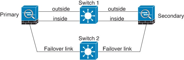
Scenario 1—Not Recommended
If a single switch or a set of switches are used to connect both failover and data interfaces between two ASAs, then when a switch or inter-switch-link is down, both ASAs become active. Therefore, the following two connection methods shown in the following figures are NOT recommended.


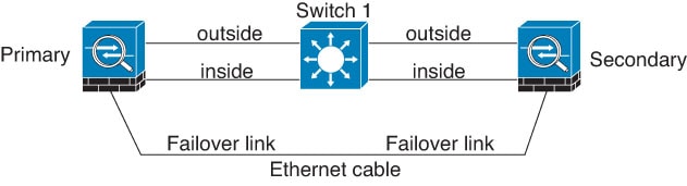
Scenario 2—Recommended
We recommend that failover links NOT use the same switch as the data interfaces. Instead, use a different switch or use a direct cable to connect the failover link, as shown in the following figures.
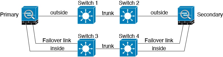
Scenario 3—Recommended
If the ASA data interfaces are connected to more than one set of switches, then a failover link can be connected to one of the switches, preferably the switch on the secure (inside) side of network, as shown in the following figure.
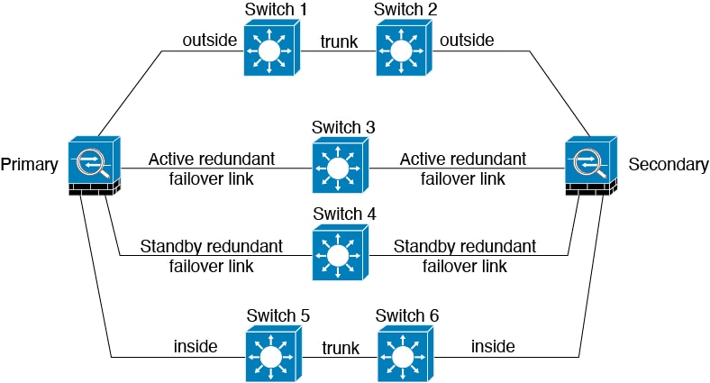
Scenario 4—Recommended
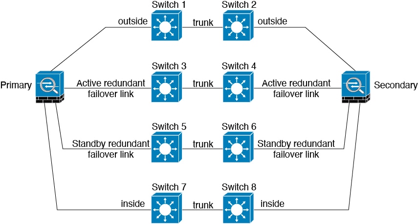
The most reliable failover configurations use a redundant interface on the failover link, as shown in the following figures.
MAC Addresses and IP Addresses in Failover
When you configure your interfaces, you can specify an active IP address and a standby IP address on the same network. Generally, when a failover occurs, the new active unit takes over the active IP addresses and MAC addresses. Because network devices see no change in the MAC to IP address pairing, no ARP entries change or time out anywhere on the network.
Note |
Although recommended, the standby address is not required. Without a standby IP address, the active unit cannot perform network tests to check the standby interface health; it can only track the link state. You also cannot connect to the standby unit on that interface for management purposes. |
The IP address and MAC address for the state link do not change at failover.
Active/Standby IP Addresses and MAC Addresses
For Active/Standby Failover, see the following for IP address and MAC address usage during a failover event:
-
The active unit always uses the primary unit's IP addresses and MAC addresses.
-
When the active unit fails over, the standby unit assumes the IP addresses and MAC addresses of the failed unit and begins passing traffic.
-
When the failed unit comes back online, it is now in a standby state and takes over the standby IP addresses and MAC addresses.
However, if the secondary unit boots without detecting the primary unit, then the secondary unit becomes the active unit and uses its own MAC addresses, because it does not know the primary unit MAC addresses. When the primary unit becomes available, the secondary (active) unit changes the MAC addresses to those of the primary unit, which can cause an interruption in your network traffic. Similarly, if you swap out the primary unit with new hardware, a new MAC address is used.
Virtual MAC addresses guard against this disruption, because the active MAC addresses are known to the secondary unit at startup, and remain the same in the case of new primary unit hardware. If you do not configure virtual MAC addresses, you might need to clear the ARP tables on connected routers to restore traffic flow. The ASA does not send gratuitous ARPs for static NAT addresses when the MAC address changes, so connected routers do not learn of the MAC address change for these addresses.
Active/Active IP Addresses and MAC Addresses
For Active/Active failover, see the following for IP address and MAC address usage during a failover event:
-
The primary unit autogenerates active and standby MAC addresses for all interfaces in failover group 1 and 2 contexts. You can also manually configure the MAC addresses if necessary, for example, if there are MAC address conflicts.
-
Each unit uses the active IP addresses and MAC addresses for its active failover group, and the standby addresses for its standby failover group. For example, the primary unit is active for failover group 1, so it uses the active addresses for contexts in failover group 1. It is standby for the contexts in failover group 2, where it uses the standby addresses.
-
When a unit fails over, the other unit assumes the active IP addresses and MAC addresses of the failed failover group and begins passing traffic.
-
When the failed unit comes back online, and you enabled the preempt option, it resumes the failover group.
Virtual MAC Addresses
The ASA has multiple methods to configure virtual MAC addresses. We recommend using only one method. If you set the MAC address using multiple methods, the MAC address used depends on many variables, and might not be predictable. Manual methods include the interface mode mac-address command, the failover mac address command, and for Active/Active failover, the failover group mode mac address command, in addition to autogeneration methods described below.
In multiple context mode, you can configure the ASA to generate virtual active and standby MAC addresses automatically for shared interfaces, and these assignments are synced to the secondary unit (see the mac-address auto command). For non-shared interfaces, you can manually set the MAC addresses for Active/Standby mode (Active/Active mode autogenerates MAC addresses for all interfaces).
For Active/Active failover, virtual MAC addresses are always used, either with default values or with values you can set per interface.
Intra- and Inter-Chassis Module Placement for the ASA Services Module
You can place the primary and secondary ASASMs within the same switch or in two separate switches.
Intra-Chassis Failover
If you install the secondary ASASM in the same switch as the primary ASASM, you protect against module-level failure.
Even though both ASASMs are assigned the same VLANs, only the active module takes part in networking. The standby module does not pass any traffic.
The following figure shows a typical intra-switch configuration.

Inter-Chassis Failover
To protect against switch-level failure, you can install the secondary ASASM in a separate switch. The ASASM does not coordinate failover directly with the switch, but it works harmoniously with the switch failover operation. See the switch documentation to configure failover for the switch.
For the best reliability of failover communications between ASASMs, we recommend that you configure an EtherChannel trunk port between the two switches to carry the failover and state VLANs.
For other VLANs, you must ensure that both switches have access to all firewall VLANs, and that monitored VLANs can successfully pass hello packets between both switches.
The following figure shows a typical switch and ASASM redundancy configuration. The trunk between the two switches carries the failover ASASM VLANs (VLANs 10 and 11).
Note |
ASASM failover is independent of the switch failover operation; however, ASASM works in any switch failover scenario. |

If the primary ASASM fails, then the secondary ASASM becomes active and successfully passes the firewall VLANs.

If the entire switch fails, as well as the ASASM (such as in a power failure), then both the switch and the ASASM fail over to their secondary units.

Stateless and Stateful Failover
The ASA supports two types of failover, stateless and stateful for both the Active/Standby and Active/Active modes.
Note |
Some configuration elements for clientless SSL VPN (such as bookmarks and customization) use the VPN failover subsystem, which is part of Stateful Failover. You must use Stateful Failover to synchronize these elements between the members of the failover pair. Stateless failover is not recommended for clientless SSL VPN. |
Stateless Failover
When a failover occurs, all active connections are dropped. Clients need to reestablish connections when the new active unit takes over.
Note |
Some configuration elements for clientless SSL VPN (such as bookmarks and customization) use the VPN failover subsystem, which is part of Stateful Failover. You must use Stateful Failover to synchronize these elements between the members of the failover pair. Stateless (regular) failover is not recommended for clientless SSL VPN. |
Stateful Failover
When Stateful Failover is enabled, the active unit continually passes per-connection state information to the standby unit, or in Active/Active failover, between the active and standby failover groups. After a failover occurs, the same connection information is available at the new active unit. Supported end-user applications are not required to reconnect to keep the same communication session.
Supported Features
For Stateful Failover, the following state information is passed to the standby ASA:
-
NAT translation table.
-
TCP and UDP connections and states. Other types of IP protocols, and ICMP, are not parsed by the active unit, because they get established on the new active unit when a new packet arrives.
-
The HTTP connection table (unless you enable HTTP replication).
-
The HTTP connection states (if HTTP replication is enabled)—By default, the ASA does not replicate HTTP session information when Stateful Failover is enabled. We suggest that you enable HTTP replication.
-
The ARP table
-
The Layer 2 bridge table (for bridge groups)
-
The ISAKMP and IPsec SA table
-
GTP PDP connection database
-
SIP signaling sessions and pin holes.
-
ICMP connection state—ICMP connection replication is enabled only if the respective interface is assigned to an asymmetric routing group.
-
Static and dynamic routing tables—Stateful Failover participates in dynamic routing protocols, like OSPF and EIGRP, so routes that are learned through dynamic routing protocols on the active unit are maintained in a Routing Information Base (RIB) table on the standby unit. Upon a failover event, packets travel normally with minimal disruption to traffic because the active secondary unit initially has rules that mirror the primary unit. Immediately after failover, the re-convergence timer starts on the newly active unit. Then the epoch number for the RIB table increments. During re-convergence, OSPF and EIGRP routes become updated with a new epoch number. Once the timer is expired, stale route entries (determined by the epoch number) are removed from the table. The RIB then contains the newest routing protocol forwarding information on the newly active unit.
Note
Routes are synchronized only for link-up or link-down events on an active unit. If the link goes up or down on the standby unit, dynamic routes sent from the active unit may be lost. This is normal, expected behavior.
-
DHCP Server—DHCP address leases are not replicated. However, a DHCP server configured on an interface will send a ping to make sure an address is not being used before granting the address to a DHCP client, so there is no impact to the service. State information is not relevant for DHCP relay or DDNS.
-
Cisco IP SoftPhone sessions—If a failover occurs during an active Cisco IP SoftPhone session, the call remains active because the call session state information is replicated to the standby unit. When the call is terminated, the IP SoftPhone client loses connection with the Cisco Call Manager. This connection loss occurs because there is no session information for the CTIQBE hangup message on the standby unit. When the IP SoftPhone client does not receive a response back from the Call Manager within a certain time period, it considers the Call Manager unreachable and unregisters itself.
-
RA VPN—Remote access VPN end users do not have to reauthenticate or reconnect the VPN session after a failover. However, applications operating over the VPN connection could lose packets during the failover process and not recover from the packet loss.
Unsupported Features
For Stateful Failover, the following state information is not passed to the standby ASA:
-
The user authentication (uauth) table
-
TCP state bypass connections
-
Multicast routing.
-
State information for modules, such as the ASA FirePOWER module.
-
Selected clientless SSL VPN features:
-
Smart Tunnels
-
Port Forwarding
-
Plugins
-
Java Applets
-
IPv6 clientless or Anyconnect sessions
-
Citrix authentication (Citrix users must reauthenticate after failover)
-
Transparent Firewall Mode Bridge Group Requirements for Failover
There are special considerations for failover when using bridge groups.
Transparent Mode Bridge Group Requirements for Appliances, ASAv
When the active unit fails over to the standby unit, the connected switch port running Spanning Tree Protocol (STP) can go into a blocking state for 30 to 50 seconds when it senses the topology change. To avoid traffic loss while the port is in a blocking state, you can configure one of the following workarounds depending on the switch port mode:
-
Access mode—Enable the STP PortFast feature on the switch:
interface interface_id
  spanning-tree portfast
The PortFast feature immediately transitions the port into STP forwarding mode upon linkup. The port still participates in STP. So if the port is to be a part of the loop, the port eventually transitions into STP blocking mode.
-
Trunk mode—Block BPDUs on the ASA on a bridge group's member interfaces with an EtherType access rule.
access-list id ethertype deny bpdu
access-group id in interface name1
access-group id in interface name2
Blocking BPDUs disables STP on the switch. Be sure not to have any loops involving the ASA in your network layout.
If neither of the above options are possible, then you can use one of the following less desirable workarounds that impacts failover functionality or STP stability:
-
Disable interface monitoring.
-
Increase interface holdtime to a high value that will allow STP to converge before the ASAs fail over.
-
Decrease STP timers to allow STP to converge faster than the interface holdtime.
Transparent Mode Bridge Group Requirements for the ASA Services Module
To avoid loops when you use failover with bridge groups, you should allow BPDUs to pass (the default), and you must use switch software that supports BPDU forwarding.
Loops can occur if both modules are active at the same time, such as when both modules are discovering each other’s presence, or due to a bad failover link. Because the ASASMs bridge packets between the same two VLANs, loops can occur when packets between bridge group member interfaces get endlessly replicated by both ASASMs. The spanning tree protocol can break such loops if there is a timely exchange of BPDUs. To break the loop, BPDUs sent between VLAN 200 and VLAN 201 need to be bridged.

Failover Health Monitoring
The ASA monitors each unit for overall health and for interface health. This section includes information about how the ASA performs tests to determine the state of each unit.
Unit Health Monitoring
The ASA determines the health of the other unit by monitoring the failover link with hello messages. When a unit does not receive three consecutive hello messages on the failover link, the unit sends LANTEST messages on each data interface, including the failover link, to validate whether or not the peer is responsive. The action that the ASA takes depends on the response from the other unit. See the following possible actions:
-
If the ASA receives a response on the failover link, then it does not fail over.
-
If the ASA does not receive a response on the failover link, but it does receive a response on a data interface, then the unit does not failover. The failover link is marked as failed. You should restore the failover link as soon as possible because the unit cannot fail over to the standby while the failover link is down.
-
If the ASA does not receive a response on any interface, then the standby unit switches to active mode and classifies the other unit as failed.
Interface Monitoring
You can monitor up to 1025 interfaces (in multiple context mode, divided between all contexts). You should monitor important interfaces. For example in multiple context mode, you might configure one context to monitor a shared interface: because the interface is shared, all contexts benefit from the monitoring.
When a unit does not receive hello messages on a monitored interface for 15 seconds (the default), it runs interface tests. (To change the period, see .) If one of the interface tests fails for an interface, but this same interface on the other unit continues to successfully pass traffic, then the interface is considered to be failed, and the ASA stops running tests.
If the threshold you define for the number of failed interfaces is met (see ), and the active unit has more failed interfaces than the standby unit, then a failover occurs. If an interface fails on both units, then both interfaces go into the “Unknown” state and do not count towards the failover limit defined by failover interface policy.
An interface becomes operational again if it receives any traffic. A failed ASA returns to standby mode if the interface failure threshold is no longer met.
If you have an ASA FirePOWER module, then the ASA also monitors the health of the module over the backplane interface. Failure of the module is considered a unit failure and will trigger failover. This setting is configurable.
If an interface has IPv4 and IPv6 addresses configured on it, the ASA uses the IPv4 addresses to perform the health monitoring. If an interface has only IPv6 addresses configured on it, then the ASA uses IPv6 neighbor discovery instead of ARP to perform the health monitoring tests. For the broadcast ping test, the ASA uses the IPv6 all nodes address (FE02::1).
Note |
If a failed unit does not recover and you believe it should not be failed, you can reset the state by entering the failover reset command. If the failover condition persists, however, the unit will fail again. |
Interface Tests
The ASA uses the following interface tests. The duration of each test is approximately 1.5 seconds by default, or 1/16 of the failover interface holdtime(see ).
-
Link Up/Down test—A test of the interface status. If the Link Up/Down test indicates that the interface is down, then the ASA considers it failed, and testing stops. If the status is Up, then the ASA performs the Network Activity test.
-
Network Activity test—A received network activity test. At the start of the test, each unit clears its received packet count for its interfaces. As soon as a unit receives any eligible packets during the test, then the interface is considered operational. If both units receive traffic, then testing stops. If one unit receives traffic and the other unit does not, then the interface on the unit that does not receive traffic is considered failed, and testing stops. If neither unit receives traffic, then the ASA starts the ARP test.
-
ARP test—A test for successful ARP replies. Each unit sends a single ARP request for the IP address in the most recent entry in its ARP table. If the unit receives an ARP reply or other network traffic during the test, then the interface is considered operational. If the unit does not receive an ARP reply, then the ASA sends a single ARP request for the IP address in the next entry in the ARP table. If the unit receives an ARP reply or other network traffic during the test, then the interface is considered operational. If both units receive traffic, then testing stops. If one unit receives traffic, and the other unit does not, then the interface on the unit that does not receive traffic is considered failed, and testing stops. If neither unit receives traffic, then the ASA starts the Broadcast Ping test.
-
Broadcast Ping test—A test for successful ping replies. Each unit sends a broadcast ping, and then counts all received packets. If the unit receives any packets during the test, then the interface is considered operational. If both units receive traffic, then testing stops. If one unit receives traffic, and the other unit does not, then the interface on the unit that does not receive traffic is considered failed, and testing stops. If neither unit receives traffic, then testing starts over again with the ARP test. If both units continue to receive no traffic from the ARP and Broadcast Ping tests, then these tests will continue running in perpetuity.
Interface Status
Monitored interfaces can have the following status:
-
Unknown—Initial status. This status can also mean the status cannot be determined.
-
Normal—The interface is receiving traffic.
-
Testing—Hello messages are not heard on the interface for five poll times.
-
Link Down—The interface or VLAN is administratively down.
-
No Link—The physical link for the interface is down.
-
Failed—No traffic is received on the interface, yet traffic is heard on the peer interface.
Failover Times
The following events trigger failover in a Firepower high availability pair:
-
More than 50% of the Snort instances on the active unit are down.
-
Disk space on the active unit is more than 90% full.
-
The no failover active command is run on the active unit or the failover active command is run on the standby unit.
-
The active unit has more failed interfaces than the standby unit.
-
Interface failure on the active device exceeds the threshold configured.
By default, failure of a single interface causes failover. You can change the default value by configuring a threshold for the number of interfaces or a percentage of monitored interfaces that must fail for the failover to occur. If the threshold breaches on the active device, failover occurs. If the threshold breaches on the standby device, the unit moves to Fail state.
To change the default failover criteria, enter the following command in global configuration mode:
Table 1. Command
Purpose
failover interface-policy num [%]
hostname (config)# failover interface-policy 20%Changes the default failover criteria.
When specifying a specific number of interfaces, the num argument can be from 1 to 250.
When specifying a percentage of interfaces, the num argument can be from 1 to 100.
Note |
If you manually fail over using the CLI or ASDM, or you reload the ASA, the failover starts immediately and is not subject to the timers listed below. |
|
Failover Condition |
Minimum |
Default |
Maximum |
|---|---|---|---|
|
Active unit loses power, hardware goes down, or the software reloads or crashes. When any of these occur, the monitored interfaces or failover link do not receives any hello message. |
800 milliseconds |
15 seconds |
45 seconds |
|
Active unit main board interface link down. |
500 milliseconds |
5 seconds |
15 seconds |
|
Active unit 4GE module interface link down. |
2 seconds |
5 seconds |
15 seconds |
|
Active unit FirePOWER module fails. |
2 seconds |
2 seconds |
2 seconds |
|
Active unit interface up, but connection problem causes interface testing. |
5 seconds |
25 seconds |
75 seconds |
Configuration Synchronization
Failover includes various types of configuration synchronization.
Running Configuration Replication
Running configuration replication occurs when any one or both of the devices in the failover pair boot.
In Active/Standby failover, configurations are always synchronized from the active unit to the standby unit.
In Active/Active failover, whichever unit boots second obtains the running configuration from the unit that boots first, regardless of the primary or secondary designation of the booting unit. After both units are up, commands entered in the system execution space are replicated from the unit on which failover group 1 is in the active state.
When the standby/second unit completes its initial startup, it clears its running configuration (except for the failover commands needed to communicate with the active unit), and the active unit sends its entire configuration to the standby/second unit. When the replication starts, the ASA console on the active unit displays the message “Beginning configuration replication: Sending to mate,” and when it is complete, the ASA displays the message “End Configuration Replication to mate.” Depending on the size of the configuration, replication can take from a few seconds to several minutes.
On the unit receiving the configuration, the configuration exists only in running memory. You should save the configuration to flash memory. For example, in Active/Active failover, enter the write memory all command in the system execution space on the unit that has failover group 1 in the active state. The command is replicated to the peer unit, which proceeds to write its configuration to flash memory.
Note |
During replication, commands entered on the unit sending the configuration may not replicate properly to the peer unit, and commands entered on the unit receiving the configuration may be overwritten by the configuration being received. Avoid entering commands on either unit in the failover pair during the configuration replication process. |
Note |
The crypto ca server command and related subcommands are not supported with failover; you must remove them using the no crypto ca server command. |
File Replication
Configuration syncing does not replicate the following files and configuration components, so you must copy these files manually so they match:
-
AnyConnect images
-
CSD images
-
AnyConnect profiles
The ASA uses a cached file for the AnyConnect client profile stored in cache:/stc/profiles, and not the file stored in the flash file system. To replicate the AnyConnect client profile to the standby unit, perform one of the following:
-
Enter the write standby command on the active unit.
-
Reapply the profile on the active unit.
-
Reload the standby unit.
-
-
Local Certificate Authorities (CAs)
-
ASA images
-
ASDM images
Command Replication
After startup, commands that you enter on the active unit are immediately replicated on the standby unit.You do not have to save the active configuration to flash memory to replicate the commands.
In Active/Active failover,changes entered in the system execution space are replicated from the unit on which failover group 1 is in the active state.
Failure to enter the changes on the appropriate unit for command replication to occur causes the configurations to be out of synchronization. Those changes may be lost the next time the initial configuration synchronization occurs.
The following commands are replicated to the standby ASA:
-
All configuration commands except for mode, firewall , and failover lan unit
-
copy running-config startup-config
-
delete
-
mkdir
-
rename
-
rmdir
-
write memory
The following commands are not replicated to the standby ASA:
-
All forms of the copy command except for copy running-config startup-config
-
All forms of the write command except for write memory
-
debug
-
failover lan unit
-
firewall
-
show
-
terminal pager and pager
About Active/Standby Failover
Active/Standby failover lets you use a standby ASA to take over the functionality of a failed unit. When the active unit fails, the standby unit becomes the active unit.
Note |
For multiple context mode, the ASA can fail over the entire unit (including all contexts) but cannot fail over individual contexts separately. |
Primary/Secondary Roles and Active/Standby Status
The main differences between the two units in a failover pair are related to which unit is active and which unit is standby, namely which IP addresses to use and which unit actively passes traffic.
However, a few differences exist between the units based on which unit is primary (as specified in the configuration) and which unit is secondary:
-
The primary unit always becomes the active unit if both units start up at the same time (and are of equal operational health).
-
The primary unit MAC addresses are always coupled with the active IP addresses. The exception to this rule occurs when the secondary unit becomes active and cannot obtain the primary unit MAC addresses over the failover link. In this case, the secondary unit MAC addresses are used.
Active Unit Determination at Startup
The active unit is determined by the following:
-
If a unit boots and detects a peer already running as active, it becomes the standby unit.
-
If a unit boots and does not detect a peer, it becomes the active unit.
-
If both units boot simultaneously, then the primary unit becomes the active unit, and the secondary unit becomes the standby unit.
Failover Events
In Active/Standby failover, failover occurs on a unit basis. Even on systems running in multiple context mode, you cannot fail over individual or groups of contexts.
The following table shows the failover action for each failure event. For each failure event, the table shows the failover policy (failover or no failover), the action taken by the active unit, the action taken by the standby unit, and any special notes about the failover condition and actions.
|
Failure Event |
Policy |
Active Unit Action |
Standby Unit Action |
Notes |
|---|---|---|---|---|
|
Active unit failed (power or hardware) |
Failover |
n/a |
Become active Mark active as failed |
No hello messages are received on any monitored interface or the failover link. |
|
Formerly active unit recovers |
No failover |
Become standby |
No action |
None. |
|
Standby unit failed (power or hardware) |
No failover |
Mark standby as failed |
n/a |
When the standby unit is marked as failed, then the active unit does not attempt to fail over, even if the interface failure threshold is surpassed. |
|
Failover link failed during operation |
No failover |
Mark failover link as failed |
Mark failover link as failed |
You should restore the failover link as soon as possible because the unit cannot fail over to the standby unit while the failover link is down. |
|
Failover link failed at startup |
No failover |
Become active Mark failover link as failed |
Become active Mark failover link as failed |
If the failover link is down at startup, both units become active. |
|
State link failed |
No failover |
No action |
No action |
State information becomes out of date, and sessions are terminated if a failover occurs. |
|
Interface failure on active unit above threshold |
Failover |
Mark active as failed |
Become active |
None. |
|
Interface failure on standby unit above threshold |
No failover |
No action |
Mark standby as failed |
When the standby unit is marked as failed, then the active unit does not attempt to fail over even if the interface failure threshold is surpassed. |
About Active/Active Failover
This section describes Active/Active failover.
Active/Active Failover Overview
In an Active/Active failover configuration, both ASAs can pass network traffic. Active/Active failover is only available to ASAs in multiple context mode. In Active/Active failover, you divide the security contexts on the ASA into a maximum of 2 failover groups.
A failover group is simply a logical group of one or more security contexts. You can assign failover group to be active on the primary ASA, and failover group 2 to be active on the secondary ASA. When a failover occurs, it occurs at the failover group level. For example, depending on interface failure patterns, it is possible for failover group 1 to fail over to the secondary ASA, and subsequently failover group 2 to fail over to the primary ASA. This event could occur if the interfaces in failover group 1 are down on the primary ASA but up on the secondary ASA, while the interfaces in failover group 2 are down on the secondary ASA but up on the primary ASA.
The admin context is always a member of failover group 1. Any unassigned security contexts are also members of failover group 1 by default. If you want Active/Active failover, but are otherwise uninterested in multiple contexts, the simplest configuration would be to add one additional context and assign it to failover group 2.
Note |
When configuring Active/Active failover, make sure that the combined traffic for both units is within the capacity of each unit. |
Note |
You can assign both failover groups to one ASA if desired, but then you are not taking advantage of having two active ASAs. |
Primary/Secondary Roles and Active/Standby Status for a Failover Group
As in Active/Standby failover, one unit in an Active/Active failover pair is designated the primary unit, and the other unit the secondary unit. Unlike Active/Standby failover, this designation does not indicate which unit becomes active when both units start simultaneously. Instead, the primary/secondary designation does two things:
-
The primary unit provides the running configuration to the pair when they boot simultaneously.
-
Each failover group in the configuration is configured with a primary or secondary unit preference. When used with preemption, this preference ensures that the failover group runs on the correct unit after it starts up. Without preemption, both groups run on the first unit to boot up.
Active Unit Determination for Failover Groups at Startup
The unit on which a failover group becomes active is determined as follows:
-
When a unit boots while the peer unit is not available, both failover groups become active on the unit.
-
When a unit boots while the peer unit is active (with both failover groups in the active state), the failover groups remain in the active state on the active unit regardless of the primary or secondary preference of the failover group until one of the following occurs:
-
A failover occurs.
-
A failover is manually forced.
-
A preemption for the failover group is configured, which causes the failover group to automatically become active on the preferred unit when the unit becomes available.
-
Failover Events
In an Active/Active failover configuration, failover occurs on a failover group basis, not a system basis. For example, if you designate both failover groups as Active on the primary unit, and failover group 1 fails, then failover group 2 remains Active on the primary unit while failover group 1 becomes active on the secondary unit.
Because a failover group can contain multiple contexts, and each context can contain multiple interfaces, it is possible for all interfaces in a single context to fail without causing the associated failover group to fail.
The following table shows the failover action for each failure event. For each failure event, the policy (whether or not failover occurs), actions for the active failover group, and actions for the standby failover group are given.
|
Failure Event |
Policy |
Active Group Action |
Standby Group Action |
Notes |
|---|---|---|---|---|
|
A unit experiences a power or software failure |
Failover |
Become standby Mark as failed |
Become active Mark active as failed |
When a unit in a failover pair fails, any active failover groups on that unit are marked as failed and become active on the peer unit. |
|
Interface failure on active failover group above threshold |
Failover |
Mark active group as failed |
Become active |
None. |
|
Interface failure on standby failover group above threshold |
No failover |
No action |
Mark standby group as failed |
When the standby failover group is marked as failed, the active failover group does not attempt to fail over, even if the interface failure threshold is surpassed. |
|
Formerly active failover group recovers |
No failover |
No action |
No action |
Unless failover group preemption is configured, the failover groups remain active on their current unit. |
|
Failover link failed at startup |
No failover |
Become active |
Become active |
If the failover link is down at startup, both failover groups on both units become active. |
|
State link failed |
No failover |
No action |
No action |
State information becomes out of date, and sessions are terminated if a failover occurs. |
|
Failover link failed during operation |
No failover |
n/a |
n/a |
Each unit marks the failover link as failed. You should restore the failover link as soon as possible because the unit cannot fail over to the standby unit while the failover link is down. |


 Feedback