Cisco vEdge Device as a NAT Device

To achieve simplification and consistency, the Cisco SD-WAN solution has been rebranded as Cisco Catalyst SD-WAN. In addition, from Cisco IOS XE SD-WAN Release 17.12.1a and Cisco Catalyst SD-WAN Release 20.12.1, the following component changes are applicable: Cisco vManage to Cisco Catalyst SD-WAN Manager, Cisco vAnalytics to Cisco Catalyst SD-WAN Analytics, Cisco vBond to Cisco Catalyst SD-WAN Validator, Cisco vSmart to Cisco Catalyst SD-WAN Controller, and Cisco Controllers to Cisco Catalyst SD-WAN Control Components. See the latest Release Notes for a comprehensive list of all the component brand name changes. While we transition to the new names, some inconsistencies might be present in the documentation set because of a phased approach to the user interface updates of the software product.

Cisco vEdge device can act as a NAT device, both on the transport side and on the service side of the router. On the transport side, the NAT functionality allows traffic from a local site to flow directly to the Internet rather than being backhauled to a colo facility that provides NAT services for Internet access. The NAT function is performed as the traffic enters the overlay tunnel to the WAN transport. On the service side, NAT functionality allows traffic from the local site to traverse the NAT before entering the overlay tunnel.

Table 1. Feature History

Release

Description

Cisco SD-WAN 19.1

Feature introduced. Cisco vEdge device can act as a NAT device, both on the transport side and on the service side of the router. On the transport side, the NAT functionality allows traffic from a local site to flow directly to the Internet rather than being backhauled to a colo facility that provides NAT services for Internet access.

Cisco vEdge Device as a NAT Device on the Transport Side

To provide users at a local site with direct, secure access to Internet resources, such as websites, you can configure the Cisco vEdge device to function as a Network Address Translation (NAT) device, performing both address and port translation (NAPT). Enabling NAT allows traffic exiting from a Cisco vEdge device to pass directly to the Internet rather than being backhauled to a colocation facility that provides NAT services for Internet access. Using NAT in this way on a Cisco vEdge device can eliminate traffic "tromboning" and allows for efficient routes, that have shorter distances, between users at the local site and the network-based applications that they use.

The figure below shows the router acting as a NAT device. The vEdge splits its traffic into two flows, which you can think of as two separate tunnels. One traffic flow, shown in green, remains within the overlay network and travels between the two routers in the usual fashion, on the secure IPsec tunnels that form the overlay network. The second traffic stream, shown in grey, is redirected through the Cisco vEdge device's NAT device and then out of the overlay network to a public network.

The NAT functionality on a Cisco vEdge device operates in a standard end-point independent fashion. The NAT software performs both address and port translation (NAPT). It establishes a translation entry between a private address and port pair inside the overlay network and a public address and port outside the overlay network. Once this translation entry is created, the NAT software allows incoming connections from an external host to be established with that private address and port only if that private address and port already established a connection to the external host. That is, an external host can reply to traffic from the private address and port; it cannot initiate a connection.

Cisco vEdge devices provide Application Layer Gateway (ALG) FTP support with Network Address Translation – Direct Internet Access (NAT-DIA) and Service NAT. Starting from Cisco SD-WAN Release 20.4.1 Service NAT support is extended to the FTP server. Service NAT was already supported for FTP ALG on the client side for Cisco SD-WAN Release 18.4.x and later releases.

From Cisco SD-WAN Release 20.4.1 the following scenarios are supported:
  1. Depending on the location of the FTP server and FTP client:
    • FTP client in private network and FTP server on the internet.
    • FTP server in private network and FP client on the internet.
  2. Depending on the type of connectivity present between the FTP client and FTP server:
    • FTP client and server are connected through NAT DIA.
    • FTP client and server are connected through overlay using service side NAT.

Transport-Side NAT Operation

The following figure explains how the NAT functionality on the Cisco vEdge device splits traffic into two flows (or two tunnels), so that some of it remains within the overlay network and some goes directly to the Internet or other public network.

In this figure, the Cisco vEdge device has two interfaces:

  • Interface ge0/1 faces the local site and is in VPN 1. Its IP address is 10.1.12.0/24.

  • Interface ge0/0 faces the transport cloud and is in VPN 0 (the transport VPN). Its IP address is 192.23.100.0/24, and it uses the default OMP port number, 12346, for overlay network tunnels.

To configure the Cisco vEdge device to act as a NAT device so that some traffic from the router can go directly to a public network, you do three things:

  • Enable NAT in the transport VPN (VPN 0) on the WAN-transport–facing interface, which here is ge0/0. All traffic exiting from the Cisco vEdge device, going either to other overlay network sites or to a public network, passes through this interface.

  • To direct data traffic from other VPNs to exit from the Cisco vEdge device directly to a public network, enable NAT in those VPNs or ensure that those VPNs have a route to VPN 0.

  • On the vCisco Catalyst SD-WAN Controller, create a centralized data policy the redirects the desired data traffic from the non-transport VPN to VPN 0, and then apply that data policy to the non-transport VPN. In this case, we apply the policy to VPN 1.

Once NAT is enabled on the Cisco vEdge device, data traffic affected by the centralized data policy (here, the data traffic from VPN 1) is split into two flows:

  • Traffic destined for another Cisco vEdge device in the overlay network remains in VPN 1, and it travels directly through the IPsec data plane tunnel from the source Cisco vEdge device to the destination Cisco vEdge device. This traffic never passes through VPN 0, and therefore it is never touched by NAT.

  • Traffic destined for the public network passes from VPN 1 to VPN 0, where it is NATed. During the NAT processing, the source IP address is changed from 10.1.12.0/24 to that of ge0/0, 179.23.100.0/24, and the source port is changed to 1024.

When NAT is enabled, all traffic that passes through VPN 0 is NATed. This includes both the data traffic from VPN 1 that is destined for a public network, and all control traffic, including the traffic required to establish and maintain DTLS control plane tunnels between the Cisco vEdge device and the Cisco Catalyst SD-WAN Controller and between the router and the Cisco Catalyst SD-WAN Validator.

The Cisco Catalyst SD-WAN Validator learns both the public and private addresses of the Cisco vEdge device, and it advertises both address to the Cisco Catalyst SD-WAN Controller. In turn, the Cisco Catalyst SD-WAN Controller advertises both addresses to all the devices in its domain. Each Cisco vEdge device then decides whether to use the public or the private address to communicate with another Cisco vEdge device as follows:

  • If the Cisco vEdge device is located at the same site as the other router (that is, if they are both configured with the same overlay network site ID), it communicates using the private address. Because both routers have the same site ID, they are behind the same NAT, and so their communication channels are already secure.

  • If the Cisco vEdge device route is at a different site, it communicates with the other router using the public address. Then, the NAT functionality on the Cisco vEdge device translates the public address to the proper private address.

If a Cisco Catalyst SD-WAN Controller connected to a corporate NAT and a NAT-enabled Cisco vEdge device are located at the same physical overlay network site, you must configure them with different Cisco Catalyst SD-WAN site identifiers in order for them to be able to communicate. Similarly, if more than one NAT-enabled Cisco vEdge device is located at the same physical overlay network site, each one must be configured with a different site identifier.

Cisco vEdge Device as a Service-Side NAT Device

On a Cisco vEdge device, you can configure NAT on the service side of the router so that data traffic traverses the NAT before entering the overlay tunnel that is located in the transport VPN. The service-side NAT performs NAT to mask the IP address of data traffic it receives. You can configure both dynamic NAT and 1:1 static NAT on the Cisco vEdge device.

Service-Side NAT Operation

The following figure explains how the Cisco vEdge device provides NAT services on the service side:

In this figure, the Cisco vEdge device has one NAT interface in VPN 1. This interface pools all service-side traffic destined for the NAT interface. The interface name is natpool2, and its IP address is 192.168.10.1. This IP address is the address each packet's IP address is translated to.

To configure the service-side NAT operation on the Cisco vEdge device so that traffic traverses the NAT in VPN 1 before being placed on the transport tunnel towards its destination, you do two things:

  • Create a NAT pool interface in VPN 1, the service-side VPN. Here, the NAT pool number is 2.

  • To direct data traffic from prefixes within VPN 1 to the service-side NAT, create a centralized data policy on the vSmart controller. In the match condition, specify the prefixes to be NATed. In the action condition, set the desired NAT pool, here, natpool 2. Then apply the data policy to the desired site (here, site 500), and apply it to traffic coming from the service side.

When service-side NAT is enabled, all matching prefixes in VPN 1 are directed to the natpool2 interface. This traffic is NATed, with the NAT swapping out the service-side IP address and replacing it with its NAT pool IP address. The packet then gets forwarded to its destination, here the data center.

Configure Local Internet Exit

To configure a Cisco vEdge device to be an Internet exit point, you enable NAT within a VPN on the Cisco vEdge device, and then you configure a centralized data policy on a Cisco vSmart controller. This policy splits the traffic within the VPN so that some of it is directed towards remote sites within the VPN, and hence remains within the overlay network, and other traffic is directed to the Internet or other destinations outside the overlay network. It is also possible to configure a Cisco vEdge device to forward data traffic directly to the Internet, by specifying the destination IP prefix.

NAT Configuration Considerations

When configuring a Cisco vEdge device to act as a NAT device, keep the following considerations in mind:

  • For a Cisco vEdge device that is acting as a vBond orchestrator, do not enable NAT operation on the interface that is tied to the vBond orchestrator's IP address. If you do so, the orchestrator is placed into a private address space behind the NAT. For the overlay network to function properly, the vBond orchestrator must be in a public address space. You can, however, enable NAT operation on other Cisco vEdge device interfaces.

  • When you enable NAT on a Cisco vEdge device, the router NATs all traffic that is sent out through VPN 0. That is, both data traffic and control traffic are NATed.

  • The NAT operation on outgoing traffic is performed in VPN 0, which is always only a transport VPN. The router's connection to the Internet is in VPN 0. Performing the NAT operation in VPN 0 avoids the IPsec tunnels that carry data traffic within the overlay network.

  • If you configure NAT on multiple interfaces in VPN 0, ECMP is performed among the interfaces.

  • When you use NAT—either by configuring it on an interface or by setting it as an action in a centralized data policy—no route lookup is performed. Instead, traffic is forwarded to one of the available NAT default gateways.

  • The Cisco vEdge device NAT implementation uses end-point–independent NAT. If your network contains other NAT devices that interact with the Cisco vEdge device NAT, these devices must either perform end-point–independent NAT, or they must be configured with policy rules so that they do not change the port numbers for Cisco Catalyst SD-WAN overlay network destinations.

  • When a Cisco vEdge device has two or more NAT interfaces, and hence two or more DIA connections to the internet, by default, data traffic is forwarding on the NAT interfaces using ECMP. To direct data traffic to a specific DIA interface, configure a centralized data policy on the Cisco vSmart controller that sets two actions—nat and local-tloc color. In the local-tloc color action, specify the color of the TLOC that connects to the desired DIA connection.

  • Interface IP has to be lesser than NAT range start IP. It is required for IP address of the NAT interface to be lower than the IP addresses used for the IP NAT pool range and static NAT translations. When this requirement is not met, the error is displayed and the configuration will be rejected. When NAT interface IP is higher than the static NAT mapping IP entry, error "Source address is not in the range of the interface IP prefix" displays. The address assigned to the interface IP is in the same subnet as the static mapping IP.

    For example, interface IP is 192.168.1.100/24, and the natpool has a range of 192.168.1.10 to 192.168.1.30 with a static mapping of the translated address 192.168.1.10, configuration will be rejected, error will displayed.

    If the interface IP is lower than the natpool range and static mapping, it allows to commit the configuration with no issues, configuration will be accepted.

    For example, interface IP is 192.168.1.1, and the natpool has a range of 192.168.1.10 to 192.168.1.30 with a static mapping of the translated address 192.168.1.10, configuration will be accepted as the interface IP is lower than the natpool range and static mapping, it allows to commit the configuration with no issues.

Direct Traffic to Exit to the Internet Using Data Policy

To use a centralized data policy to direct traffic from a Cisco vEdge device directly to the Internet, you enable NAT functionality in the WAN VPN or VPNs, and then you create and apply a centralized data policy.

Enable NAT Functionality in the WAN VPN

The first step in setting up Internet exit on a Cisco vEdge device is to configure the router to act as a NAT device. You do this by enabling NAT functionality in VPNs that have interfaces that connect to a WAN transport network. By default, VPN 0 always connects to the WAN transport. Other VPNs in your network might also connect to WANs.

To configure a Cisco vEdge device to act as a NAT device:

  1. Enable NAT in the desired VPN:

    vEdge(config)# vpn vpn-id interface interface-name nat
  2. By default, NAT mappings from the Cisco Catalyst SD-WAN overlay network side of the NAT to the external side of the NAT remain active, and NAT mapping timers are refreshed regularly to keep the mapping operational. To also refresh NAT mappings of packets coming from the external side of the NAT into the overlay network, change the refresh behavior:

    vEdge(config-nat)# refresh bi-directional
  3. NAT sessions time out after a period of non-use. By default, TCP sessions time out after 60 minutes, and UDP sessions time out after 20 minutes. To change these times:

    vEdge(config-nat)# tcp-timeout minutes
    vEdge(config-nat)# udp-timeout minutes

    The times can be from 1 to 65535 minutes.

    The following NAT session timers are fixed, and you cannot modify them:

    • TCP session timeout if no SYN-ACK response is received—5 seconds

    • TCP session timeout if three-way handshaking is not established—10 seconds

    • TCP session timeout after receiving a FIN/RST packet—30 seconds

    • ICMP timeout—6 seconds

    • Other IP timeout—60 seconds

  4. By default, the Cisco vEdge device does not receive inbound ICMP error messages. However, NAT uses ICMP to relay error messages across a NAT. To have the router receive the NAT ICMP messages:

    vEdge(config-nat)# no block-icmp-error

    In case of a DDoS attack, you might want to return to the default, to again prevent the Cisco vEdge device from receiving inbound ICMP error messages.

Create a Data Policy to Direct Traffic to the Internet Exit

To direct data traffic from a Cisco vEdge device to an Internet exit point, you split the destination of the traffic within a VPN, sending some to remote sites in the VPN and directing the traffic that is destined to the Internet (or other destinations outside the overlay network) to exit directly from the local Cisco vEdge device to the external destination.

To split the traffic, configure a centralized data policy on a Cisco vSmart controller:

  1. Configure the source prefix of the data traffic:

    vSmart(config)# policy data-policy policy-name
    vSmart(data-policy)# vpn-list list-name
    vSmart(vpn-list)# sequence number
    vSmart(sequence)# match source-ip ip-prefix
  2. Configure the destination of the data traffic, either by IP prefix or by port number:

    vSmart(sequence)# match destination-ip ip-prefix​​
    vSmart(sequence)# match destination-port port-number
  3. Direct matching data traffic to the NAT functionality. You can optionally configure a packet counter.

    vSmart(sequence)# action accept
    vSmart(accept)# count counter-name
    vSmart(accept)# nat use-vpn 0
  4. Configure additional sequences, as needed, for other source prefixes and destination prefixes or ports, and for other VPNs.

  5. Change the default data policy accept default action from reject to accept. With this configuration, all non-matching data traffic is forwarded to service-side VPNs at remote sites instead of being dropped.

    vSmart(vpn-list)# default-action accept
  6. Apply the data policy to particular sites in the overlay network:

    vSmart(config)# apply-policy site-list list-name data-policy policy-name from-service

Direct Traffic To Exit to the Internet Based Only on IP Prefix

You can direct lcal data traffic to exit to the internet based only on the destination IP prefix. To configure this, in the service VPN, forward traffic that is destined towards an internet location to VPN 0, which is the WAN transport VPN:

vEdge(config)# vpn vpn-id
vEdge(config-vpn)# ip route prefix vpn 0

In the vpn command, specify the VPN ID of the service-side VPN from which you are sending the traffic. In the ip route command, prefix is the IPv4 prefix of the remote destination.The vpn 0 option configures the software to perform the route lookup in VPN 0 rather than in the service-side VPN. This is done because the service-side VPN cannot resolve the route.

For the traffic redirection to work, in VPN 0, you must enable NAT on the interface associated with the configured prefix:

vEdge(config)# vpn 0 interface interface-name nat

Here, the interface is the one to use to reach the destination prefix.

The following snippet illustrates the two parts of the configuration:

vEdge# show running-config vpn 1
vpn 1
 ...
 ip route 10.1.17.15/32 vpn 0
!
vEdge# show running-config vpn 0
vpn 0
 ...
 interface ge0/1
  ...
  nat
  !
  no shutdown
 !
!

To verify that the redirection is working properly, look at the output of the show ip routes command:

vEdge# show ip routes  
Codes Proto-sub-type:
  IA -> ospf-inter-area,
  E1 -> ospf-external1, E2 -> ospf-external2,
  N1 -> ospf-nssa-external1, N2 -> ospf-nssa-external2,
  e -> bgp-external, i -> bgp-internal
Codes Status flags:
  F -> fib, S -> selected, I -> inactive,
  B -> blackhole, R -> recursive

                                    PROTOCOL  NEXTHOP  NEXTHOP          NEXTHOP                                                   
VPN  PREFIX              PROTOCOL   SUB TYPE  IF NAME  ADDR             VPN      TLOC IP          COLOR            ENCAP  STATUS  
----------------------------------------------------------------------------------------------------------------------------------
0    0.0.0.0/0           static     -         ge0/0    10.1.15.13       -        -                -                -      F,S     
0    10.0.20.0/24        connected  -         ge0/3    -                -        -                -                -      F,S     
0    10.0.100.0/24       connected  -         ge0/7    -                -        -                -                -      F,S     
0    10.1.15.0/24        connected  -         ge0/0    -                -        -                -                -      F,S     
0    10.1.17.0/24        connected  -         ge0/1    -                -        -                -                -      F,S     
0    57.0.1.0/24         connected  -         ge0/6    -                -        -                -                -      F,S     
0    172.16.255.15/32    connected  -         system   -                -        -                -                -      F,S     
1    10.1.17.15/32       nat        -         ge0/1    -                0        -                -                -      F,S     
1    10.20.24.0/24       ospf       -         ge0/4    -                -        -                -                -      -       
1    10.20.24.0/24       connected  -         ge0/4    -                -        -                -                -      F,S     
1    10.20.25.0/24       omp        -         -        -                -        172.16.255.16    lte              ipsec  F,S     
1    56.0.1.0/24         connected  -         ge0/5    -                -        -                -                -      F,S     
1    60.0.1.0/24         omp        -         -        -                -        172.16.255.16    lte              ipsec  F,S     
1    61.0.1.0/24         omp        -         -        -                -        172.16.255.16    lte              ipsec  F,S     
512  10.0.1.0/24         connected  -         eth0     -                -        -                -                -      F,S  

In VPN 1, the prefix 10.1.17.15/32 is associated with the protocol "nat", which reflects the configuration of the ip route command in VPN 1. For this prefix, the next-hop interface is ge0/1, and the next-hop VPN is VPN 0. This prefix is installed into the route table only if the resolving next hop is over an interface on which NAT is enabled.

The prefix that you configure in the ip route represents a route in the specified VPN (the service VPN whose ID you enter in the first command above). To direct traffic to that prefix, you can redistribute it into BGP or OSPF:

vEdge(config-vpn)# bgp address-family  address-family  redistribute nat
​vEdge(config-vpn)# ospf redistribute nat

Track Transport Interface Status

When you enable NAT on a transport interface to allow the local router to forward traffic directly to the internet rather than first forwarding the traffic to a data center router connected to the internet, the router directs data traffic according to the centralized data policy that is applied to that interface, forwarding some traffic directly to the internet (or other external network) and other traffic to other VPNs in the overlay network, including the data center. If the internet or external network becomes unavailable, for example, due to a brownout, the router has no way to learn of this disruption, and it continues to forward traffic based on the policy rules. The result is that traffic that is being forwarded to the internet is silently dropped.

To prevent the internet-bound traffic from being dropped, you can configure the router to track the status of the transport interface and to redirect the traffic to the non-NATed tunnel on the transport interface when the local internet is unavailable. With tracking enabled, the router periodically probes the path to the internet to determine whether it is up. When it detects that the path is down, the router withdraws the NAT route to the internet destination, and reroutes the traffic to the non-NATed tunnel on the interface so that another router in the overlay network can forward the traffic to the internet. The local router continues to periodically check the status of the path to the interface. When it detects that the path is again functioning, the router reinstalls the NAT route to the internet.

To track the transport interface status, you create a global interface tracker, and then you apply it to the transport interface on which NAT is enabled.

To create a transport interface tracker:

vEdge(config)# system
vEdge(config-system)#  tracker tracker-name
vEdge(config-tracker)# endpoint-dns-name dns-name
vEdge(config-tracker)# endpoint-ip ip-address
vEdge(config-tracker)# interval seconds
vEdge(config-tracker)# multiplier number
vEdge(config-tracker)# threshold milliseconds

The tracker name can be up to 128 lowercase characters.

At a minimum, you must specify the IP address or DNS name of a destination on the internet. This is the destination to which the router sends probes to determine the status of the transport interface. You can configure either one IP address or one DNS name.

By default, a status probe is sent every minute (60 seconds). To modify this value, change the time in the interval command to a value from 10 through 600 seconds.

By default, the router waits 300 milliseconds to receive a response from the internet destination. To modify the time to wait for a response, change the time in the threshold command to a value from 100 through 1000 milliseconds.

By default, after sending three probes and receiving no responses, the router declares that transport interface is down. To modify the number of retries, change the number in the multiplier command to a value from 1 through 10.

You can configure up to eight interface trackers.

To apply a tracker to a transport interface:

vEdge(config)# vpn 0
vEdge(vpn)# interface interface-name
vEdge(interface)# tracker tracker-name

You can apply only one tracker to an interface.

Configure Service-Side NAT

You can configure both dynamic NAT and 1:1 static NAT on the service side of a router. To do so, you create a NAT pool interface within a service VPN on the router, and then you configure a centralized data policy on the Cisco vSmart controller. This policy directs data traffic with the desired prefixes to the service-side NAT. Finally, you configure either dynamic NAT or static NAT on the desired NAT pool interfaces.

Create a NAT Pool Interface

On the router, you create a NAT pool interface. This interface NATs data traffic that is directed to it and then forwards the traffic towards its destination.

To create a NAT pool interface:

  1. In the desired VPN, create the NAT pool interface:
    vEdge(config-vpn)# interface natpool number
    The pool can have a number from 1 through 31. You refer to this NAT pool number in the action portion of the centralized data policy that you configure to direct data traffic to the pool. You can configure a maximum of 31 NAT pool interfaces in a VPN.
  2. Configure the NAT pool interface's IP address:
    vEdge(config-natpool)#  ip address prefix/show ip routes length
    The length of the IP address determines the number of addresses that the router can NAT at the same time. For each NAT pool interface, you can configure a maximum of 250 IP addresses.
  3. Enable the interface:
    ​vEdge(config-natpool)# no shutdown

On a NAT pool interface, you can configure only these two commands (ip address and shutdown/no shutdown) and the nat command, discussed below. You cannot configure any of the other interface commands.

Here is an example of configuring the NAT pool interface:

vEdge# show running-config vpn 1
vpn 1
 interface ge0/4
  ip address 10.20.24.15/24
  no shutdown
 !
 interface ge0/5
  ip address 56.0.1.15/24
  no shutdown
 !
 interface natpool2
  ip address 192.179.10.1/32
  nat
  !
  no shutdown
 !
!

To display information about the NAT pool interface, use the show interface command:

vEdge# show interface vpn 1

                                 IF      IF                                                              TCP                                   
                                 ADMIN   OPER    ENCAP  PORT                              SPEED          MSS                 RX       TX       
VPN  INTERFACE  IP ADDRESS       STATUS  STATUS  TYPE   TYPE     MTU   HWADDR             MBPS   DUPLEX  ADJUST  UPTIME      PACKETS  PACKETS  
-----------------------------------------------------------------------------------------------------------------------------------------------
1    ge0/4      10.20.24.15/24   Up      Up      null   service  1500  00:0c:29:7d:1e:26  10     full    1420    0:01:24:06  566      565      
1    ge0/5      56.0.1.15/24     Up      Up      null   service  1500  00:0c:29:7d:1e:30  10     full    1420    0:01:24:06  26       4        
1    natpool2   192.179.10.1/32  Up      Up      null   service  1500  00:00:00:00:00:00  10     full    1420    0:00:40:57  0        0

Create a Data Policy To Direct Data Traffic to a Service-Side NAT

To direct data traffic from the service side of the router to the NAT, you create a centralized data policy on the Cisco vSmart controller. In the match condition of the policy, you identify the data traffic that you want to direct to the NAT. One way to do this is to match on the IP prefixes of the data traffic. In the action condition of the policy, you direct the matching traffic to one of the number NAT pools. Finally, you apply the policy to the service side at the desired overlay network sites.

To create a data policy to direct data traffic to a service-side NAT:

  1. Configure the lists required for the data policy. You must configure a list of VPN and sites. If you are matching on data prefixes, configure a data prefix list.
    vSmart(config-policy-lists)# vpn-list list-name
    vSmart(config-policy-vpn-list)# vpn vpn-id
    vSmart(config-policy-lists)# site-list list-name
    vSmart(config-policy-site-list)# site-id site-id
    vSmart(config-policy-lists)# data-prefix-list list-name
    vSmart(config-policy-data-prefix-list)# ip-prefix prefix/length
  2. Configure a data policy:
    vSmart(config-policy)# data-policy policy-name
    vSmart(config-data-policy)# vpn-list list-name
    vSmart(config-vpn-list)# sequence number
  3. Configure the desired match conditions:
    vSmart(config-sequence)# match condition
  4. In the action, associate matching data traffic with the desired NAT pool:
    vSmart(config-sequence)# action accept
    vSmart(config-sequence)# nat pool number
  5. Configure the desired default action for the data policy:
    vSmart(config-vpn-list)# default-action (accept | reject)
  6. Apply the policy to the desired sites in the overlay network:
    vSmart(config)# apply-policy site-list list-name data-policy policy-name from-service

Here is an example of configuring the centralized data policy:

vSmart# show running-config policy
policy
 data-policy service-side-nat-policy
  vpn-list vpn-1
   sequence 10
    match
     source-data-prefix-list prefixes-to-nat
    !
    action accept
     nat pool 2
    !
   !
   default-action accept
  !
 !
 lists
  vpn-list vpn-1
   vpn 1
  !
  data-prefix-list prefixes-to-nat
   ip-prefix 56.0.1.0/24
  !
  site-list site-500
   site-id 500
  !
 !
!
vSmart# show running-config apply-policy 
apply-policy
 site-list site-500
  data-policy service-side-nat-policy from-service
 !
!

After you activate the policy, you can see that it has been applied to the router:

vEdge# show policy from-vsmart
from-vsmart data-policy service-side-nat-policy
 direction from-service
 vpn-list vpn-1
  sequence 10
   match
    source-data-prefix-list prefixes-to-nat
   action accept
    nat pool 2
  default-action accept
from-vsmart lists vpn-list vpn-1
 vpn 1
from-vsmart lists data-prefix-list prefixes-to-nat
 ip-prefix 56.0.1.0/24

Here is an example of configuring NAT fallback behaviour:

vEdge# show policy from-vsmart
from-vsmart data-policy service-side-nat-policy
 direction from-service
 vpn-list vpn-1
 sequence 91
   match
    source-data-prefix-list RFC1918
   action accept
    nat use-vpn 0
    nat fallback
exit

Configure Dynamic NAT

By default, when you configure a router to act as a NAT, the router performs dynamic network address translation. In this capacity, the router can perform dynamic NAT for up to 250 IP addresses across NAT pools.

To configure dynamic NAT:

  1. In the desired VPN, create the NAT pool interface:
    vEdge(config-vpn)# interface natpool number
    The pool can have a number from 1 through 31. You refer to this NAT pool number in the action portion of the centralized data policy that you configure to direct data traffic to the pool. You can configure a maximum of 31 NAT pool interfaces in a VPN.
  2. Configure the IP address prefix for the NAT pool interface:
    vEdge(config-natpool)#  ip address prefix/length
    The prefix length determines the maximum number of addresses that the router can NAT at the same time. For example, for a /30 prefix length, the router can perform translation on four addresses at a time. For each NAT pool interface, you can configure a maximum of 250 IP addresses.
  3. Enable the interface:
    ​vEdge(config-natpool)# no shutdown
  4. Enable dynamic NAT:
    vEdge(config-natpool)# nat

As mentioned above, the length of the IP address determines the number of IP addresses that the router can NAT at the same time, up to a maximum of 250 across all NAT pools. When all available IP addresses have been used, the router reuses the last IP address multiple times, changing the port number. The port number is chosen at random from the nonreserved port numbers, that is, those port numbers in the range 1024 through 65535. For example, if the IP address is 10.1.17.3/30, the Cisco vEdge device can uniquely NAT four IP addresses. Let us say that the router maps the fourth IP address to 10.1.20.5, or more specifically to 10.1.20.5:12346 if we include the port number. It would then map the fifth IP address to the same IP address, but with a different port, such as 10.1.20.5:12347. To have the router drop packets when no more IP addresses are available for the translation process, include the following command:

vEdge(config)# vpn vpn-id interface  natpool number
vEdge(config-natpool)# no overload

Configure Static NAT

You can configure a router acting as a NAT to perform static network address translation (also called 1:1 static NAT) of source IP addresses. You can translate service-side source addresses before sending packets out to the overlay network, and you can translate external addresses before forwarding packets to the service-side network. You can also translate service-side source addresses before sending packets out to another service-side LAN connected to the same router.

For packets originating on the service side of a router, you can statically map the packets' source IP address to another IP address. You do this by creating a NAT pool interface within a service-side VPN. For this interface, you configure a pool of IP addresses to use for network address translation, and then you configure the static address mappings. When the address pool is depleted, you can choose to drop packets that have unmapped source IP addresses. (Dropping these packets is not the default behavior.)

For packets exiting a transport tunnel from a router, you can statically map the packet's source IP address to another IP address, generally to an address that is routable within the service-side network. You configure this in the same way as for NATing packets originating on the service side.

You must create separate NAT pool interfaces to translate source IP addresses for service-side packets and for tunnel packets.

Across all NAT pools, a vEdge router can NAT a maximum of 254 source IP addresses. This is the number of addresses in a /24 prefix, less the .0 and .255 addresses. You cannot configure translation for .0 and .255 addresses.

This section explains how to configure static NAT for translating service-side source IP addresses and for translating external (transport-side) IP addresses. The two procedures are very similar, but we describe them separately for clarity.

Static NATing of Service-Side Addresses

To configure the static NATing of service-side source IP addresses:

  1. In the desired VPN, create the NAT pool interface:

    vEdge(config-vpn)# interface natpool number

    The pool can have a number from 1 through 31. You refer to this NAT pool number in the action portion of the centralized data policy that you configure to direct data traffic to the pool. You can configure a maximum of 31 NAT pool interfaces in a VPN.

  2. Enable the NAT pool interface:

    ​vEdge(config-natpool)# no shutdown
  3. Configure the IP address prefix for the NAT pool interface

    vEdge(config-natpool)# ip address prefix/length

    The prefix length determines the maximum number of source IP addresses that can be NATed in the NAT pool. For example, for a /30 prefix length, a maximum of four source IP addresses can be NATed. For each NAT pool interface, you can configure a maximum of 250 IP addresses.

  4. Configure the NAT pool interface to perform network address translation:

    vEdge(config-natpool)# nat
  5. By default, all IP addresses are translated to an address in the pool of NAT addresses configured in the ip address command. The addresses are mapped one to one until the address pool is depleted. Then, the first address is used multiple times, and the port number is changed to a random value between 1024 and 65535. This reuse of the last address is called overloading. Overloading effectively implements dynamic NAT.

    To configure static NAT, include the no overload command to enforce the mapping of a single source IP address to a single translated IP address:

    vEdge(config-nat)# no overload

    With this command, when the maximum number of available IP addresses available to be translated is reached, packets with other IP addresses are dropped.

  6. Set the direction in which the NAT pool interface performs static mapping to inside to statically translate service-side IP source addresses:

    vEdge(config-nat)# direction inside

    Note that the default direction is inside.

    A single NAT pool interface can perform static address translation either for service-side source addresses (direction inside) or for external source addresses (direction outside), but not for both. This means that for a single NAT pool, you can configure only one direction command.

  7. Define the static address translations for service-side source IP addresses:

    vEdge(config-nat)# static source-ip ip-address1 translate-ip ip-address2 inside

    ip-address1 is the source IP address of a device or branch router on the service side of the Cisco vEdge device.

    ip-address2 is the translated source IP address. This is the address that the Cisco vEdge device places in the source field of the packet's IP header when transmitting the packet out the transport network. Because the NAT pool direction is inside, this IP address must be in the interface's IP address range. This is the IP address prefix configured in the ip address command.

    The inside option indicates that it is a service-side, or inside, address that is being statically translated. Note that the inside option in the static command is different from and independent of the inside or outside option you specify in the direction command. When you are statically NATing service-side addresses, you can statically map both service-side addresses (with a static...inside command) and transport-side addresses (with a static...outside command), as described in the next step. The maximum number of service-side source IP addresses that you can statically NAT is equal to the number of addresses available in the interface's prefix range. For example, for a /30 prefix length, you can configure a maximum of four static NAT mappings.

    Once the NAT static address mapping is installed in the router's NAT table, the router can perform source IP address translation in both directions—when a service-side packet is being transmitted into the transport network, and when an external packet (addressed to ip-address2) arrives at the router.

  8. Define the static address translations for transport-side source IP addresses:

    vEdge(config-nat)# static source-ip ip-address1 translate-ip ip-address2 outside

    ip-address1 is the source IP address of an external device or router, that is, of a device at a remote site.

    ip-address2 is the translated source IP address. This is the address that the vEdge router places in the source field of the packet's IP header before forwarding the traffic to the service-side network.

    The outside option indicates that an external IP address is being statically translated. Note that the outside option in the static command is different from and independent of the inside or outside option you specify in the direction command. When you are statically NATing service-side addresses, you can statically map both service-side addresses (with a static...inside command) and transport-side addresses (with a static...outside command), as described in the previous step.

    Because the direction of the NAT pool is inside, the pool of IP addresses set aside for NATing is used only to NAT service-side source IP addresses. This means that here, you can configure any number of external static address translations.

    As a corollary of NATing an external IP address, when a service-side device responds to that external IP address, it simply takes the source IP address from the received packet and places it into the destination IP field in the IP header.

  9. Optionally, log the creation and deletion of NAT flows:

    vEdge(config-nat)# log-translations

Static NATing of External Addresses

To configure the static NATing of external source IP addresses:

  1. In the desired VPN, create the NAT pool interface:

    vEdge(config-vpn)# interface natpool number

    The pool can have a number from 1 through 31. You refer to this NAT pool number in the action portion of the centralized data policy that you configure to direct data traffic to the pool. You can configure a maximum of 31 NAT pool interfaces in a VPN.

  2. Enable the NAT pool interface:​

    vEdge(config-natpool)# no shutdown
  3. Configure the IP address prefix for the NAT pool interface:

    vEdge(config-natpool)# ip address prefix/length

    The prefix length determines the maximum number of IP addresses that the router can NAT at the same time in that NAT pool. For example, for a /30 prefix length, the router can perform translation on four addresses at a time. For each NAT pool interface, you can configure a maximum of 250 IP addresses.

  4. Configure the NAT pool interface to perform network address translation:

    vEdge(config-natpool)# nat
  5. By default, all IP addresses are translated to an address in the pool of NAT addresses configured in the ip address command. The addresses are mapped one to one until the address pool is depleted. Then, the last address is used multiple times, and the port number is changed to a random value between 1024 and 65535. This reuse of the last address is called overloading. Overloading effectively implements dynamic NAT. To configure static NATing of external addresses, you must include the no overload command to enforce the mapping of a single source IP address to a single translated IP address, because the software does not support overloading on the outside NAT pool interface:

    vEdge(config-nat)# no overload

    With this command, when the maximum number of available IP addresses available to be translated is reached, packets with other IP addresses are dropped.

  6. Set the direction in which the NAT pool interface performs static mapping to outside to statically translate external IP source addresses:

    vEdge(config-nat)# direction outside

    The default direction is inside.

    A single NAT pool interface can perform static address translation either for service-side source addresses (direction inside) or for external source addresses (direction outside), but not for both. This means that for a single NAT pool, you can configure only one direction command.

  7. Define the static address translations for external source-IP addresses:

    vEdge(config-nat)# static source-ip ip-address1 translate-ip ip-address2 outside

    ip-address1 is the source IP address of a remote device or router on the transport side of the router.

    ip-address2 is the translated source IP address. This is the address that the router places in the source field of the packet's IP header when forwarding the packet into the service-side network. Because the NAT pool direction is outside, this IP address must be in the interface's IP address range. This is the IP address prefix configured in the ip address command.

    The outside option indicates that it is an external, or outside, address that is being statically translated. Note that the outside option in the static command is different from and independent of the inside or outside option you specify in the direction command. When you are statically NATing external addresses, you can statically map both transport-side addresses (with a static...outside command) and service-side addresses (with a static...inside command), as described in the previous step.

    The maximum number of external source IP addresses that you can statically NAT is equal to the number of addresses available in the interface's prefix range. For example, for a /30 prefix length, you can configure a maximum of four static NAT mappings.

    As a corollary of NATing an external IP address, when a service-side device responds to that external IP address, it simply takes the source IP address from the received packet and places it into the destination IP field in the IP header.

Configure Split DNS

When an application-aware routing policy allows a Cisco vEdge device to send application traffic to and receive application traffic from a service VPN, the router performs a Domain Name System (DNS) lookup to determine how to reach a server for the application. If the router does not have a connection to the internet, it sends DNS queries to a router that has such a connection, and that router determines how to reach a server for that application. In a network in which the internet-connect router is in a geographically distant data center, the resolved DNS address might point to a server that is also geographically distant from the site where the service VPN is located.

Because you can configure a Cisco vEdge device to be an internet exit point, it is possible for any router to reach the internet directly to perform DNS lookups. To do this, you create a policy that configures split DNS and that defines, on an application-by-application basis, how to perform DNS lookups.

You configure split DNS with either a centralized data policy or, if you want to apply SLA criteria to the data traffic, an application-aware routing policy. You create these policies on a Cisco vSmart controller, and they are pushed to the Cisco vEdge devices.

CLI Configuration Procedure

Configure Split DNS with a Centralized Data Policy

The following high-level steps show the minimum policy components required to enable split DNS with a centralized data policy:

  1. Create one or more lists of overlay network sites to which the centralized data policy is to be applied (in an apply-policy command):

    vSmart(config)# policy​
    vSmart(config-policy)# lists site-list list-name
    vSmart(config-lists)# site-id site-id

    The list can contain as many site IDs as necessary. Include one site-id command for each site ID. For contiguous site IDs, you can specify a range of numbers separated with a dash (–).

  2. Create lists of applications or application families for which you want to enable split DNS. You refer to these lists in the match section of the data policy.

    vSmart(config)# policy lists
    vSmart(config-lists)# app-list list-name
    vSmart(config-app-list)# (app application-name | app-family family-name)
  3. Create lists VPNs to which the split DNS policy is to be applied (in a policy data-policy command):

    vSmart(config)# policy lists
    vSmart(config-lists)# vpn-list list-name
    vSmart(config-lists)# vpn vpn-id
  4. Create a data policy instance and associate it with a list of VPNs:

    vSmart(config)# policy data-policy policy-name
    vSmart(config-data-policy)# vpn-list list-name
  5. Create a series of match–action pair sequences:

    vSmart(config-vpn-list)# sequence number

    The match–action pairs are evaluated in order, by sequence number, starting with the lowest numbered pair and ending when the route matches the conditions in one of the pairs. Or if no match occurs, the default action is taken (either rejecting the route or accepting it as is).

  6. Process the DNS server resolution for the applications or application families contained in an application list. In list-name, specify one of the names in a policy lists app-list command.

    ​​vSmart(config-sequence)# match dns-app-list list-name
  7. Configure the match–action pair sequence to process DNS requests (for outbound data traffic) or responses (for inbound data traffic):

    vSmart(config-sequence)# match dns (request | response)
  8. Accept matching packets, optionally counting and logging them:

    vSmart(config-sequence)# action  accept [count counter-name] [log]
  9. Enable local internet exit:

    vSmart(config-sequence)# action accept nat [pool number] [use-vpn 0]
  10. By default, the DNS servers configured in the VPN in which the policy is applied are used to process DNS lookups for the applications. You can direct DNS requests to a particular DNS server. For a data policy condition that applies to outbound traffic (from the service network), configure the IP address of the DNS server:

    vSmart(config-sequence)# action  accept redirect-dns ip-address

    For a data policy condition that applies to inbound traffic (from the tunnel), include the following so that the DNS response can be correctly forwarded back to the service VPN:

    vSmart(config-sequence)# action accept redirect-dns host
  11. f a route does not match any of the conditions in one of the sequences, it is rejected by default. To accept nonmatching prefixed, configure the default action for the policy:

    vSmart(config-policy-name)# default-action accept
  12. Apply the policy to one or more sites in the overlay network:

    vSmart(config)# apply-policy site-list list-name data-policy policy-name (all | from-service | from-tunnel)

Configure Split DNS with an Application-Aware Routing Policy

The following high-level steps show the minimum policy components required to enable split DNS with an application-aware routing policy:

  1. Create one or more lists of overlay network sites to which the centralized data policy is to be applied (in an apply-policy command):

    vSmart(config)# policy​
    vSmart(config-policy)# lists site-list list-name
    vSmart(config-lists-list-name)# site-id site-id

    The list can contain as many site IDs as necessary. Include one site-id command for each site ID. For contiguous site IDs, you can specify a range of numbers separated with a dash (–).

  2. Create SLA classes and traffic characteristics to apply to matching application data traffic:
    vSmart(config)# policy sla-class sla-class-name
    vSmart(config-sla-class)# jitter milliseconds
    vSmart(config-sla-class)# latency milliseconds
    vSmart(config-sla-class)# loss percentage
  3. Create lists of applications or application families to identify application traffic of interest in the match section of the data policy:

    vSmart(config)# policy lists
    vSmart(config-lists)# app-list list-name
    vSmart(config-app-list)# (app application-name | app-family family-name)
  4. Create lists VPNs to which the split DNS policy is to be applied (in a policy data-policy command):

    vSmart(config)# policy lists
    vSmart(config-lists)# vpn-list list-name
    vSmart(config-lists-list-name)# vpn vpn-id
  5. If you are configuring a logging action, configure how often to log packets to syslog files:

    vEdge(config)# policy log-frequency number
  6. Create an application-aware routing policy instance and associate it with a list of VPNs:

    vSmart(config)# policy app-route-policy policy-name
    vSmart(config-data-policy-policy-name)# vpn-list list-name
  7. Create a series of match–pair sequences:

    vSmart(config-vpn-list)# sequence number

    The match–action pairs are evaluated in order, by sequence number, starting with the lowest numbered pair and ending when the route matches the conditions in one of the pairs. Or if no match occurs, the default action is taken (either rejecting the route or accepting it as is).

  8. Process the DNS server resolution for the applications or application families contained in an application list. In list-name, specify one of the names in a policy lists app-list command.

    ​​vSmart(config-sequence-number)# match dns-app-list list-name
  9. Configure the match–action pair sequence to process s DNS requests (for outbound data traffic) or responses (for inbound data traffic):

    vSmart(config-sequence-number)# match (request | response)
  10. Define the SLA action to take if a match occurs:

    vSmart(config-sequence)# action sla-class sla-class-name [strict]    
    vSmart(config-sequence)# action sla-class sla-class-name [strict] preferred-color colors
    vSmart(config-sequence)# action backup-sla-preferred-color colors
  11. For matching packets, optionally count and log them:

    vSmart(config-sequence)# action count counter-name
    vSmart(config-sequence)# action  log
  12. Enable local internet exit:

    vSmart(config-sequence-number)# action acccept nat [pool number] [use-vpn 0]
  13. If a packet does not match any of the conditions in one of the sequences, a default action is taken. For application-aware routing policy, the default action is to accept nonmatching traffic and forward it with no consideration of SLA. You can configure the default action so that SLA parameters are applied to nonmatching packets:

    vSmart(config-policy-name)# default-action sla-class sla-class-name
  14. Apply the policy to one or more sites in the overlay network:

    vSmart(config)# apply-policy site-list list-name app-route-policy policy-name

Structural Components of Policy Configuration for Split DNS

Below are the structural components required to configure split DNS on a vSmart controller. The components related to configuring split DNS are explained in the sections below. For an explanation of the data policy and application-aware routing policy components that are not specifically related to split DNS, see Configure Centralized Data Policy and Configure Application-Aware Routing.

policy
  lists
    app-list list-name
      (app application-name | app-family application-family)
    site-list list-name 
      site-id site-id 
    vpn-list list-name 
      vpn-id vpn-id 
 data-policy policy-name 
   vpn-list list-name 
     sequence number 
       match
         dns (request | response)
         dns-app-list list-name
       action accept
         count counter-name
         log
         nat use-vpn 0
         redirect-dns (ip-address | host)
     default-action
       (accept | drop)
apply-policy 
  site-list list-name data-policy policy-name (all | from-service | from-tunnel)
policy
  lists
    app-list list-name
      (app application-name | app-family application-family)
    site-list list-name
      site-id site-id
    vpn-list list-name
      vpn-id vpn-id
log-frequency number
sla-class sla-class-name
  jitter milliseconds
  latency milliseconds
  loss percentage
app-route-policy policy-name
   vpn-list list-name
     sequence number
       match
         dns (request | response)
         dns-app-list list-name
       action
         backup-sla-preferred-color colors
         count counter-name
         log
         nat use-vpn 0
         sla-class sla-class-name [strict] [preferred-color colors]
     default-action
       sla-class sla-class-name
apply-policy
  site-list list-name app-route-policy policy-name

Lists

A data policy or an application-aware routing policy for split DNS uses the following types of lists to group related items. You configure these lists under the policy lists command hierarchy on Cisco vSmart controllers.

Table 2.

List Type

Description

Command

Applications and application families

List of one or more applications or application families running on the subnets connected to the Cisco vEdge device. Each app-list can contain either applications or application families, but you cannot mix the two. To configure multiple applications or application families in a single list, include multiple app or app-family options, specifying one application or application family in each app or app-family. • application-name is the name of an application. The Cisco SD-WAN software supports about 2300 different applications. To list the supported applications, use the ? in the CLI. • application-family is the name of an application family. It can be one of the following: antivirus, application-service, audio_video, authentication, behavioral, compression, database, encrypted, erp, file-server, file-transfer, forum, game, instant-messaging, mail, microsoft-office, middleware, network-management, network-service, peer-to-peer, printer, routing, security-service, standard, telephony, terminal, thin-client, tunneling, wap, web, and webmail.

app-list list-name   (app application-name |   app-family application-family)

Sites

List of one or more site identifiers in the overlay network. To configure multiple sites in a single list, include multiple site-id options, specifying one site number in each option. You can specify a single site identifier (such as site-id 1) or a range of site identifiers (such as site-id 1-10).

site-list list-name   site-id site-id

VPNs

List of one or more VPNs in the overlay network. To configure multiple VPNs in a single list, include multiple vpn options, specifying one VPN number in each option. You can specify a single VPN identifier (such as vpn-id 1) or a range of VPN identifiers (such as vpn-id 1-10).

vpn-list list-name   vpn vpn-id

In the Cisco vSmart controller configuration, you can create multiple iterations of each type of list. For example, it is common to create multiple site lists and multiple VPN lists so that you can apply data policy to different sites and different customer VPNs across the network.

When you create multiple iterations of a type of list (for example, when you create multiple VPN lists), you can include the same values or overlapping values in more than one of these list. You can do this either on purpose, to meet the design needs of your network, or you can do this accidentally, which might occur when you use ranges to specify values. (You can use ranges to specify data prefixes, site identifiers, and VPNs.) Here are two examples of lists that are configured with ranges and that contain overlapping values:

  • vpn-list list-1 vpn 1-10

    vpn-list list-2 vpn 6-8

  • site-list list-1 site 1-10

    site-list list-2 site 5-15

When you configure data policies that contain lists with overlapping values, or when you apply data policies, you must ensure that the lists included in the policies, or included when applying the policies, do not contain overlapping values. To do this, you must manually audit your configurations. The Cisco Catalyst SD-WAN configuration software performs no validation on the contents of lists, on the data policies themselves, or on how the policies are applied to ensure that there are no overlapping values.

If you configure or apply data policies that contain lists with overlapping values to the same site, one policy is applied and the others are ignored. Which policy is applied is a function of the internal behavior of Cisco SD-WAN software when it processes the configuration. This decision is not under user control, so the outcome is not predictable.

VPN Lists

Each data or application-aware policy instance is associated with a VPN list. You configure VPN lists with the policy data-policy vpn-list or policy app-route-policy vpn-list command. The VPN list you specify must be one that you created with a policy lists vpn-list​ command.

Sequences

Within each VPN list, a data policy or an application-aware policy contains sequences of match–action pairs. The sequences are numbered to set the order in which data traffic is analyzed by the match–action pairs in the policy. You configure sequences with the policy data-policy vpn-list sequence or policy app-aware-policy vpn-list sequence command.

Each sequence in a policy can contain one match command and one action command.

Match Parameters

For a data policy or an application-aware routing policy for split DNS, you must the following two match conditions. You configure the match parameters with the match command under the policy data-policy vpn-list sequence or policy app-route-policy vpn-list sequence command hierarchy on Cisco vSmart controllers.

Table 3.

Description

Command

Value or Range

Enable split DNS, to resolve and process DNS requests and responses on an application-by-application basis

dns-app-list list-name

Name of an app-list list. This list specifies the applications whose DNS requests are processed.

Specify the direction in which to process DNS packets

dns (request | response)

To process DNS requests sent by the applications (for outbound DNS queries), specify dns request. To process DNS responses returned from DNS servers to the applications, specify dns response.

Action Parameters

When data traffic matches the match parameters, the specified action is applied to it. You configure the action parameters with the action command under the policy data-policy vpn-list sequence or policy app-route-policy vpn-list sequence command hierarchy on vSmart controllers.

For application-aware routing policy, the action is to apply an SLA class, which defines the maximum packet latency or maximum packet loss, or both, for DNS traffic related to the application. For information about these action parameters, see Configure Application-Aware Routing.

For a centralized data policy that enables split DNS, configure the following actions. You can configure other actions, as described in Configure Centralized Data Policy.

Table 4.

Description

Command

Value or Range

Direct data traffic to an Internet exit point on the local router

nat use-vpn 0

Count matching data packets. Counting packets is optional, but recommended.

action count counter-name

Name of a counter.

Redirect DNS requests to a particular DNS server. Redirecting requests is optional, but if you do so, you must specify both actions.

redirect-dns host redirect-dns ip-address

For an inbound policy, redirect-dns host allows the DNS response to be correctly forwarded back to the requesting service VPN.

For an outbound policy, specify the IP address of the DNS server.

Default Action

If a data packet being evaluated does not match any of the match conditions in a policy, a default action is applied. By default, the data packet is dropped. To modify this behavior, include the policy data-policy vpn-list default-action accept command.

Applying a Policy

For an application-aware route policy to take effect, you apply it to a list of sites in the overlay network:

vSmart(config)# apply-policy site-list list-name app-route-policy  policy-name

When you apply the policy, you do not specify a direction (either inbound or outbound). Application-aware routing policy affects only the outbound traffic on the vEdge routers.

For a centralized data policy to take effect, you apply it to a list of sites in the overlay network:

vSmart(config)# apply-policy site-list list-name data-policy policy-name (all | from-service | from-tunnel)

For split DNS to work, you apply a policy to DNS requests originated from a server VPN. If you are specifying the address of a DNS server for a particular application, the policy-name data policy must contain a redirect-dns ip-address action that applies to that application.

vSmart(config)# apply-policy policy-name  site-list list-name data-policy policy-name from-service

You also apply a policy to DNS responses being returned from the internet. If you included a redirect-dns action in the outbound policy, the policy-name data policy must contain a redirect-dns host action that applies to the proper application.

vSmart(config)# apply-policy policy-name site-list list-name data-policy policy-name from-tunnel

You can apply the same policy to traffic coming from the service VPN and from the tunnel interface between the router and the internet. If the policy specifies use of a specific DNS for a particular application, the policy must contain two sequences for that application, one with a request-dns ip-address action and the second with a request-dns host action.

vSmart(config)# apply-policy policy-name site-list list-name data-policy policy-name all

Example Configuration

The following example shows a data policy that enables split DNS for a number of applications and counts the DNS traffic:

vSmart# show running-config policy    
policy
 data-policy split_dns
  vpn-list vpn_1
   sequence 1
    match
     dns-app-list facebook
     dns          request
    !
    action accept
     count facebook_app
    !
   !
   sequence 2
    match
     dns-app-list concur
     dns          request
    !
    action accept
     count concur-app
     nat use-vpn 0
     redirect-dns 75.0.0.1
    !
   !
   sequence 3
    match
     dns-app-list yahoo
    !
    action accept
     count yahoo-app
     nat use-vpn 0
     redirect-dns 75.0.0.1
    !
   !
   sequence 4
    match
     dns-app-list salesforce
    !
    action accept
     count salesforce
     nat use-vpn 0
     redirect-dns 75.0.0.1     
    !
   !
   sequence 5
    match
     dns-app-list twitter
     dns          request
    !
    action accept
     count twitter
     nat use-vpn 0
     redirect-dns 75.0.0.1     
    !
   !
   sequence 9
    match
     dns-app-list dns_list
     dns          request
    !
    action accept
     count dns_app_list_count
     nat use-vpn 0
     redirect-dns 75.0.0.1     
    !
   !
   sequence 10
    match
     app-list dns_list
    !
    action accept
     count dns_list_count
     nat use-vpn 0
     redirect-dns 75.0.0.1     
    !
   !
   default-action accept
  !
 !
 lists
  vpn-list vpn_1
   vpn 1
  !
  app-list concur
   app concur
  !
  app-list dns_list
   app dns
  !
  app-list facebook
   app facebook
  !
  app-list gmail
   app gmail
   app gmail_basic
   app gmail_chat
   app gmail_drive
   app gmail_mobile
  !
  app-list intuit
   app intuit
  !
  app-list salesforce
   app salesforce
  !
  app-list twitter
   app twitter
  !
  app-list yahoo
   app yahoo
  !
  app-list zendesk
   app zendesk
  !
  site-list vedge1
   site-id 500
  !
 !
!
vSmart# show running-config apply-policy
apply-policy
  site-list vedge1 data-policy split_dns all

Configure Transport-Side NAT

NAT allows requests coming from the internal (local) network to go out to the external network, but it does not allow request from the external network to come to the internal network. This behavior means that it is impossible for an external device to send a packet to a device on the internal network. It also means that device in the internal network cannot operate as a server with regards to the external network.

To allow requests from the external network to reach internal network devices, you configure the Cisco vEdge device that sits at the edge of the internal network to be a NAT gateway that performs NAT port forwarding (also called port mapping). You can also create pools of internal network addresses and dynamically or statically map them to other addresses

Configure NAT Port Forwarding

To allow requests from the external network to reach internal network devices, you configure the Cisco vEdge device that sits at the edge of the internal network to be a NAT gateway that performs NAT port forwarding (also called port mapping). With such a configuration, the Cisco vEdge device sends all packets received on a particular port from an external network to a specific device on the internal (local) network.

To configure NAT port forwarding, define one or more port-forwarding rules to send packets received on a particular port from the external network to an internal server:

vEdge(config)# vpn 0
vEdge(config-vpn)# interface  ge slot/port
vEdge(config-interface)# nat
vEdge(config-nat)# port-forward port-start port-number1 port-end port-number2 proto (tcp | udp) private-vpn vpn-idprivate-ip-addressip-address

Use the port-start and port-end options to define the desired TCP or UDP port or range of ports. port-number1 must be less than or equal to port-number2. To apply port forwarding to a single port, specify the same port number for the starting and ending numbers. When applying port forwarding to a range of ports, the range includes the two port numbers that you specify—port-number1 and port-number2. Packets whose destination port matches the configured port or ports are forwarded to the internal server.

Each rule applies either to TCP or UDP traffic. To match the same ports for both TCP and UDP traffic, configure two rules.

For each rule, specify the private VPN in which the internal server resides and the IP address of the internal server. This VPN is one of the VPN identifiers in the overlay network. 

You can create up to 128 rules.

Best Practices for Configuring NAT Port Forwarding

Configuring NAT port forwarding can, in some circumstances, make the Cisco vEdge device vulnerable to brute-force attacks. The following configuration snippet illustrates a case where the router could fall victim to an SSH brute-force attack:

system
  aaa
    auth-order local
interface ge0/0
  description    Internet
  ip address 192.168.50.28/28
  nat
   no block-icmp-error
   respond-to-ping
   port-forward port-start 22 port-end 22 proto tcp
    private-vpn        0
    private-ip-address 192.168.50.28
   !
  !
  tunnel-interface
   encapsulation ipsec
   color public-internet
  !
  no shutdown
 !

This configuration creates a port-forwarding rule for TCP port 22, to accept SSH requests from external devices. By itself, this rule provides no opening for brute-force attacks. (As a side note, enabling SSH on a router interface that is connected to the internet is inherently unsafe.) However, problems can arise because of some of the other commands in this configuration:

  • respond-to-ping—This command allows the Cisco vEdge device to respond to ping requests that are sent from the external network. These ping requests bypass any NAT port-forwarding rules that you have configured. In this configuration, the external network is the Internet, so ping requests can come from anywhere. It is recommended that you do not configure the NAT interface to respond to ping requests. If you need to test reachability, configure this command temporarily and then remove it once the reachability testing is complete.

  • private-vpn 0—The SSH requests are sent to the WAN transport VPN, VPN 0. A best practice is to forward external traffic to a service-side VPN, that is, to a VPN other than VPN 0 or VPN 512.

  • private-ip-address 192.168.50.28 and ip address 192.168.50.28/28—The address of the internal server to which external traffic is being sent is the same as the IP address of the WAN interface. For the private IP address, a best practice is to specify the IP address of a service-side device. If you need to specify a private IP address for one of the interfaces on the Cisco vEdge device, do not use an address in the transport VPN (VPN 0). If you need to use an address in VPN 0, do not use an interface that is connected to the Internet.

  • auth-order local—This configuration provides only for local authentication, using the credentials configured on the Cisco vEdge device itself. No RADIUS or TACACS server is used to verify the user's SSH login credentials. While this configuration normally does not expose the router to brute-force attacks, here, in the context of the rest of the configuration, it contributes to the router's vulnerability to attack.

Configure NAT Pools

You can configure pools of public IP address and map them to private IP addresses.

First configure a pool of public IP addresses to use for NAT translation:

vEdge(config)# vpn 0
vEdge(config-vpn)# interface  interface-name
vEdge(config-interface)# nat
vEdge(config-nat)# natpool range-start ip-address1 range-end ip-address2

In the address range, ip-address1 must be less than or equal to ip-address2. The pool can contain a maximum of 32 IP addresses. The addresses must be in the same subnet as the interface's IP address.

Then define the address mapping:

vEdge(config)# vpn 0
vEdge(config-vpn)# interface  interface-name
vEdge(config-interface)# nat
vEdge(config-nat)# static source-ip ip-address1 translate-ip ip-address2 source-vpn vpn-id protocol (tcp | udp) source-port number translate-port number

In source-ip, specify the private source IP address to be NATed. This is the IP address of a device or branch router on the service side of the Cisco vEdge device.

In translate-ip, specify the public IP address to map the private source address to. This IP address must be contained in the pool of NAT addresses that you configure with the natpool command.

In source-vpn, specify the service-side VPN from which the traffic flow is being sent.

In protocol, specify the protocol being used to send the traffic flow.

In source-port and translate-port, specify the number of the source port and the port to which to translate it. The port number can be from 1 through 65535.

You can configure as many static address mappings as there are addresses in the NAT pool.

If you configure a NAT pool but do not configure any static address mappings, NAT translation is done dynamically using the IP addresses in the NAT pool. When a flow terminates, its NATed IP address is released and can be reused.

Service-Side NAT Configuration Example

In this service-side NAT configuration example, two vEdge routers—vEdge5 and vEdge6—are located at two different sites in the overlay network and onnected to each other via the Internet. They are both configured as NATs. Router7 sits in the service side behind vEdge5, and the local network at this site runs OSPF. Router8 sits behind vEdge6 on a network running IBGP.

vEdge5 NATs the source IP address 10.20.24.17, which originates on Router7, translating it to 10.15.1.4. From a NAT perspective on vEdge5, the address 10.20.24.17 is an inside address.

When vEdge6 receives packets with the source IP address 10.15.1.4, it translates the address to 10.16.1.4. From a NAT perspective on vEdge6, the address 10.15.1.4 is an outside address.

In addition, vEdge5 NATs the outside IP source address 10.20.25.18, which originates on Router8 (behind vEdge6), translating it to 10.25.1.1.

The data policies to direct service-side traffic to the NAT are configured on two vSmart controllers, vSmart9 and vSmart10.

By default, OMP advertises all inside NAT pool IP addresses and all static NAT pool IP addresses, so all devices on the overlay network learn these routes automatically. In this example configuration, we configure OSPF and BGP to redistribute outside NAT pool IP addresses. The result is that OSPF on vEdge5 redistributes outside NAT pool IP addresses to its OSPF neighbor, Router7, and BGP redistributes outside NAT pool IP addresses to its BGP neighbor, Router8.

Configure Service-Side NAT on the vEdge Routers

vEdge5 and vEdge6 are vEdge routers at two different sites. They are both connected to the Internet, and they are both are running NAT.

On vEdge5, we configure a NAT pool that can translate four static addresses:

vEdge5(config)# vpn 1
vEdge5(config-vpn-1)# interface natpool1
vEdge5(config-natpool1)# ip address 10.15.1.4/30
vEdge5(config-natpool1)# no shutdown

Note


When you edit the static NAT pool, there might be a previous static NAT pool entry that is retained, causing packet drops to the destination. To avoid this issue, we recommend that you first remove the existing static NAT pool mapping, commit the change, reconfigure a new static NAT pool mapping, and commit again.

With this configuration, the following IP addresses are available for static source IP address mapping: 10.15.1.4, 10.15.1.5, 10.15.1.6, and 10.15.1.7.

We then configure NAT on this interface:

vEdge5(config-natpool1)# nat

We want to enforce 1:1 static source IP address mapping:

vEdge5(config-nat)# no overload

If you omit this command, the default behavior is overload, which is effectively dynamic NAT. With the default behavior, all IP addresses are translated to an address in the pool of NAT addresses configured in the ip address command. The addresses are mapped one to one until the address pool is depleted. Then, the last address is used multiple times, and the port number is changed to a random value between 1024 and 65535. Overloading effectively implements dynamic NAT.

For this NAT pool, we want network address translation to be performed only on inside IP source addresses. Inside address translation is the default behavior. You can also explicitly configure it:

vEdge5(config-nat)# direction inside

For this example, we configure two NAT mappings. We want to NAT the source IP address 10.20.24.17, which is the IP address of Router7, This address is an inside address; that is, it is an address at the local site. We also want to NAT the source IP address 10.20.25.18, which comes from Router 8, a router behind vEdge6. This is an outside address.

vEdge5(config-nat)# static source-ip 10.20.24.17 translate-ip 10.15.1.4 inside
vEdge5(config-nat)# static source-ip 10.20.25.18 translate-ip 10.25.1.1 outside

We translate the inside source IP address 10.20.24.17 to 10.15.1.4. Because this NAT pool performs NAT only on inside IP source addresses (direction inside), and because 10.20.24.17 is an inside address, the translated address must be one of the addresses in the IP address range 10.15.1.4/30, which is the IP address of the NAT pool interface (configured in the ip address command).

We translate the outside address 10.20.25.18 to 10.25.1.1. Because this NAT pool performs NAT only on inside IP source addresses, we can translate outside addresses to any IP address that is routable on the service-side network behind vEdge5.

At vEdge6, we want to translate the source IP address 10.15.1.4, the translated address received from vEdge5, to an address that is routable on the service network behind vEdge6. The NAT pool that we configure on vEdge6 performs NAT only on outside addresses:

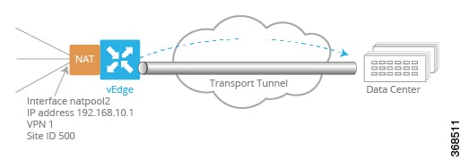
vEdge6(config)# vpn 1
vEdge6(config-vpn-1)# interface natpool2
vEdge6(config-natpool2)# ip address 10.16.1.4/30
vEdge6(config-natpool2)# no shutdown
vEdge6(config-natpool2)# nat
vEdge6(config-nat)# direction outside
vEdge6(config-nat)# static source-ip 10.15.1.4 translate-ip 10.16.1.4 outside
vEdge6(config-nat)# no overload

Here are the complete configurations for the static NAT pools on the vEdge5 and vEdge6 routers:

vEdge5# show running-config vpn 1 interface natpool1
vpn 1
 interface natpool1
  ip address 10.15.1.4/30
  nat
   static source-ip 10.20.24.17 translate-ip 10.15.1.4 inside
   static source-ip 10.20.25.18 translate-ip 10.25.1.1 outside
   no overload
  !
  no shutdown
 !
!
vEdge6# show running-config vpn 1 interface natpool2
vpn 1
 interface natpool2
  ip address 10.16.1.4/30
  nat
   static source-ip 10.15.1.4 translate-ip 10.16.1.4 outside
   direction outside
   no overload
  !
  no shutdown
 !
!

Configure Data Policies on vSmart Controllers

To direct service-side traffic to the NAT pool interface, you configure centralized data policies on the vSmart controllers. Our example network has two vSmart controllers, vSmart9 and vSmart10. The data policies must be identical on both of them.

The basic structure of the data policy is to define the match criteria for the packets destined to the NAT interface and then, in the action portion of the policy, to assign or direct the packets to a specific NAT pool. The data policy structure looks like this:

For a data-policy
  For a vpn-list
    For a sequence number
      Match specific criteria
      Action accept
        nat pool number
Apply the data-policy to all data traffic

In our example, we want a data policy that directs service-side traffic behind the vEdge5 router to the router's NAT pool interface 1 (interface natpool 1). Here is one portion of the data policy (specifically, one of the sequences within the policy) that does this, defining the service-side traffic by its source and destination IP addresses:

policy
  data-policy accept_nat
    vpn-list vpn_1
      sequence 108
        match
          source-ip      10.1.17.0/24
          destination-ip 10.25.1.0/24
        !
        action accept
          count nat_108
          nat pool 1
        !
      !
    !
  !
!
apply-policy
  site-list vedge1
    data-policy accept_nat all
  !
!

This data policy snippet takes data traffic whose source IP address is in the range 10.1.17.0/24 and destination is 10.25.1.0/24, accepts it, counts it to the file nat_108, and directs it to NAT pool 1. The source IP prefix 10.1.17.0/24 corresponds to traffic originating from Router7. The destination IP prefix 10.25.1.0/24 is an IP address that the vEdge5 router has translated from 10.20.25.18. This latter IP address corresponds to data traffic originating on Router8, so data traffic with a destination IP prefix of 10.25.1.0/24 is delivered to vEdge6 and then to Router8.

The second configuration snippet applies the policy to all traffic passing through the router (all).

Configure Route Redistribution by OSPF and BGP

By default, OSPF redistributes routes learned from inside NAT pool prefixes into OSPF. In addition, no routes from any other protocols are distributed into OSPF. The same is true for BGP.

In our configuration, we also want OSPF and BG to redistribute routes learned from outside NAT pool addresses. We also want OSPF to redistribute connected, OMP, and static routes, and we want BGP to redistribute OMP and static routes.

vEdge5# show running-config vpn 1 router
vpn 1
 router
  ospf
   redistribute static
   redistribute connected
   redistribute omp
   redistribute natpool-outside
   area 0
    interface ge0/4
     hello-interval 1
     dead-interval  3
    exit
   exit
  !
 !
!
vEdge6# show running-config vpn 1 router
vpn 1
 router
  bgp 1
   timers
    keepalive 1
    holdtime  3
   !
   address-family ipv4-unicast
    redistribute static
    redistribute omp
    redistribute natpool-outside
   !
   neighbor 10.20.25.18
    no shutdown
    remote-as 2
    timers
     connect-retry          2
     advertisement-interval 1
    !
   !
  !
 !
!

Verify the NAT Configuration

You use two commands to verify that the NAT configuration is operational: show interface and show ip nat interface.

The show interface command output indicates which NAT pool interfaces are configured and provides status about them. The command output for the vEdge5 router shows that NAT pool interface 1 is administratively and operational up. This command output also shows information about the other interfaces configured on vEdge 5.

vEdge5# show interface
                                        IF      IF                                                                TCP                                   
                AF                      ADMIN   OPER    ENCAP                                      SPEED          MSS                 RX       TX       
VPN  INTERFACE  TYPE  IP ADDRESS        STATUS  STATUS  TYPE   PORT TYPE  MTU   HWADDR             MBPS   DUPLEX  ADJUST  UPTIME      PACKETS  PACKETS  
--------------------------------------------------------------------------------------------------------------------------------------------------------
0    ge0/0      ipv4  10.1.15.15/24     Up      Up      null   transport  1500  00:0c:29:7d:1e:fe  1000   full    1420    0:09:52:43  226385   228332   
0    ge0/1      ipv4  10.1.17.15/24     Up      Up      null   service    1500  00:0c:29:7d:1e:08  1000   full    1420    0:07:00:23  1262     10       
0    ge0/2      ipv4  -                 Down    Down    null   service    1500  00:0c:29:7d:1e:12  -      -       1420    -           0        0        
0    ge0/3      ipv4  10.0.20.15/24     Up      Up      null   service    1500  00:0c:29:7d:1e:1c  1000   full    1420    0:07:00:23  1272     10       
0    ge0/6      ipv4  57.0.1.15/24      Up      Up      null   service    1500  00:0c:29:7d:1e:3a  1000   full    1420    0:07:00:22  1262     9        
0    ge0/7      ipv4  10.0.100.15/24    Up      Up      null   service    1500  00:0c:29:7d:1e:44  1000   full    1420    0:09:52:04  2931     741      
0    system     ipv4  172.16.255.15/32  Up      Up      null   loopback   1500  00:00:00:00:00:00  10     full    1420    0:06:59:24  0        0        
1    ge0/4      ipv4  10.20.24.15/24    Up      Up      null   service    1500  00:0c:29:7d:1e:26  1000   full    1420    0:07:00:19  26310    25065    
1    ge0/5      ipv4  56.0.1.15/24      Up      Up      null   service    1500  00:0c:29:7d:1e:30  1000   full    1420    0:07:00:19  1261     8        
1    natpool1   ipv4  -                 Up      Up      null   service    1500  00:00:00:00:00:00  10     full    1420    0:05:52:41  0        0        
1    natpool7   ipv4  -                 Up      Up      null   service    1500  00:00:00:00:00:00  10     full    1420    0:05:52:41  0        0        
1    natpool8   ipv4  -                 Up      Up      null   service    1500  00:00:00:00:00:00  10     full    1420    0:05:52:41  0        0        
1    natpool9   ipv4  -                 Up      Up      null   service    1500  00:00:00:00:00:00  10     full    1420    0:05:52:41  0        0        
1    natpool10  ipv4  -                 Up      Up      null   service    1500  00:00:00:00:00:00  10     full    1420    0:05:52:41  0        0        
1    natpool11  ipv4  -                 Up      Up      null   service    1500  00:00:00:00:00:00  10     full    1420    0:05:52:41  0        0        
1    natpool12  ipv4  -                 Up      Up      null   service    1500  00:00:00:00:00:00  10     full    1420    0:05:52:41  0        0        
1    natpool13  ipv4  -                 Up      Up      null   service    1500  00:00:00:00:00:00  10     full    1420    0:05:52:41  0        0        
1    natpool14  ipv4  -                 Up      Up      null   service    1500  00:00:00:00:00:00  10     full    1420    0:05:52:41  0        0        
1    natpool15  ipv4  -                 Up      Up      null   service    1500  00:00:00:00:00:00  10     full    1420    0:05:52:41  0        0        
1    natpool16  ipv4  -                 Up      Up      null   service    1500  00:00:00:00:00:00  10     full    1420    0:05:52:41  0        0        
512  eth0       ipv4  10.0.1.15/24      Up      Up      null   service    1500  00:50:56:00:01:0f  1000   full    0       0:09:52:42  19482    12745 

Similarly, on the vEdge6 router, we can check that its NAT pool 2 interface is up:

vEdge6# show interface
                                        IF      IF                                                                TCP                                   
                AF                      ADMIN   OPER    ENCAP                                      SPEED          MSS                 RX       TX       
VPN  INTERFACE  TYPE  IP ADDRESS        STATUS  STATUS  TYPE   PORT TYPE  MTU   HWADDR             MBPS   DUPLEX  ADJUST  UPTIME      PACKETS  PACKETS  
--------------------------------------------------------------------------------------------------------------------------------------------------------
0    ge0/0      ipv4  10.1.16.16/24     Up      Up      null   transport  1500  00:0c:29:d7:63:18  1000   full    1420    0:09:58:47  271786   294577   
0    ge0/1      ipv4  10.1.18.16/24     Up      Up      null   service    1500  00:0c:29:d7:63:22  1000   full    1420    0:07:06:18  1274     10       
0    ge0/2      ipv4  -                 Down    Down    null   service    1500  00:0c:29:d7:63:2c  -      -       1420    -           0        0        
0    ge0/3      ipv4  10.0.21.16/24     Up      Up      null   service    1500  00:0c:29:d7:63:36  1000   full    1420    0:07:06:18  1285     9        
0    ge0/7      ipv4  10.0.100.16/24    Up      Up      null   service    1500  00:0c:29:d7:63:5e  1000   full    1420    0:09:58:04  2971     746      
0    system     ipv4  172.16.255.16/32  Up      Up      null   loopback   1500  00:00:00:00:00:00  10     full    1420    0:07:05:28  0        0        
1    ge0/4      ipv4  10.20.25.16/24    Up      Up      null   service    1500  00:0c:29:d7:63:40  1000   full    1420    0:07:06:15  51457    50250    
1    ge0/5      ipv4  60.0.1.16/24      Up      Up      null   service    1500  00:0c:29:d7:63:4a  1000   full    1420    0:07:06:15  1273     8        
1    ge0/6      ipv4  61.0.1.16/24      Up      Up      null   service    1500  00:0c:29:d7:63:54  1000   full    1420    0:07:06:15  1255     8        
1    natpool2   ipv4  -                 Up      Up      null   service    1500  00:00:00:00:00:00  10     full    1420    0:05:56:37  0        0        
1    natpool12  ipv4  -                 Down    Down    null   service    1500  00:00:00:00:00:00  -      -       1420    -           0        0        
512  eth0       ipv4  10.0.1.16/24      Up      Up      null   service    1500  00:50:56:00:01:10  1000   full    0       0:09:58:39  17650    11555

To display information about the NAT pools themselves, use the show ip nat interface command. Here is the command output for the vEdge5 router in tabular format and for vEdge6 in nontabular format:

vEdge5# show ip nat interface
                                                                       FIB                     NUMBER  
                                                               FILTER  FILTER                  IP      
VPN  IFNAME     MAP TYPE              FILTER TYPE              COUNT   COUNT   IP              POOLS   
-------------------------------------------------------------------------------------------------------
1    natpool1   endpoint-independent  address-port-restricted  0       0       10.15.1.4/30    4       
1    natpool7   endpoint-independent  address-port-restricted  0       0       10.21.26.15/32  1       
1    natpool8   endpoint-independent  address-port-restricted  0       0       10.21.27.15/32  1       
1    natpool9   endpoint-independent  address-port-restricted  0       0       10.21.28.15/32  1       
1    natpool10  endpoint-independent  address-port-restricted  0       0       10.21.29.15/32  1       
1    natpool11  endpoint-independent  address-port-restricted  0       0       10.21.30.15/32  1       
1    natpool12  endpoint-independent  address-port-restricted  0       0       10.21.31.15/32  1       
1    natpool13  endpoint-independent  address-port-restricted  0       0       10.21.32.15/32  1       
1    natpool14  endpoint-independent  address-port-restricted  0       0       10.21.33.15/32  1       
1    natpool15  endpoint-independent  address-port-restricted  0       0       10.21.34.15/32  1       
1    natpool16  endpoint-independent  address-port-restricted  0       0       10.21.35.15/32  1
vEdge6# show ip nat interface
ip nat interface nat-vpn 1 nat-ifname natpool2
 mapping-type     endpoint-independent
 filter-type      address-port-restricted
 filter-count     0
 fib-filter-count 0
 ip               10.16.1.4/30

Verify Routes and Route Redistribution

We configured OSPF and BGP to redistributes routes learned from outside NAT into OSPF and BGP, respectively. (We also configured OSPF and BGP ro redistribute static and OMP routes, and we configured OMP to redistribute routes learned from directly connected devices.)

To see where routes have been learned from, look at the Protocol field in the output of the show ip routes command.

Looking on the vEdge5 router, we see that OSPF has redistributed 10.15.1.4/30, a route learned from an inside NAT (these routes are redistributed by default) and 10.25.1.1/32, a route learned from an outside NAT. The vEdge5 router translates the IP address 10.25.1.1 from 10.20.25.18. Both these routes have a next-hop interface of natpool1, which is the NAT pool we configured to run static NAT.

vEdge5# show ip routes
Codes Proto-sub-type:
  IA -> ospf-inter-area,
  E1 -> ospf-external1, E2 -> ospf-external2,
  N1 -> ospf-nssa-external1, N2 -> ospf-nssa-external2,
  e -> bgp-external, i -> bgp-internal
Codes Status flags:
  F -> fib, S -> selected, I -> inactive,
  B -> blackhole, R -> recursive

                                            PROTOCOL  NEXTHOP     NEXTHOP          NEXTHOP                                                   
VPN    PREFIX              PROTOCOL         SUB TYPE  IF NAME     ADDR             VPN      TLOC IP          COLOR            ENCAP  STATUS  
---------------------------------------------------------------------------------------------------------------------------------------------
0      0.0.0.0/0           static           -         ge0/0       10.1.15.13       -        -                -                -      F,S     
0      10.0.20.0/24        connected        -         ge0/3       -                -        -                -                -      F,S     
0      10.0.100.0/24       connected        -         ge0/7       -                -        -                -                -      F,S     
0      10.1.15.0/24        connected        -         ge0/0       -                -        -                -                -      F,S     
0      10.1.17.0/24        connected        -         ge0/1       -                -        -                -                -      F,S     
0      57.0.1.0/24         connected        -         ge0/6       -                -        -                -                -      F,S     
0      172.16.255.15/32    connected        -         system      -                -        -                -                -      F,S     
1      2.2.0.0/16          static           -         -           -                -        -                -                -      B,F,S   
1      4.4.4.4/32          static           -         -           -                -        -                -                -      B,F,S   
1      9.0.0.0/8           omp              -         -           -                -        172.16.255.16    lte              ipsec  F,S     
1      10.1.17.0/24        static           -         ge0/4       10.20.24.17      -        -                -                -      F,S     
1      10.1.18.0/24        omp              -         -           -                -        172.16.255.16    lte              ipsec  F,S     
1      10.2.2.0/24         omp              -         -           -                -        172.16.255.11    lte              ipsec  F,S     
1      10.2.3.0/24         omp              -         -           -                -        172.16.255.21    lte              ipsec  F,S     
1      10.15.1.4/30        natpool-inside   -         natpool1    -                -        -                -                -      F,S     
1      10.20.24.0/24       ospf             -         ge0/4       -                -        -                -                -      -       
1      10.20.24.0/24       connected        -         ge0/4       -                -        -                -                -      F,S     
1      10.20.25.0/24       omp              -         -           -                -        172.16.255.16    lte              ipsec  F,S     
1      10.25.1.0/24        static           -         -           -                -        -                -                -      B,F,S   
1      10.25.1.1/32        natpool-outside  -         natpool1    -                -        -                -                -      F,S     
1      56.0.1.0/24         connected        -         ge0/5       -                -        -                -                -      F,S     
1      60.0.1.0/24         omp              -         -           -                -        172.16.255.16    lte              ipsec  F,S     
1      61.0.1.0/24         omp              -         -           -                -        172.16.255.16    lte              ipsec  F,S     
512    10.0.1.0/24         connected        -         eth0        -                -        -                -                -      F,S

The vEdge6 router translates the outside source IP address 10.15.1.4 to 10.16.1.4. The route table on vEdge6 shows this route and that it has been learned from an outside NAT. The next-hop interface for this prefix is natpool2.

vEdge6# show ip routes
Codes Proto-sub-type:
  IA -> ospf-inter-area,
  E1 -> ospf-external1, E2 -> ospf-external2,
  N1 -> ospf-nssa-external1, N2 -> ospf-nssa-external2,
  e -> bgp-external, i -> bgp-internal
Codes Status flags:
  F -> fib, S -> selected, I -> inactive,
  B -> blackhole, R -> recursive

                                            PROTOCOL  NEXTHOP     NEXTHOP          NEXTHOP                                                   
VPN    PREFIX              PROTOCOL         SUB TYPE  IF NAME     ADDR             VPN      TLOC IP          COLOR            ENCAP  STATUS  
---------------------------------------------------------------------------------------------------------------------------------------------
0      0.0.0.0/0           static           -         ge0/0       10.1.16.13       -        -                -                -      F,S     
0      10.0.21.0/24        connected        -         ge0/3       -                -        -                -                -      F,S     
0      10.0.100.0/24       connected        -         ge0/7       -                -        -                -                -      F,S     
0      10.1.16.0/24        connected        -         ge0/0       -                -        -                -                -      F,S     
0      10.1.18.0/24        connected        -         ge0/1       -                -        -                -                -      F,S     
0      172.16.255.16/32    connected        -         system      -                -        -                -                -      F,S     
1      2.2.0.0/16          static           -         -           -                -        -                -                -      B,F,S   
1      4.4.4.4/32          omp              -         -           -                -        172.16.255.15    lte              ipsec  F,S     
1      9.0.0.0/8           static           -         -           -                -        -                -                -      B,F,S   
1      10.1.17.0/24        omp              -         -           -                -        172.16.255.15    lte              ipsec  F,S     
1      10.1.18.0/24        static           -         ge0/4       10.20.25.18      -        -                -                -      F,S     
1      10.2.2.0/24         omp              -         -           -                -        172.16.255.11    lte              ipsec  F,S     
1      10.2.3.0/24         omp              -         -           -                -        172.16.255.21    lte              ipsec  F,S     
1      10.15.1.4/30        omp              -         -           -                -        172.16.255.15    lte              ipsec  F,S     
1      10.16.1.4/30        natpool-outside  -         natpool2    -                -        -                -                -      F,S     
1      10.20.24.0/24       omp              -         -           -                -        172.16.255.15    lte              ipsec  F,S     
1      10.20.25.0/24       connected        -         ge0/4       -                -        -                -                -      F,S     
1      10.25.1.0/24        omp              -         -           -                -        172.16.255.15    lte              ipsec  F,S     
1      56.0.1.0/24         omp              -         -           -                -        172.16.255.15    lte              ipsec  F,S     
1      60.0.1.0/24         connected        -         ge0/5       -                -        -                -                -      F,S     
1      61.0.1.0/24         connected        -         ge0/6       -                -        -                -                -      F,S     
512    10.0.1.0/24         connected        -         eth0        -                -        -                -                -      F,S

View Interface Statistics

To display packet receipt and transmission statistics for the interfaces, use the show interface statistics command. The output shows the following statistics:

vEdge5# show interface statistics natpool1 | notab
interface vpn 1 interface natpool1 af-type ipv4
 rx-packets 0
 rx-octets  0
 rx-errors  0
 rx-drops   0
 tx-packets 0
 tx-octets  0
 tx-errors  0
 tx-drops   0
 rx-pps     0
 rx-kbps    0
 tx-pps     0
 tx-kbps    0

To display NAT-specific interface statistics, use the show ip nat interface-statistics command. The output shows the following statistics for each NAT pool:

vEdge5# show ip nat interface-statistics 
ip nat interface-statistics nat-vpn 1 nat-ifname natpool1
 nat-outbound-packets      0
 nat-inbound-packets       0
 nat-encode-fail           0
 nat-decode-fail           0
 nat-map-add-fail          0
 nat-filter-add-fail       0
 nat-filter-lookup-fail    0
 nat-state-check-fail      0
 nat-policer-drops         0
 outbound-icmp-error       0
 inbound-icmp-error        0
 inbound-icmp-error-drops  0
 nat-fragments             0
 nat-fragments-fail        0
 nat-unsupported-proto     0
 nat-map-no-ports          0
 nat-map-cannot-xlate      0
 nat-filter-map-mismatch   0
 nat-map-ip-pool-exhausted 0

View the Data Policy Pushed to the vEdge Routers

To view and verify the data policy pushed from the vSmart controllers to the two vEdge routers, use the show policy from-vsmart command. The following is the command output for the vEdge5 router. The output on vEdge6 is identical.

vEdge5# show policy from-vsmart
from-vsmart data-policy accept_nat
direction all
vpn-list vpn_1
  sequence 100
   match
    source-ip      10.20.24.0/24
    destination-ip 10.20.25.0/24
   action accept
    count nat
    nat pool 1
  sequence 101
   match
    source-ip      10.20.24.0/24
    destination-ip 10.1.15.13/32
   action accept
    count nat_inet
    nat use-vpn 0
  sequence 102
   match
    dscp 15
   action accept
    count nat_dscp
    nat use-vpn 0
  sequence 104
   match
    source-ip      10.1.18.0/24
    destination-ip 10.20.24.0/24
   action accept
    count nat2
    nat pool 1
  sequence 105
   match
    source-ip      10.1.18.0/24
    destination-ip 10.1.17.0/24
   action accept
    count nat3
    nat pool 1
  sequence 106
   match
    source-ip      10.1.17.0/24
    destination-ip 10.20.25.0/24
   action accept
    nat pool 1
  sequence 107
   match
    source-ip      10.15.1.0/24
    destination-ip 10.20.25.0/24
   action accept
    nat pool 2
  sequence 108
   match
    source-ip      10.1.17.0/24
    destination-ip 10.25.1.0/24
   action accept
    count nat_108
    nat pool 1
  sequence 109
   match
    source-ip      10.20.24.0/24
    destination-ip 10.25.1.0/24
   action accept
    count nat_109
    nat pool 1
  default-action accept
from-vsmart lists vpn-list vpn_1
vpn 1

Configurations for Each Network Device

For each of the network devices in this configuration example, this section shows the portions of the configuration relevant to the service-side NAT configuration.

vEdge5 Router

The vEdge5 router is located at site 500, has a system IP address of 172.16.255.15, and has one connection to the Internet:

system
 host-name         vm5
 system-ip         172.16.255.15
 site-id           500
!
vpn 0
 interface ge0/0
  ip address 10.1.15.15/24
  tunnel-interface
   encapsulation ipsec
   color lte
   hello-interval  60000
   hello-tolerance 120
   no allow-service bgp
   allow-service dhcp
   allow-service dhcpv6
   allow-service dns
   allow-service icmp
   no allow-service sshd
   no allow-service netconf
   no allow-service ntp
   no allow-service ospf
   no allow-service stun
  !
  no shutdown
 !
!

In VPN 1, NAT pool 1 runs 1:1 static NAT:

vpn 1
 interface natpool1
  ip address 10.15.1.4/30
  nat
   static source-ip 10.20.24.17 translate-ip 10.15.1.4 inside
   static source-ip 10.20.25.18 translate-ip 10.25.1.1 outside
   no overload
  !
  no shutdown
 !

VPN 1 also has a number of other NAT pool interfaces:

 interface natpool10
  ip address 10.21.29.15/32
  no shutdown
 !
 interface natpool11
  ip address 10.21.30.15/32
  no shutdown
 !
 interface natpool12
  ip address 10.21.31.15/32
  no shutdown
 !
 interface natpool13
  ip address 10.21.32.15/32
  no shutdown
 !
 interface natpool14
  ip address 10.21.33.15/32
  no shutdown
 !
 interface natpool15
  ip address 10.21.34.15/32
  no shutdown
 !
 interface natpool16
  ip address 10.21.35.15/32
  no shutdown
 !
 interface natpool7
  ip address 10.21.26.15/32
  no shutdown
 !
 interface natpool8
  ip address 10.21.27.15/32
  no shutdown
 !
 interface natpool9
  ip address 10.21.28.15/32
  no shutdown
 !
 ip route 2.2.0.0/16 null0
 ip route 4.4.4.4/32 null0
 ip route 10.1.17.0/24 10.20.24.17
 ip route 10.25.1.0/24 null0
!

OSPF runs in VPN 1 and is configured to redistribute routes learned from outside NAT prefixes into OSPF:

vpn 1
 router
  ospf
   timers spf 200 1000 10000
   redistribute static
   redistribute connected
   redistribute omp
   redistribute natpool-outside
   area 0
    interface ge0/4
     hello-interval 1
     dead-interval  3
    exit
   exit
  !
 !
!

vEdge6 Router

The vEdge6 router is located at site 600, has a system IP address of 172.16.255.16, and has one connection to the Internet:

system
 host-name         vm6
 system-ip         172.16.255.16
 site-id           600
!
vpn 0
 interface ge0/0
  ip address 10.1.16.16/24
  tunnel-interface
   encapsulation ipsec
   color lte
   no allow-service bgp
   allow-service dhcp
   allow-service dhcpv6
   allow-service dns
   allow-service icmp
   no allow-service sshd
   no allow-service netconf
   no allow-service ntp
   no allow-service ospf
   no allow-service stun
  !
  no shutdown
 !
!

VPN 1 has one NAT pool for static address translation:

vpn 1
 interface natpool12
  ip address 10.1.155.4/30
  shutdown
 !
 interface natpool2
  ip address 10.16.1.4/30
  nat
   static source-ip 10.15.1.4 translate-ip 10.16.1.4 outside
   direction outside
   no overload
  !
  no shutdown
 !
 ip route 2.2.0.0/16 null0
 ip route 9.0.0.0/8 null0
 ip route 10.1.18.0/24 10.20.25.18
!

BGP runs in VPN 1 and is configured to redistribute routes learned from outside NAT prefixes into BGP:

vm6# show running-config vpn 1 router
vpn 1
 router
  bgp 1
   timers
    keepalive 1
    holdtime  3
   !
   address-family ipv4-unicast
    redistribute static
    redistribute omp
    redistribute natpool-outside
   !
   neighbor 10.20.25.18
    no shutdown
    remote-as 2
    timers
     connect-retry          2
     advertisement-interval 1
    !
   !
  !
 !
! 

Router7 and Router8

Router7 sits in the local site behind the vEdge5 router, and it is an OSPF peer with vEdge5. Router8 sits behind the vEdge6 router and is an IBGP peer with vEdge6.

In our example network, both these routers are configured on vEdge software routers. However, there is nothing in their configuration that specifically relates to static NAT, so we do not show the configurations for these two devices.

vSmart9 and vSmart10 vSmart Controllers

You configure the data policy that runs on the vEdge routers to direct data traffic to the NAT interfaces on the vSmart controllers. The vSmart controllers then push the data policy to the appropriate vEdge routers. The configure data policy must be identical on all vSmart controllers in the overlay network to ensure reproducible data traffic handling in the network.

Here is the complete policy configuration for the two vSmart controllers in our example:

policy
 data-policy accept_nat
  vpn-list vpn_1
   sequence 100
    match
     source-ip      10.20.24.0/24
     destination-ip 10.20.25.0/24
    !
    action accept
     count nat
     nat pool 1
    !
   !
   sequence 101
    match
     source-ip      10.20.24.0/24
     destination-ip 10.1.15.13/32
    !
    action accept
     count nat_inet
     nat use-vpn 0
    !
   !
   sequence 102
    match
     dscp 15
    !
    action accept
     count nat_dscp
     nat use-vpn 0
    !
   !
   sequence 104
    match
     source-ip      10.1.18.0/24
     destination-ip 10.20.24.0/24
    !
    action accept
     count nat2
     nat pool 1
    !
   !
   sequence 105
    match
     source-ip      10.1.18.0/24
     destination-ip 10.1.17.0/24
    !
    action accept
     count nat3
     nat pool 1
    !
   !
   sequence 106
    match
     source-ip      10.1.17.0/24
     destination-ip 10.20.25.0/24
    !
    action accept
     nat pool 1
    !
   !
   sequence 107
    match
     source-ip      10.15.1.0/24
     destination-ip 10.20.25.0/24
    !
    action accept
     nat pool 2
    !
   !
   sequence 108
    match
     source-ip      10.1.17.0/24
     destination-ip 10.25.1.0/24
    !
    action accept
     count nat_108
     nat pool 1
    !
   !
      sequence 109
    match
     source-ip      10.20.24.0/24
     destination-ip 10.25.1.0/24
    !
    action accept
     count nat_109
     nat pool 1
    !
   !
   default-action accept
  !
 !
 lists
  vpn-list vpn_1
   vpn 1
  !
  site-list east
   site-id 100
   site-id 500
  !
  site-list vedge1
   site-id 500
  !
  site-list vedge2
   site-id 600
  !
  site-list vedges
   site-id 500
   site-id 600
  !
  site-list west
   site-id 200
   site-id 400
   site-id 600
  !
  prefix-list prefix_list
   ip-prefix 10.20.24.0/24
  !
 !
!
vm9# show running-config apply-policy 
apply-policy
 site-list vedge1
  data-policy accept_nat all
 !
 site-list vedge2
  data-policy accept_nat all
 !
!