Control Policy

Control policy, which is similar to standard routing policy, operates on routes and routing information in the control plane of the overlay network. Centralized control policy, which is provisioned on the Cisco SD-WAN Controller, is the Cisco Catalyst SD-WAN technique for customizing network-wide routing decisions that determine or influence routing paths through the overlay network. Local control policy, which is provisioned on a Cisco vEdge device, allows customization of routing decisions made by BGP and OSPF on site-local branch or enterprise networks.

The routing information that forms the basis of centralized control policy is carried in Cisco Catalyst SD-WAN route advertisements, which are transmitted on the DTLS or TLS control connections between Cisco SD-WAN Controllers and Cisco vEdge devices. Centralized control policy determines which routes and route information are placed into the centralized route table on the Cisco SD-WAN Controller and which routes and route information are advertised to the Cisco vEdge devices in the overlay network. Basic centralized control policy establish traffic engineering, to set the path that traffic takes through the network. Advanced control policy supports a number of features, including service chaining, which allows Cisco vEdge devices in the overlay network to share network services, such as firewalls and load balancers.

Centralized control policy affects the OMP routes that are distributed by the Cisco SD-WAN Controller throughout the overlay network. The Cisco SD-WAN Controller learns the overlay network topology from OMP routes that are advertised by the Cisco vEdge devices over the OMP sessions inside the DTLS or TLS connections between the Cisco SD-WAN Controller and the devices.

Three types of OMP routes carry the information that the Cisco SD-WAN Controller uses to determine the network topology:

  • Cisco Catalyst SD-WAN OMP routes, which are similar to IP route advertisements, advertise routing information that the devices have learned from their local site and the local routing protocols (BGP and OSPF) to the Cisco SD-WAN Controller. These routes are also referred to as OMP routes or Routes.

  • TLOC routes carry overlay network–specific locator properties, including the IP address of the interface that connects to the transport network, a link color, which identifies a traffic flow, and the encapsulation type. (A TLOC, or transport location, is the physical location where a Cisco vEdge device connects to a transport network. It is identified primarily by IP address, link color, and encapsulation, but a number of other properties are associated with a TLOC.)

  • Service routes advertise the network services, such as firewalls, available to VPN members at the local site.

Figure 1. Control Policy Topology

By default, no centralized control policy is provisioned. In this bare, unpolicied network, all OMP routes are placed in the Cisco SD-WAN Controller's route table as is, and the Cisco SD-WAN Controller advertises all OMP routes, as is, to all the devices in the same VPN in the network domain.

By provisioning centralized control policy, you can affect which OMP routes are placed in the Cisco SD-WAN Controller's route table, what route information is advertised to the devices, and whether the OMP routes are modified before being put into the route table or before being advertised.

Cisco vEdge devices place all the route information learned from the Cisco SD-WAN Controllers, as is, into their local route tables, for use when forwarding data traffic. Because the Cisco SD-WAN Controller's role is to be the centralized routing system in the network, Cisco vEdge devices can never modify the OMP route information that they learn from the Cisco SD-WAN Controllers.

The Cisco SD-WAN Controller regularly receives OMP route advertisements from the devices and, after recalculating and updating the routing paths through the overlay network, it advertises new routing information to the devices.

The centralized control policy that you provision on the Cisco SD-WAN Controller remains on the Cisco SD-WAN Controller and is never downloaded to the devices. However, the routing decisions that result from centralized control policy are passed to the devices in the form of route advertisements, and so the affect of the control policy is reflected in how the devices direct data traffic to its destination.

A type of centralized control policy called service chaining allows data traffic to be routed through one or more network services, such as firewall, load balancer, and intrusion detection and prevention (IDP) devices, en route to its destination.

Localized control policy, which is provisioned locally on the devices, is called route policy. This policy is similar to the routing policies that you configure on a regular driver, allowing you to modify the BGP and OSPF routing behavior on the site-local network. Whereas centralized control policy affects the routing behavior across the entire overlay network, route policy applies only to routing at the local branch.

The Cisco Catalyst SD-WAN devices periodically exchange OMP updates, which carry routing information pertaining to the overlay network. Two of the things that these updates contain are Route attributes and Transport Locations (TLOC) attributes.

The Cisco SD-WAN Controller uses these attributes from the OMP updates to determine the topology and status of the overlay network, and installs routing information about the overlay network into its route table. The controller then advertises the overlay topology to the Cisco vEdge devices in the network by sending OMP updates to them.

Control policy examines the Route and TLOC attributes carried in OMP updates and can modify attributes that match the policy. Any changes that results from control policy are applied directionally, either inbound or outbound.

The figure shows a control-policy named prefer_local that is configured on a Cisco SD-WAN Controller and that is applied to Site 1 (via site-list list1) and to Site 2 (via site-list list2).

Figure 2. Control Policy Topology
Device# apply-policy
site-list list1
control-policy prefer_local in
!

The upper left arrow shows that the policy is applied to Site 1—more specifically, to site-list list1, which contains an entry for Site 1. The command control-policy prefer_local in is used to apply the policy to OMP updates that are coming in to the Cisco SD-WAN Controller from the Cisco vEdge device, which is inbound from the perspective of the controller. The in keyword indicates an inbound policy. So, for all OMP updates that the Site 1 devices send to the Cisco SD-WAN Controller, the "prefer_local" control policy is applied before the updates reach the route table on the Cisco SD-WAN Controller. If any Route or TLOC attributes in an OMP update match the policy, any changes that result from the policy actions occur before the Cisco SD-WAN Controller installs the OMP update information into its route table.

The route table on the Cisco SD-WAN Controller is used to determine the topology of the overlay network. The Cisco SD-WAN Controller then distributes this topology information, again via OMP updates, to all the devices in the network. Because applying policy in the inbound direction influences the information available to the Cisco SD-WAN Controller. It determines the network topology and network reachablity, modifying Route and TLOC attributes before they are placed in the controller’s route table.

apply-policy
site-list list2
control-policy prefer_local out
!

On the right side of the figure above, the "prefer_local" policy is applied to Site 2 via the control-policy prefer_local out command. The out keyword in the command indicates an outbound policy, which means that the policy is applied to OMP updates that the Cisco SD-WAN Controller is sending to the devices at Site 2. Any changes that result from the policy occur, after the information from the Cisco SD-WAN Controller's route table is placed in to an OMP update and before the devices receive the update. Again, note that the direction is outbound from the perpspective of the Cisco SD-WAN Controller.

In contrast to an inbound policy, which affects the centralized route table on the Cisco SD-WAN Controller and has a broad effect on the route attributes advertised to all the devices in the overlay network. A control policy applied in the outbound direction influences only the route tables on the individual devices included in the site-list.

The same control policy (the prefer_local policy) is applied to both the inbound and outbound OMP updates. However, the effects of applying the same policy to inbound and outbound are different. The usage shown in the figure illustrates the flexibility of the Cisco Catalyst SD-WAN control policy design architecture and configuration.

Centralized Control Policy Architecture

In the Cisco Catalyst SD-WAN network architecture, centralized control policy is handled by the Cisco SD-WAN Controller, which effectively is the routing engine of the network. The Cisco SD-WAN Controller is the centralized manager of network-wide routes, maintaining a primary route table for these routes. The Cisco SD-WAN Controller builds its route table based on the route information advertised by the Cisco vEdge devices in its domain, using these routes to discover the network topology and to determine the best paths to network destinations. The Cisco SD-WAN Controller distributes route information from its route table to the devices in its domain which in turn use these routes to forward data traffic through the network. The result of this architecture is that networking-wide routing decisions and routing policy are orchestrated by a central authority instead of being implemented hop by hop, by the devices in the network.

Centralized control policy allows you to influence the network routes advertised by the Cisco SD-WAN Controllers. This type of policy, which is provisioned centrally on the Cisco SD-WAN Controller, affects both the route information that the Cisco SD-WAN Controller stores in its primary route table and the route information that it distributes to the devices.

Centralized control policy is provisioned and applied only on the Cisco SD-WAN Controller. The control policy configuration itself is never pushed to devices in the overlay network. What is pushed to the devices, using the Overlay Management Protocol (OMP), are the results of the control policy, which the devices then install in their local route tables and use for forwarding data traffic. This design means that the distribution of network-wide routes is always administered centrally, using policies designed by network administrators. These policies are always implemented by centralized Cisco SD-WAN Controllers, which are responsible for orchestrating the routing decisions in the Cisco Catalyst SD-WAN overlay network.

Within a network domain, the network topology map on all Cisco SD-WAN Controllers must be synchronized. To support this, you must configure identical policies on all the Cisco SD-WAN Controllers in the domain.
Figure 3. Centralized Control Policy

All centralized control plane traffic, including route information, is carried by OMP peering sessions that run within the secure, permanent DTLS connections between devices and the Cisco SD-WAN Controllers in their domain. The end points of an OMP peering session are identified by the system IDs of the devices, and the peering sessions carry the site ID, which identifies the site in which the device is located. A DTLS connection and the OMP session running over it remain active as long as the two peers are operational.

Control policy can be applied both inbound, to the route advertisements that the Cisco SD-WAN Controller receives from the devices, and outbound, to advertisements that it sends to them. Inbound policy controls which routes and route information are installed in the local routing database on the Cisco SD-WAN Controller, and whether this information is installed as-is or is modified. Outbound control policy is applied after a route is retrieved from the routing database, but before a Cisco SD-WAN Controller advertises it, and affects whether the route information is advertised as-is or is modified.

Route Types

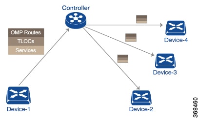
The Cisco SD-WAN Controller learns the network topology from OMP routes, which are Cisco Catalyst SD-WAN-specific routes carried by OMP. There are three types of OMP routes:

  • Cisco Catalyst SD-WAN OMP routes—These routes carry prefix information that the devices learn from the routing protocols running on its local network, including routes learned from BGP and OSPF, as well as direct, connected, and static routes. OMP advertises OMP routes to the Cisco SD-WAN Controller by means of an OMP route SAFI (Subsequent Address Family Identifier). These routes are commonly simply called OMP routes.

  • TLOC routes—These routes carry properties associated with transport locations, which are the physical points at which the devices connect to the WAN or the transport network. Properties that identify a TLOC include the IP address of the WAN interface and a color that identifies a particular traffic flow. OMP advertises TLOC routes using a TLOC SAFI.

  • Service routes—These routes identify network services, such as firewalls and IDPs, that are available on the local-site network to which the devices are connected. OMP advertises these routes using a service SAFI.

Default Behavior Without Centralized Control Policy

By default, no centralized control policy is provisioned on the Cisco SD-WAN Controller. This results in the following route advertisement and redistribution behavior within a domain:

  • All Cisco vEdge devices redistribute all the route-related prefixes that they learn from their site-local network to the Cisco SD-WAN Controller. This route information is carried by OMP route advertisements that are sent over the DTLS connection between the devices and the Cisco SD-WAN Controller. If a domain contains multiple Cisco SD-WAN Controllers, the devices send all OMP route advertisements to all the controllers.

  • All the devices send all TLOC routes to the Cisco SD-WAN Controller or controllers in their domain, using OMP.

  • All the devices send all service routes to advertise any network services, such as firewalls and IDPs, that are available at the local site where the device is located. Again, these are carried by OMP.

  • The Cisco SD-WAN Controller accepts all the OMP, TLOC, and service routes that it receives from all the devices in its domain, storing the information in its route table. The Cisco SD-WAN Controller tracks which OMP routes, TLOCs, and services belong to which VPNs. The Cisco SD-WAN Controller uses all the routes to develop a topology map of the network and to determine routing paths for data traffic through the overlay network.

  • The Cisco SD-WAN Controller redistributes all information learned from the OMP, TLOC, and service routes in a particular VPN to all the devices in the same VPN.

  • The devices regularly send route updates to the Cisco SD-WAN Controller.

  • The Cisco SD-WAN Controller recalculates routing paths, updates its route table, and advertises new and changed routing information to all the devices.

Behavior Changes with Centralized Control Policy

When you do not want to redistribute all route information to all Cisco vEdge devices in a domain, or when you want to modify the route information that is stored in the Cisco Catalyst SD-WAN Controller's route table or that is advertised by the Cisco Catalyst SD-WAN Controller, you design and provision a centralized control policy. To activate the control policy, you apply it to specific sites in the overlay network in either the inbound or the outbound direction. The direction is with respect to the Cisco Catalyst SD-WAN Controller. All provisioning of centralized control policy is done on the Cisco Catalyst SD-WAN Controller.

Applying a centralized control policy in the inbound direction filters or modifies the routes being advertised by the Cisco vEdge device before they are placed in the route table on the Cisco Catalyst SD-WAN Controller. As the first step in the process, routes are either accepted or rejected. Accepted routes are installed in the route table on the Cisco Catalyst SD-WAN Controller either as received or as modified by the control policy. Routes that are rejected by a control policy are silently discarded.​

Applying a control policy in outbound direction filters or modifies the routes that the Cisco Catalyst SD-WAN Controller redistributes to the Cisco vEdge devices. As the first step of an outbound policy, routes are either accepted or rejected. For accepted routes, centralized control policy can modify the routes before they are distributed by the Cisco Catalyst SD-WAN Controller. Routes that are rejected by an outbound policy are not advertised.

VPN Membership Policy

A second type of centralized data policy is VPN membership policy. It controls whether a Cisco vEdge device can participate in a particular VPN. VPN membership policy defines which VPNs of a device is allowed and which is not allowed to receive routes from.

VPN membership policy can be centralized, because it affects only the packet headers and has no impact on the choice of interface that a Cisco vEdge device uses to transmit traffic. What happens instead is that if, because of a VPN membership policy, a device is not allowed to receive routes for a particular VPN, the Cisco Catalyst SD-WAN Controller never forwards those routes to that driver.

Examples of Modifying Traffic Flow with Centralized Control Policy

This section provides some basic examples of how you can use centralized control policies to modify the flow of data traffic through the overlay network.

Create an Arbitrary Topology

When data traffic is exchanged between two Cisco vEdge devices, if you have provisioned no control policy, the two devices establish an IPsec tunnel between them and the data traffic flows directly from one device to the next. For a network with only two devices or with just a small number of devices, establishing connections between each pair of devices is generally not been an issue. However, such a solution does not scale. In a network with hundreds or even thousands of branches, establishing a full mesh of IPsec tunnels tax the CPU resources of each device.
Figure 4. Arbitrary Topology

One way to minimize this overhead is to create a hub-and-spoke type of topology in which one of the devices acts as a hub site that receives the data traffic from all the spoke, or branch, devices and then redirects the traffic to the proper destination. This example shows one of the ways to create such a hub-and-spoke topology, which is to create a control policy that changes the address of the TLOC associated with the destination.

The figure illustrates how such a policy might work. The topology has two branch locations, West and East. When no control policy is provisioned, these two devices exchange data traffic with each other directly by creating an IPsec tunnel between them (shown by the red line). Here, the route table on the Device West contains a route to Device East with a destination TLOC of 203.0.113.1, color gold (which we write as the tuple {192.0.2.1, gold}), and Device East route table has a route to the West branch with a destination TLOC of {203.0.113.1, gold}.

To set up a hub-and-spoke–​type topology here, we provision a control policy that causes the West and East devices to send all data packets destined for the other device to the hub device. (Remember that because control policy is always centralized, you provision it on the Cisco Catalyst SD-WAN Controller.) On the Device West, the policy simply changes the destination TLOC from {203.0.113.1, gold} to {209.165.200.225, gold}, which is the TLOC of the hub device, and on the Device East, the policy changes the destination TLOC from {192.0.2.1, gold} to the hub's TLOC, {209.165.200.225, gold}. If there were other branch sites on the west and east sides of the network that exchange data traffic, you could apply these same two control policies to have them redirect all their data traffic through the hub.

Set Up Traffic Engineering

Control policy allows you to design and provision traffic engineering. In a simple case, suppose that you have two devices acting as hub devices. If you want data traffic destined to a branch Cisco vEdge device to always transit through one of the hub devices, set the TLOC preference value to favor the desired hub device.
Figure 5. Traffic Engineering Topology

The figure shows that Site ID 100 has two hub devices, one that serves the West side of the network and a second that serves the East side. Data traffic from the Device West must be handled by the Device West hub, and similarly, data traffic from the Device East branch must go through the Device East hub.

To engineer this traffic flow, you provision two control policies, one for Site ID 1, where the Device West device is located, and a second one for Site ID 2. The control policy for Site ID 1 changes the TLOC for traffic destined to the Device East to {209.165.200.225, gold}, and the control policy for Site ID 2 changes the TLOC for traffic destined for Site ID 1 to {198.51.100.1, gold}. One additional effect of this traffic engineering policy is that it load-balances the traffic traveling through the two hub devices.

With such a traffic engineering policy, a route from the source device to the destination device is installed in the local route table, and traffic is sent to the destination regardless of whether the path between the source and destination devices is available. Enabling end-to-end tracking of the path to the ultimate destination allows the Cisco Catalyst SD-WAN Controller to monitor the path from the source to the destination, and to inform the source device when that path is not available. The source device can then modify or remove the path from its route table.

Figure 6. Traffic Engineering 2
The figure Traffic Engineering 2 illustrates end-to-end path tracking. It shows that traffic from Device-A that is destined for Device-D first goes to an intermediate device, Device-B, perhaps because this intermediate device provides a service, such as a firewall. (You configure this traffic engineering with a centralized control policy that is applied to Device-A, at Site 1.) Then Device-B, which has a direct path to the ultimate destination, forwards the traffic to Device-D. So, in this example, the end-to-end path between Device-A and Device-D comprises two tunnels, one between Device-A and Device-B, and the second between Device-B and Device-D. The Cisco Catalyst SD-WAN Controller tracks this end-to-end path, and it notifies Device-A if the portion of the path between Device-B and Device-D becomes unavailable.

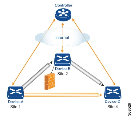
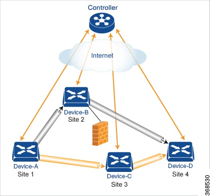
As part of end-to-end path tracking, you can specify how to forwarded traffic from the source to the ultimate destination using an intermediate device. The default method is strict forwarding, where traffic is always sent from Device-A to Device-B, regardless of whether Device-B has a direct path to Device-D or whether the tunnel between Device-B and Device-D is up. More flexible methods forward some or all traffic directly from Device-A to Device-D. You can also set up a second intermediate device to provide a redundant path with the first intermediate device is unreachable and use an ECMP method to forward traffic between the two. The figure Traffic Engineering3 adds Device-C as a redundant intermediate device.

Figure 7. Traffic Engineering 3

Centralized control policy, which you configure on Cisco Catalyst SD-WAN Controllers, affects routing policy based on information in OMP routes and OMP TLOCs.

This type of policy allows you to set actions for matching routes and TLOCs, including redirecting packets through network services, such as firewalls, a feature that is called service chaining.

In domains with multiple Cisco Catalyst SD-WAN Controllers, all the controllers must have the same centralized control policy configuration to ensure that routing within the overlay network remains stable and predictable.

Configure the Network Topology

When you first open the Configure Topology and VPN Membership screen, the Topology tab is selected by default.

To configure the network topology and VPN membership, see the following sections.

Configuration Components

A centralized control policy consists of a series of numbered (ordered) sequences of match-action pairs that are evaluated in order, from lowest sequence number to highest sequence number. When a route or TLOC matches the match conditions, the associated action or actions are taken and policy evaluation on that packets stops. Keep this process in mind as you design your policies to ensure that the desired actions are taken on the items subject to policy.

If a route or TLOC matches no parameters in any of the sequences in the policy configure, it is, by default, rejected and discarded.

The figure illustrates the configuration components for a centralized control policy.

Create a Hub and Spoke Policy

Procedure

Step 1

In the Add Topology drop-down, select Hub and Spoke.

Step 2

Enter a name for the hub-and-spoke policy.

Step 3

Enter a description for the policy.

Step 4

In the VPN List field, select the VPN list for the policy.

Step 5

In the left pane, click Add Hub and Spoke. A hub-and-spoke policy component containing the text string My Hub-and-Spoke is added in the left pane.

Step 6

Double-click the My Hub-and-Spoke text string, and enter a name for the policy component.

Step 7

In the right pane, add hub sites to the network topology:

  1. Click Add Hub Sites.

  2. In the Site List Field, select a site list for the policy component.

  3. Click Add.

  4. Repeat these steps to add more hub sites to the policy component.

Step 8

In the right pane, add spoke sites to the network topology:

  1. Click Add Spoke Sites.

  2. In the Site List Field, select a site list for the policy component.

  3. Click Add.

  4. Repeat these steps to add more spoke sites to the policy component.

Step 9

Repeat steps as needed to add more components to the hub-and-spoke policy.

Step 10

Click Save Hub and Spoke Policy.


Create a Policy for Mesh

Procedure

Step 1

In the Add Topology drop-down, select Mesh.

Step 2

Enter a name for the mesh region policy component.

Step 3

Enter a description for the mesh region policy component.

Step 4

In the VPN List field, select the VPN list for the policy.

Step 5

Click New Mesh Region.

Step 6

In the Mesh Region Name field, enter a name for the individual mesh region.

Step 7

In the Site List field, select one or more sites to include in the mesh region.

Step 8

Repeat these steps to add more mesh regions to the policy.

Step 9

Click Save Mesh Region.


Custom Control (Route and TLOC)

Policy for a topology with a custom route and TLOC configuration.

Procedure

Step 1

In the Add Topology drop-down, select Custom Control (Route & TLOC).

Step 2

Enter a name for the custom control policy component.

Step 3

Enter a description of the custom control policy component.

Step 4

Click Sequence Type. The Add Control Policy popup displays.

Step 5

Click Route or TLOC to create a policy of that type.

Step 6

Click Sequence Rule.


Custom Control (Route)

Create a policy to apply on an OMP route. By default, the Match tab is selected, displaying match condition options.

Procedure

Step 1

From the Add Custom Control Policy screen, click Route.

Step 2

Click Sequence Rule. Match and Actions options display.

Step 3

From the Match tab, select and configure match conditions for your route.

Match Condition

Description

Color List

Select a color list to match, or click New Color List to create a new list:

  1. Enter a name for the Color list.

  2. From the Select Color drop-down menu, select the color(s) you want included in your list.

  3. Click Save.

OMP Tag

Enter the OMP route tag, a number between 0-4294967295.

Origin

Select an origin for the route from the drop-down menu. Options include:
  • Aggregate

  • BGP External

  • BGP Internal

  • Connected

  • OSPF

  • OSPF External 1

  • OSPF External 2

  • OSPF Intra-Area

  • Static.

Originator

Enter the IP address of the originator of this route.

Preference

Enter the preference number for the route, a number between 0-4294967295.

Site

Select a site list from the list of options, or create a new site list:

  1. Enter a name for the Site list.

  2. Enter the Site numbers, following the example.

  3. Click Save.

TLOC

Select a TLOC list to match, or create a new TLOC list:

  1. Enter a name for the TLOC list.

  2. In the TLOC IP field, enter the IP address for the TLOC.

  3. In the Color drop-down menu, select the color you want to apply to the TLOC list.

  4. From the Encap drop-down menu, select the encapsulation type for the TLOC list.

  5. In the Preference field, enter the preference number for the route, a number between 0-4294967295.

  6. Optionally, click Add TLOC and repeat steps 1-5 to open another TLOC list.

  7. Click Save.

VPN

  1. From the Match Conditions > VPN list field, select a VPN list, or click New VPN List to create a new one:

  2. Enter a name for the VPN List.

  3. In the VPN field, enter the VPN numbers, for example, 100 or 200 separated by commas, or 1000-2000 by range.

  4. Click Save.

Prefix List

From the Match Conditions > Prefix List field, select a Prefix list, or click New Prefix List to create a new one:

  1. From the Prefix List drop-down menu, select a prefix list, or create a new one.

  2. In the Add Prefix field, enter the IP prefixes, or click Import on the right to import prefixes.

  3. Click Save.

Note


The Prefix List option is not available if you select protocol Both (IPv4 and IPv6).

Step 4

From the Actions tab, select IPv4, IPv6, or Both, to designate which protocol the actions should apply to. Not all of the following options are available for all protocols.

Step 5

Click Accept or Reject for the IP traffic meeting the match conditions.

Match Condition

Description

Accept

Allow traffic from the selected protocol. Click the following menu buttons to open configuration fields:

Export To—Select a VPN list, or create a new one.

OMP Tag—Enter the OMP route tag, a number between 0-4294967295.

Preference—Enter the preference number for the route, a number between 0-4294967295.

Service— Enter the following information:

Type—Select a service type. Options are:

  • Firewall

  • Intrusion Detection Prevention

  • Intrusion Detection System

  • Net Service 1

  • Net Service 2

  • Net Service 3

  • Net Service 4

  • Net Service 5

VPN—Enter the number of the Service VPN.

TLOC IP—Enter the IP address of the Service TLOC.

Color—Select a Color type from the drop-down list.

Encapsulation—Select IPSEC or GRE as the encapsulation type.

TLOC List—Select a service TLOC list from the drop-down menu, or create a new one.

TLOC Action

Select an action from the drop-down menu:
  • Strict—Direct matching traffic only to the intermediate destination. With this action, if the intermediate destination is down, no traffic reaches the final destination. If you do not configure a set tloc-action action in a centralized control policy, strict is the default behavior.

  • Primary—First direct matching traffic to the intermediate destination. If that driver is not reachable, then direct it to the final destination. With this action, if the intermediate destination is down, all traffic reaches the final destination.

  • Backup—First direct matching traffic to the final destination. If that driver is not reachable, then direct it to the intermediate destination. With this action, if the source is unable to reach the final destination directly, it is possible for all traffic to reach the final destination via the intermediate destination.

  • Equal Cost Multi-path—Equally direct matching control traffic between the intermediate destination and the ultimate destination. With this action, if the intermediate destination is down, all traffic reaches the ultimate destination.

TLOC—Enter the following information:
  • TLOC List—Select a TLOC list, or create a new one.

  • TLOC IP—Enter the IP address of the designated TLOC.

  • Color—Select a color from the available options.

Encapsulation—Select IPSEC or GRE as the encapsulation type.
Reject

Reject traffic for the selected conditions.

  1. Select a protocol from the Protocol dropdown: IPv4, IPv6, or Both.

  2. Click Accept or Reject for the match conditions.

  3. Optionally, repeat these steps with a different protocol.

Step 6

Click Save Match and Actions.


Create a Custom Control (TLOC)

Create a policy to apply to a TLOC. By default, the Match tab is selected, displaying match condition options.

Procedure

Step 1

From the Add Custom Control Policy screen, click TLOC.

Step 2

Click Sequence Rule. Match and Actions options display.

Step 3

From the Match tab, select and configure match conditions for your route.

Match Condition

Description

Carrier

Select a carrier from the drop-down list.

Color List

Select a color list from the drop-down list, or create a new one.

Domain ID

Enter a domain ID number, between 1-4294967295.

Group ID

Enter a Group ID number, between 1-4294967295.

OMP Tag

Enter an OMP tag number, between 1-4294967295.

Originator

Enter the IP address of the originator of the TLOC.

Preference

Enter a preference number for the policy, between 1-4294967295.

Site List

Select a site list from the drop-down list, create a new one, or enter a site ID in the Site ID field, between 1-4294967295.

TLOC

Select a TLOC from the drop-down list, or create a new one or Select a TLOC from the drop-down list, or create a new one.

Enter the following values:

  • TLOC IP—Enter the IP address of the TLOC.

  • Color—Select a color list from the available options.

  • Encapsulation—Select IPSEC or GRE as the encapsulation type.

Step 4

Click Accept or Reject to apply the following match conditions to an action.

Action Condition

Description

Accept

Allow traffic from the selected protocol. Click the following menu buttons to open configuration fields:

  • OMP Tag—Enter an OMP tag number, between 1-4294967295.

  • Preference—Enter a preference number for the policy, between 1-4294967295.

Reject

Reject traffic for the selected conditions.


Import Existing Topology

Procedure

Step 1

In the Add Topology drop-down, select Import Existing Topology to open the matching popup

Step 2

Under Policy Type, click the topology type you want to import:

  1. Hub and Spoke

  2. Mesh

  3. Custom

Step 3

Select a policy from the field list. Cisco SD-WAN Manager populates this field from the available topologies for the type you select.

Step 4

Click Import.

Step 5

Click Save Control Policy to save the Route policy.


Create a VPN Membership Policy

Procedure

Step 1

In the Topology bar, click VPN Membership.

Step 2

Click Add VPN Membership Policy. The Update VPN Membership Policy popup displays.

Step 3

Enter a name and description for the VPN membership policy.

Step 4

In the Site List field, select the site list.

Step 5

In the VPN Lists field, select the VPN list.

Step 6

Click Add List to add another VPN to the VPN membership.

Step 7

Click Save.

Step 8

Click Next to move to Configure Traffic Rules in the wizard.


Configure Centralized Policies Using Cisco SD-WAN Manager

To configure a centralized policy, use the Cisco SD-WAN Manager policy configuration wizard. The wizard consists of the following operations that guide you through the process of creating and editing policy components:

  • Create Groups of Interest: Create lists that group together related items and that you call in the match or action components of a policy.

  • Configure Topology and VPN Membership: Create the network structure to which the policy applies.

  • Configure Traffic Rules: Create the match and action conditions of a policy.

  • Apply Policies to Sites and VPNs: Associate the policy with sites and VPNs in the overlay network.

  • Activate the centralized policy.

    For a centralized policy to take effect, you must activate the policy.

To configure centralized policies using Cisco SD-WAN Manager, use the steps identified in the procedures that follow this section.

Components of Centralized Policies

The following are the components required to configure a centralized policy. Each one is explained in more detail in the sections below.

policy lists color-list list-name color color prefix-list list-name ip-prefix prefix 
site-list list-name site-id site-id tloc-list list-name tloc address color color 
encap encapsulation [preference value] vpn-list list-name vpn vpn-id
control-policy policy-name
sequence number
match match-parameters
action reject accept export-to vpn accept set parameter
default-action (accept | reject) apply-policy site-list list-name control-policy policy-name (in | out)

Components for VPN Membership

The following are the components required to configure a VPN membership policy. Each one is explained in more detail in the sections that follow.

policy
  lists
    app-list list-name
      (app applications | app-family application-families)
    data-prefix-list list-name 
      ip-prefix prefix 
    site-list list-name 
      site-id site-id 
    tloc-list list-name
      tloc ip-address color color encap encapsulation [preference value]
    vpn-list list-name 
      vpn vpn-id 
  policer policer-name
    burst bytes
    exceed action
    rate bandwidth
  data-policy policy-name 
    vpn-list list-name 
      sequence number 
        match
          app-list list-name
          destination-data-prefix-list list-name
          destination-ip prefix/length
          destination-port port-numbers
          dscp number
          dns-app-list list-name
          dns (request | response)
          packet-length number
          protocol number
          icmp-msg
          icmp6-msg
          source-data-prefix-list list-name
          source-ip prefix/length
          source-port port-numbers
          tcp flag
        action
          cflowd (not available for deep packet inspection)
          count counter-name
          drop
          log
          redirect-dns (dns-ip-address | host)
          tcp-optimization
          accept
            nat [pool number] [use-vpn 0]
            set 
              dscp number
              forwarding-class class
              local-tloc color color [encap encapsulation] [restrict]
              next-hop ip-address
              policer policer-name
              service service-name local [restrict] [vpn vpn-id]
              service service-name [tloc ip-address | tloc-list list-name] [vpn vpn-id]
              tloc ip-address color color [encap encapsulation]
              tloc-list list-name
              vpn vpn-id
      default-action
        (accept | drop)
apply-policy site-list list-name 
  data-policy policy-name (all | from-service | from-tunnel)

Apply Centralized Control Policy in the CLI

You apply centralized control policy directionally:

  • Inbound direction (in )—The policy analyzes routes and TLOCs being received from the sites in the site list before placing the routes and TLOCs into the route table on the Cisco Catalyst SD-WAN Controller, so the specified policy actions affect the OMP routes stored in the route table.

  • Outbound direction (out )—The policy analyzes routes and TLOCs in the Cisco Catalyst SD-WAN Controller's route table after they are exported from the route table.

For all control-policy policies that you apply with apply-policy commands, the site IDs across all the site lists must be unique. That is, the site lists must not contain overlapping site IDs. An example of overlapping site IDs are those in the two site lists site-list 1 site-id 1-100 and site-list 2 site-id 70-130 . Here, sites 70 through 100 are in both lists. If you were to apply these two site lists to two different control-policy policies, the attempt to commit the configuration on the Cisco Catalyst SD-WAN Controller would fail.

The same type of restriction also applies to the following types of policies:

  • Application-aware routing policy (app-route-policy )

  • Centralized data policy (data-policy )

  • Centralized data policy used for cflowd flow monitoring (data-policy that includes a cflowd action and apply-policy that includes a cflowd-template command)

You can, however, have overlapping site IDs for site lists that you apply for different types of policy. For example, the sites lists for control-policy and data-policy policies can have overlapping site IDs. So for the two example site lists above, site-list 1 , site-id 1-100 , and site-list 2 site-id 70-130 , you could apply one to a control policy and the other to a data policy.

Configure Centralized Policies Using the CLI

To configure a centralized control policy using the CLI:

  1. Create a list of overlay network sites to which the centralized control policy is to be applied (in the apply-policy command):​
    vSmart(config)# policy​
    vSmart(config-policy)# lists site-list list-name
    vSmart(config-lists-list-name)# site-id site-id
    The list can contain as many site IDs as necessary. Include one site-id command for each site ID. For contiguous site IDs, you can specify a range of numbers separated with a dash (–). Create additional site lists, as needed.
  2. Create lists of IP prefixes, TLOCs, and VPNs as needed:​
    vSmart(config)# policy lists    
    vSmart(config-lists)# prefix-list list-name     
    vSmart(config-lists-list-name)# ip-prefix prefix/length  
    vSmart(config)# policy lists    
    vSmart(config-lists)# tloc-list list-name    
    vSmart(config-lists-list-name)# tloc address 
    color color
    encap encapsulation 
    [preference value]    
    vSmart(config)# policy lists    
    vSmart(config-lists)# vpn-list list-name    
    vSmart(config-lists-list-name)# vpn vpn-id
  3. Create a control policy instance:
    vSmart(config)# policy control-policy policy-name    
    vSmart(config-control-policy-policy-name)#
  4. Create a series of match–action pair sequences:
    vSmart(config-control-policy-policy-name)# sequence
    number    
    vSmart(config-sequence-number)# 
    The match–action pairs are evaluated in order, by sequence number, starting with the lowest numbered pair and ending when the route matches the conditions in one of the pairs. Or if no match occurs, the default action is taken (either rejecting the route or accepting it as is).
  5. Define match parameters for routes and for TLOCs:
    ​​vSmart(config-sequence-number)# match route route-parameter    
    vSmart(config-sequence-number)# match tloc tloc-parameter
  6. Define actions to take when a match occurs:
    vSmart(config-sequence-number)# action reject    
    vSmart(config-sequence-number)# action accept export-to (vpn
    vpn-id | vpn-list list-name)    
    vSmart(config-sequence-number)# action accept set omp-tag
    number
    vSmart(config-sequence-number)# action accept set
    preference value
    vSmart(config-sequence-number)# action accept set
    service service-name 
    (tloc ip-address | 
    tloc-list list-name) 
    [vpn vpn-id]
    vSmart(config-sequence-number)# action accept set tloc
    ip-address
    color color 
    [encap encapsulation]    
    vSmart(config-sequence-number)# action accept set tloc-action
    action
    vSmart(config-sequence-number)# action accept set tloc-list list-name
  7. Create additional numbered sequences of match–action pairs within the control policy, as needed.

  8. If a route does not match any of the conditions in one of the sequences, it is rejected by default. If you want nonmatching routes to be accepted, configure the default action for the policy:
    vSmart(config-policy-name)# default-action accept
  9. Apply the policy to one or more sites in the Cisco Catalyst SD-WAN overlay network:
    vSmart(config)# apply-policy site-list
    list-name
    control-policy
    policy-name (in | out)
  10. If the action you are configuring is a service, configure the required services on the Cisco SD-WAN devices so that the Cisco Catalyst SD-WAN Controller knows how to reach the services:
    Device(config)# vpn vpn-idservice service-name
    address ip-address
    
    Specify the VPN is which the service is located and one to four IP addresses to reach the service device or devices. If multiple devices provide the same service, the device load-balances the traffic among them. Note that the Cisco SD-WAN device keeps track of the services, advertising them to the Cisco Catalyst SD-WAN Controller only if the address (or one of the addresses) can be resolved locally, that is, at the device's local site, and not learned through OMP. If a previously advertised service becomes unavailable, the Cisco SD-WAN device withdraws the service advertisement.

Following are the high-level steps for configuring a VPN membership data policy:

  1. Create a list of overlay network sites to which the VPN membership policy is to be applied (in the apply-policy command):

    vSmart(config)# policy​ 
    vSmart (config-policy)# lists site-list list-name 
    vSmart(config-lists-list-name)# site-id site-id

    The list can contain as many site IDs as necessary. Include one site-id command for each site ID. For contiguous site IDs, you can specify a range of numbers separated with a dash (–). Create additional site lists, as needed.

  2. Create lists of IP prefixes and VPNs, as needed:

    vSmart(config)# policy lists 
    vSmart(config-lists)# data-prefix-list list-name
    vSmart(config-lists-list-name)# ip-prefix prefix/length
    vSmart(config)# policy lists
    vSmart(config-lists)# vpn-list list-name
    vSmart(config-lists-list-name)# vpn vpn-id
  3. Create lists of TLOCs, as needed.
    vSmart(config)# policy​
    vSmart(config-policy)# lists tloc-list list-name
    vSmart(config-lists-list-name)# tloc ip-address color color encap encapsulation [preference number}
  4. Define policing parameters, as needed:

    vSmart(config-policy)# policer policer-name
    vSmart(config-policer)# rate bandwidth
    vSmart(config-policer)# burst bytes
    vSmart(config-policer)# exceed action
  5. Create a data policy instance and associate it with a list of VPNs:

    vSmart(config)# policy data-policy policy-name
    vSmart(config-data-policy-policy-name)# vpn-list list-name
  6. Create a series of match–pair sequences:

    vSmart(config-vpn-list)# sequence number
    vSmart(config-sequence-number)# 

    The match–action pairs are evaluated in order, by sequence number, starting with the lowest numbered pair and ending when the route matches the conditions in one of the pairs. Or if no match occurs, the default action is taken (either rejecting the route or accepting it as is).

  7. Define match parameters for packets:

    ​​vSmart(config-sequence-number)# match parameters
  8. Define actions to take when a match occurs:

    vSmart(config-sequence-number)# action (accept | drop) [count counter-name] [log] [tcp-optimization]
    vSmart(config-sequence-number)# action acccept nat [pool number] [use-vpn 0]
    vSmart(config-sequence-number)# action accept redirect-dns (host | ip-address)
    vSmart(config-sequence-number)# action accept set parameters
  9. Create additional numbered sequences of match–action pairs within the data policy, as needed.

  10. If a route does not match any of the conditions in one of the sequences, it is rejected by default. To accept nonmatching prefixed, configure the default action for the policy:

    vSmart(config-policy-name)# default-action accept
  11. Apply the policy to one or more sites in the overlay network:

    vSmart(config)# apply-policy site-list list-name data-policy policy-name (all |from-service | from-tunnel)

Centralized Control Policy Configuration Examples

This topic provides some straightforward examples of configuring centralized control policy to help you understand the configuration procedure and get an idea of how to use policy to influence traffic flow across the Cisco SD-WAN overlay network domain.

Traffic Engineering

This example of traffic engineering forces all traffic to come to a Cisco SD-WAN device using a device hub instead of directly.

One common way to design a domain in a Cisco SD-WAN overlay network is to route all traffic destined for branches through a hub router, which is typically located in a data center, rather than sending the traffic directly from one Cisco SD-WAN device to another. You can think of this as a hub-and-spoke design, where one device is acting as a hub and the devices are the spokes. With such a design, traffic between local branches travels over the IPsec connections that are established between the spoke routers and the hub routers when the devices are booted up. Using established connections means that the devices do not need to expend time and CPU cycles to establish IPsec connections with each other. If you were to imagine that this were a large network with many devices, having a full mesh of connections between each pair of routers would require a large amount of CPU from the routers. Another attribute of this design is that, from an administrative point of view, it can be simpler to institute coordinated traffic flow policies on the hub routers, both because there are fewer of them in the overlay network and because they are located in a centralized data center.

One way to direct all the device spoke router traffic to a Cisco hub router is to create a policy that changes the TLOC associated with the routes in the local network. Let’s consider the topology in the figure here:

This topology has two devices in different branches:

  • The Device West in site ID 1. The TLOC for this device is defined by its IP address (192.0.2.1), a color (gold), and an encapsulation (here, IPsec). We write the full TLOC address as {192.0.2.1, gold, ipsec}. The color is simply a way to identify a flow of traffic and to separate it from other flows.

  • The Device East in site ID 2 has a TLOC address of {203.0.113.1, gold, ipsec}.

The devices West and East learn each other’s TLOC addresses from the OMP routes distributed to them by the Cisco Catalyst SD-WAN Controller. In this example, the Device East advertises the prefix 209.165.201.0/27 as being reachable at TLOC {203.0.113.1, gold, }. In the absence of any policy, the Device West could route traffic destined for 209.165.201.0/27 to TLOC {203.0.113.1, gold, ipsec}, which means that the Device West would be sending traffic directly to the Device East.

However, our design requires that all traffic from West to East be routed through the hub router, whose TLOC address is {209.165.200.225, gold, ipsec}, before going to the Device East. To effect this traffic flow, you define a policy that changes the route's TLOC. So, for the prefix 1209.165.201.0/27, you create a policy that changes the TLOC associated with the prefix 209.165.201.0/27 from {203.0.113.1, gold, ipsec}, which is the TLOC address of the Device East, to {209.165.200.225, gold, ipsec}, which is the TLOC address of the hub router. The result is that the OMP route for the prefix 209.165.201.0/27 that the Cisco Catalyst SD-WAN Controller advertises to the Device West that contains the TLOC address of the hub router instead of the TLOC address of the Device East. From a traffic flow point of view, the Device West then sends all traffic destined for 209.165.201.0/27 to the hub router.

The device also learns the TLOC addresses of the West and East devices from the OMP routes advertised by the Cisco Catalyst SD-WAN Controller. Because, devices must use these two TLOC addresses, no policy is required to control how the hub directs traffic to the devices.

Here is a policy configuration on the Cisco Catalyst SD-WAN Controller that directs the Device West (and any other devices in the network domain) to send traffic destined to prefix 209.165.201.0/27 to TLOC 209.165.200.225, gold, which is the device:

policy
  lists
    prefix-list east-prefixes
      ip-prefix 209.165.201.0/27
    site-list west-sites
      site-id 1
  control-policy change-tloc
    sequence 10
      match route
        prefix-list east-prefixes
        site-id 2
      action accept
        set tloc 209.165.200.225 color gold encap ipsec
apply-policy
  site west-sites control-policy change-tloc out

A rough English translation of this policy is:

Create a list named “east-prefixes” that contains the IP prefix “209.165.201.0/27”
  Create a list named “west-sites” that contains the site-id “1”
  Define a control policy named “change-tloc”
    Create a policy sequence element that:
      Matches a prefix from list “east-prefixes”, that is, matches “209.165.201.0/27”
      AND matches a route from site-id “2”
    If a match occurs:
      Accept the route
      AND change the route’s TLOC to “209.165.200.225” with a color of "gold" and an encapsulation of "ipsec"
  Apply the control policy “change-tloc” to OMP routes sent by the vSmart
    controller to “west-sites”, that is, to site ID 1

This control policy is configured on the Cisco Catalyst SD-WAN Controller as an outbound policy, as indicated by the out option in the apply-policy site command. This option means the Cisco Catalyst SD-WAN Controller applies the TLOC change to the OMP route after it distributes the route from its route table. The OMP route for prefix 209.165.201.0/27 that the Cisco Catalyst SD-WAN Controller distributes to the Device West associates 209.165.201.0/27 with TLOC 209.165.200.225, gold. This is the OMP route that the Device West installs it in its route table. The end results are that when the Device West sends traffic to 209.165.201.0/27, the traffic is directed to the hub; and the Device West does not establish a DTLS tunnel directly with the Device East.

If the West side of the network had many sites instead of just one and each site had its own device, it would be straightforward to apply this same policy to all the sites. To do this, you simply add the site IDs of all the sites in the site-list west-sites list. This is the only change you need to make in the policy to have all the West-side sites send traffic bound for the prefix 209.165.201.0/27 through the device. For example:

policy
  lists
    prefix-list east-prefixes
      ip-prefix 209.165.201.0/27
    site-list west-sites
      site-id 1
      site-id 11
      site-id 12
      site-id 13
  control-policy change-tloc
    sequence 10
      match route
        prefix-list east-prefixes
        site-id 2
      action accept
        set tloc 209.165.200.225 color gold encap ipsec
apply-policy
  site west-sites control-policy change-tloc out

Creating Arbitrary Topologies

To provide redundancy in the hub-and-spoke-style topology discussed in the previous example, you can add a second Cisco hub to create a dual-homed hub site. The following figure shows that site ID 10 now has two Device hubs. We still want all inter-branch traffic to be routed through a device hub. However, because we now have dual-homed hubs, we want to share the data traffic between the two hub routers.

  • Device Hub West, with TLOC 209.165.200.225, gold. We want all data traffic from branches on the West side of the overlay network to pass through and be processed by this device.

  • Device Hub East, with TLOC 198.51.100.1, gold. Similarly, we all East-side data traffic to pass through the Device Hub East.

Here is a policy configuration on the Cisco Catalyst SD-WAN Controller that would send West-side data traffic through the Cisco hub, and West and East-side traffic through the Device Hub East:

policy
  lists
    site-list west-sites
      site-id 1
    site-list east-sites
      site-id 2
    tloc-list west-hub-tlocs
      tloc-id 209.165.200.225 gold
    tloc-list east-hub-tlocs
      tloc-id 198.51.100.1 gold
  control-policy prefer-west-hub
    sequence 10
      match tloc
        tloc-list west-hub-tlocs
      action accept
        set preference 50
  control-policy prefer-east-hub
    sequence 10
      match tloc
        tloc-list east-hub-tlocs
      action accept
        set preference 50
apply-policy
  site west-sites control-policy prefer-west-hub out
  site east-sites control-policy prefer-east-hub out

Here is an explanation of this policy configuration:

Create the site lists that are required for the apply-policy configuration command:

  • site-list west-sites lists all the site IDs for all the devices in the West portion of the overlay network.

  • site-list east-sites lists the site IDs for the devices in the East portion of the network.

Create the TLOC lists that are required for the match condition in the control policy:

  • west-hub-tlocs lists the TLOC for the Device West Hub, which we want to service traffic from the West-side device.

  • east-hub-tlocs lists the TLOC for the Device East Hub, to service traffic from the East devices.

Define two control policies:

  • prefer-west-hub affects OMP routes destined to TLOC 209.165.200.225, gold, which is the TLOC address of the Device West hub router. This policy modifies the preference value in the OMP route to a value of 50, which is large enough that it is likely that no other OMP routes will have a larger preference. So setting a high preference value directs traffic destined for site 100 to the Device West hub router.

  • Similarly, prefer-east-hub sets the preference to 50 for OMP routes destined TLOC 198.51.100.1, gold, which is the TLOC address of the Device East hub router, thus directing traffic destined for site 100 site to the Device East hub 198.51.100.1 router.

Apply the control policies:

  • The first line in the apply-policy configuration has the Cisco Catalyst SD-WAN Controller apply the prefer-west-hub control policy to the sites listed in the west-sites list, which here is only site ID 1, so that the preference in their OMP routes destined to TLOC 209.165.200.225 is changed to 50 and traffic sent from the Device West to the hub site goes through the Device West hub router.

  • The Cisco Catalyst SD-WAN Controller applies the prefer-east-hub control policy to the OMP routes that it advertises to the devices in the east-sites list, which changes the preference to 50 for OMP routes destined to TLOC 198.51.100.1, so that traffic from the Device East goes to the Device East hub router.

Types of Localized Policies

Localized Control Policy

Control policy operates on the control plane traffic in the Cisco SD-WAN overlay network, influencing the determination of routing paths through the overlay network. Localized control policy is policy that is configured on a Cisco vEdge device (hence, it is local) and affects BGP and OSPF routing decisions on the site-local network that the device is part of.

In addition to participating in the overlay network, a Cisco vEdge device participates in the network at its local site, where it appears to the other network devices to be simply a regular router. As such, you can provision routing protocols, such as BGP and OSPF, on the Cisco vEdge device so that it can exchange route information with the local-site routers. To control and modify the routing behavior on the local network, you configure a type of control policy called route policy on the devices. Route policy applies only to routing performed at the local branch, and it affects only the route table entries in the local device's route table.

Localized control policy, which you configure on the devices, lets you affect routing policy on the network at the local site where the device is located. This type of control policy is called route policy. This policy is similar to the routing policies that you configure on a regular driver, allowing you to modify the BGP and OSPF routing behavior on the site-local network. Whereas, centralized control policy affects the routing behavior across the entire overlay network, route policy applies only to routing at the local branch.

Localized Data Policy

Data policy operates on the data plane in the Cisco Catalyst SD-WAN overlay network and affects how data traffic is sent among the Cisco vEdge devices in the network. The Cisco Catalyst SD-WAN architecture defines two types of data policy, centralized data policy, which controls the flow of data traffic based on the IP header fields in the data packets and based on network segmentation, and localized data policy, which controls the flow of data traffic into and out of interfaces and interface queues on a Cisco vEdge device.

Localized data policy, so called because it is provisioned on the local Cisco vEdge device, is applied on a specific router interface and affects how a specific interface handles the data traffic that it is transmitting and receiving. Localized data policy is also referred to as access lists (ACLs). With access lists, you can provision class of service (CoS), classifying data packets and prioritizing the transmission properties for different classes. You can configure policing and provision packet mirroring.

For IPv4, you can configure QoS actions.

You can apply IPv4 access lists in any VPN on the router, and you can create access lists that act on unicast and multicast traffic. You can apply IPv6 access lists only to tunnel interfaces in the transport VPN (VPN 0).

You can apply access lists either in the outbound or inbound direction on the interface. Applying an IPv4 ACL in the outbound direction affects data packets traveling from the local service-side network into the IPsec tunnel toward the remote service-side network. Applying an IPv4 ACL in the inbound direction affects data packets exiting from the IPsec tunnel and being received by the local Cisco vEdge device. For IPv6, an outbound ACL is applied to traffic being transmitted by the router, and an inbound ACL is applied to received traffic.

Explicit and Implicit Access Lists

Access lists that you configure using localized data policy are called explicit ACLs. You can apply explicit ACLs in any VPN on the router.

Router tunnel interfaces also have implicit ACLs, which are also referred to as services. Some of these are present by default on the tunnel interface, and they are in effect unless you disable them. Through configuration, you can also enable other implicit ACLs. On Cisco vEdge devices, the following services are enabled by default: DHCP (for DHCPv4 and DHCPv6), DNS, and ICMP. You can also enable services for BGP, Netconf, NTP, OSPF, SSHD, and STUN.

Perform QoS Actions

With access lists, you can provision quality of service (QoS) which allows you to classify data traffic by importance, spread it across different interface queues, and control the rate at which different classes of traffic are transmitted. See Forwarding and QoS Overview.

Mirror Data Packets

Once packets are classified, you can configure access lists to send a copy of data packets seen on a Cisco vEdge device to a specified destination on another network device. The Cisco vEdge devices support 1:1 mirroring; that is, a copy of every packet is sent to the alternate destination.

Configure Localized Policy Using Cisco SD-WAN Manager

To configure localized policies, use the Cisco SD-WAN Manager policy configuration wizard. The wizard is a UI policy builder that consists of five windows to configure and modify the following localized policy components:

  • Groups of interest, also called lists

  • Forwarding classes to use for QoS

  • Access control lists (ACLs)

  • Route policies

  • Policy settings

You configure some or all these components depending on the specific policy you are creating. To skip a component, click Next at the bottom of the window. To return to a component, click Back at the bottom of the window.

To configure localized policies using Cisco SD-WAN Manager, use the steps identified in the procedures that follow this section.

Configure Localized Control Policy Using CLI

To configure a route policy using the CLI:

  1. Create lists of prefixes, as needed:​
    Device(config)# policy 
    Device(config-policy)# lists
    Device(config-lists)# prefix-list  list-name
    Device(config-lists-list-name)# ip-prefix prefix/length
    
  2. Create lists of BGP AS paths, and community and extended community attributes, as needed:
    Device(config)# policy lists    
    Device(config-lists)# as-path-list list-name    
    Device(config-lists-list-name)# as-path path-list    
    Device(config)# policy lists    
    Device(config-lists)# community-list list-name    
    Device(config-lists-list-name)# community [aa:nn | 
    internet | local-as | no-advertise | no-export]    
    Device(config-lists)# ext-community-list list-name    
    Device(config-lists-list-name)# community [rt (aa:nn | 
    ip-address) | soo (aa:nn | ip-address)]
  1. Create a route policy instance:
    Device(config)# policy route-policy policy-name 
    Device(config-route-policy-policy-name)#
  2. Create a series of match–action pair sequences:
    Device(config-route-policy-policy-name)# sequence number
    Device(config-sequence-number)#
    The match–action pairs are evaluated in order, by sequence number, starting with the lowest numbered pair and ending when the route matches the conditions in one of the pairs. Or if no match occurs, the default action is taken (either rejecting the route or accepting it as is).
  3. Define match parameters for routes:
    Device(config-sequence-number)#  match match-parameter
    
  4. Define actions to take when a match occurs:
    Device(config-sequence-number)# action reject
    Device(config-sequence-number)# action accept set parameter
    
  5. Create additional numbered sequences of match–action pairs within the router policy, as needed.

  6. If a route does not match any of the conditions in one of the sequences, it is rejected by default. To accept nonmatching routes, configure the default action for the policy:
    Device(config-policy-name)# default-action accept
  7. Apply the policy to a BGP address family, to all OSPF inbound routes, or when redistributing OSPF routes:
    Device(config)# vpn vpn-id router bgp local-as-number
    neighbor address    
    Device(config-neighbor)# address-family ipv4-unicast    
    Device(config-address-family-ipv4-unicast)# route-policy
    policy-name (in | out)    
    Device(config)# vpn vpn-id router  ospf     
    Device(config-ospf)# route-policy policy-name in    
    Device(config)# vpn vpn-id router ospf    
    Device(config-ospf)#  redistribute  (bgp | connected | nat | omp | 
    static) route-policy policy-name

Structural Components for Localized Control Policy

Following are the structural components required to configure localized control policy. Each one is explained in more detail in the sections below.

policy
  lists
    as-path-list list-name
      as-path path-list
    community-list list-name
      community [aa:nn | internet | local-as | no-advertise | no-export]
    ext-community-list list-name
      community [rt (aa:nn | ip-address) | soo (aa:nn | ip-address)]
    prefix-list list-name
      ip-prefix prefix/length
  route-policy policy-name
    sequence number
      match
        match-parameters
      action
        reject
        accept
          set parameters
    default-action
      (accept | reject)
 vpn vpn-id router bgp local-as-number neighbor address
   address-family ipv4-unicast
     route-policy policy-name (in | out)
 vpn vpn-id router ospf
   route-policy policy-name in
   redistribute (bgp | connected | nat | omp | static) route-policy policy-name

Lists

Route policy uses the following types of lists to group related items. You configure lists under the policy lists command hierarchy on Cisco vEdge devices.

List Type

Description

Cisco SD-WAN Manager

CLI Command

AS paths

List of one or more BGP AS paths. You can write each AS as a single number or as a regular expression. To specify more than one AS in a single path, include the list in quotation marks (" "). To configure multiple AS paths in a single list, include multiple as-path options, specifying one AS path in each option.

Configuration > Policies > Localized Policy > Add Policy > Create Groups of Interest > AS Path

Configuration > Policies > Custom Options > Localized Policy > Lists > AS Path

as-path-list list-name as-path path-list

Communities

List of one of more BGP communities. In community, you can specify:

  • aa:nn: Autonomous system number and network number. Each number is a 2-byte value with a range from 1 to 65535.

  • internet: Routes in this community are advertised to the Internet community. This community comprises all BGP-speaking networking devices.

  • local-as: Routes in this community are not advertised outside the local AS.

  • no-advertise: Attach the NO_ADVERTISE community to routes. Routes in this community are not advertised to other BGP peers.

  • no-export: Attach the NO_EXPORT community to routes. Routes in this community are not advertised outside the local AS or outside a BGP confederation boundary. To configure multiple BGP communities in a single list, include multiple community options, specifying one community in each option.

Configuration > Policies > Localized Policy > Add Policy > Create Groups of Interest > Community

Configuration > Policies > Custom Options > Localized Policy > Lists > Community

community-list list-name community [aa:nn | internet | local-as | no-advertise | no-export]

Extended communities

List of one or more BGP extended communities. In community, you can specify:

  • rt (aa:nn | ip-address)​: Route target community, which is one or more routers that can receive a set of routes carried by BGP. Specify this as the autonomous system number and network number, where each number is a 2-byte value with a range from 1 to 65535, or as an IP address.

  • soo (aa:nn | ip-address)​: Route origin community, which is one or more routers that can inject a set of routes into BGP. Specify this as the autonomous system number and network number, where each number is a 2-byte value with a range from 1 to 65535, or as an IP address. To configure multiple extended BGP communities in a single list, include multiple community options, specifying one community in each option.

Configuration > Policies > Localized Policy > Add Policy > Create Groups of Interest > Extended Community

Configuration > Policies > Custom Options > Localized Policy > Lists > Extended Community

ext-community-list list-name community [rt (aa:nn | ip-address) | soo (aa:nn | ip-address)]

Prefixes

List of one or more IP prefixes. To configure multiple prefixes in a single list, include multiple ip-prefix options, specifying one prefix in each option. Specify the IP prefixes as follows:

  • prefix/length—Exactly match a single prefix–length pair.

  • 0.0.0.0/0—Match any prefix–length pair.

  • 0.0.0.0/0 le length—Match any IP prefix whose length is less than or equal to length. For example, ip-prefix 0.0.0.0/0 le 16 matches all IP prefixes with lengths from /1 through /16.

  • 0.0.0.0/0 ge length—Match any IP prefix whose length is greater than or equal to length. For example, ip-prefix 0.0.0.0 ge 25 matches all IP prefixes with lengths from /25 through /32.

  • 0.0.0.0/0 ge length1 le length2, or 0.0.0.0 le length2 ge length1—Match any IP prefix whose length is greater than or equal to length1 and less than or equal to length2. For example, ip-prefix 0.0.0.0/0 ge 20 le 24 matches all /20, /21, /22, /23, and /24 prefixes. Also, ip-prefix 0.0.0.0/0 le 24 ge 20 matches the same prefixes. If length1 and length2​ are the same, a single IP prefix length is matched. For example, ip-prefix 0.0.0.0/0 ge 24 le 24 matches only /24 prefixes.

Configuration > Policies > Localized Policy > Add Policy > Create Groups of Interest > Prefix

Configuration > Policies > Custom Options > Localized Policy > Lists > Prefix

prefix-list list-name ip-prefix prefix/length

Sequences

A localized control policy contains sequences of match–action pairs. The sequences are numbered to set the order in which a route is analyzed by the match–action pairs in the policy.

In Cisco SD-WAN Manager, you configure sequences from:

  • Configuration > Policies > Localized Policy > Add Policy > Configure Route Policy > Sequence Type

  • Configuration > Policies > Custom Options > Localized Policy > Route Policy > Sequence Type

In the CLI, you configure sequences with the route-policy sequence command.

Each sequence in a localized control policy can contain one match condition and one action condition.

Match Parameters

In Cisco SD-WAN Manager, you configure sequences from:

  • Configuration > Policies > Localized Policy > Add Policy > Configure Route Policy > Sequence Type > Sequence Rule > Match

  • Configuration > Policies > Custom Options > Localized Policy > Route Policy > Sequence Type > Sequence Rule > Match

In the CLI, you configure sequences with the route-policy sequence match command.

For route policy routes, you can match these attributes:

Table 1.

Description

Cisco SD-WAN Manager

CLI Command

Value or Range

IP prefix or prefixes from which the route was learned

Match Address

address list-name

Name of an IP prefix list

BGP AS paths

Match AS Path List

as-path list-name

Name of an AS path list

BGP communities

Match Community List

community list-name

Name of a BGP community list

BGP extended communities

Match Extended Community List

ext-community list-name

Name of a BGP extended community list

BGP local preference

Match BGP Local Preference

local-preference number

0 through 4294967295

Route metric

Match Metric

metric number

0 through 4294967295

Next hop

Match Next Hop

next-hop list-name

Name of an IP prefix list

OMP tag for OSPF

Match OMP Tag

omp-tag number

0 through 4294967295

BGP origin code

Match Origin

origin origin

egp (default), igp, incomplete

OSPF tag value

Match OSPF Tag

ospf-tag number

0 through 4294967295

Peer address

Match Peer

peer address

IP address

Action Parameters

For each match condition, you configure a corresponding action to take if the packet matches.

In Cisco SD-WAN Manager, you configure match parameters from:

  • Configuration > Policies > Localized Policy > Add Policy > Configure Route Policy > Sequence Type > Sequence Rule > Action

  • Configuration > Policies > Custom Options > Localized Policy > Configure Route Policy > Sequence Type > Sequence Rule > Action

In the CLI, you configure actions with the policy control-policy action command.

Each sequence in a localized control policy can contain one action condition.

When a route matches the conditions in the match portion of a route policy, the route can be accepted or rejected:

Table 2.

Description

Cisco SD-WAN Manager

CLI Command

Value or Range

Accept the route. An accepted route is eligible to be modified by the additional parameters configured in the action portion of the policy configuration.

Click Accept

accept

Discard the packet.

Click Reject

reject

Then, for a route that is accepted, the following actions can be configured:

Table 3.

Description

Cisco SD-WAN Manager

CLI Command

Value or Range

Set the AS number in which a BGP route aggregator is located and the IP address of the route aggregator.

Click Accept, then action Aggregator.

set aggregator as-number ip-address

1 through 65535

Set an AS number or a series of AS numbers to exclude from the AS path or to prepend to the AS path.

Click Accept, then action AS Path.

set as‑path (exclude | prepend) as‑number

1 through 65535

Set the BGP atomic aggregate attribute.

Click Accept, then action Atomic Aggregate.

set atomic-aggregate

Set the BGP community value.

Click Accept, then action Community.

set community value

[aa:nn | internet | local-as | no-advertise | no-export]

Set the BGP local preference.

Click Accept, then action Local Preference.

set local-preference number

0 through 4294967295

Set the metric value.

Click Accept, then action Metric.

set metric number

0 through 4294967295

Set the metric type.

Click Accept, then action Metric Type.

set metric-type type

type1, type2

Set the next-hop address.

Click Accept, then action Next Hop.

set next-hop ip-address

IP address

Set the OMP tag for OSPF to use.

Click Accept, then action OMP Tag.

set omp-tag number

0 through 4294967295

Set the BGP origin code.

Click Accept, then action Origin.

set origin origin

egp, igp (default), incomplete

Set the IP address from which the route was learned.

Click Accept, then action Originator.

set originator ip-address

IP address

Set the OSPF tag value.

Click Accept, then action OSPF Tag.

set ospf-tag number

0 through 4294967295

Set the BGP weight.

Click Accept, then action Weight.

set weight number

0 through 4294967295

To display the OMP and OSPF tag values associated with a route, use the show ip routes detail command.

Action Parameters

For each match condition, you configure a corresponding action to take if the packet matches.

In Cisco SD-WAN Manager, you configure match parameters from:

  • Configuration > Policies > Localized Policy > Add Policy > Configure Route Policy > Sequence Type > Sequence Rule > Action

  • Configuration > Policies > Custom Options > Localized Policy > Configure Route Policy > Sequence Type > Sequence Rule > Action

In the CLI, you configure actions with the policy control-policy action command.

Each sequence in a localized control policy can contain one action condition.

When a route matches the conditions in the match portion of a route policy, the route can be accepted or rejected:

Table 4.

Description

Cisco SD-WAN Manager

CLI Command

Value or Range

Accept the route. An accepted route is eligible to be modified by the additional parameters configured in the action portion of the policy configuration.

Click Accept

accept

Discard the packet.

Click Reject

reject

Then, for a route that is accepted, the following actions can be configured:

Table 5.

Description

Cisco SD-WAN Manager

CLI Command

Value or Range

Set the AS number in which a BGP route aggregator is located and the IP address of the route aggregator.

Click Accept, then action Aggregator

set aggregator as-number ip-address

1 through 65535

Set an AS number or a series of AS numbers to exclude from the AS path or to prepend to the AS path.

Click Accept, then action AS Path

set as‑path (exclude | prepend) as‑number

1 through 65535

Set the BGP atomic aggregate attribute.

Click Accept, then action Atomic Aggregate

set atomic-aggregate

Set the BGP community value.

Click Accept, then action Community

set community value

[aa:nn | internet | local-as | no-advertise | no-export]

Set the BGP local preference.

Click Accept, then action Local Preference

set local-preference number

0 through 4294967295

Set the metric value.

Click Accept, then action Metric

set metric number

0 through 4294967295

Set the metric type.

Click Accept, then action Metric Type

set metric-type type

type1, type2

Set the next-hop address.

Click Accept, then action Next Hop

set next-hop ip-address

IP address

Set the OMP tag for OSPF to use.

Click Accept, then action OMP Tag

set omp-tag number

0 through 4294967295

Set the BGP origin code.

Click Accept, then action Origin

set origin origin

egp, igp (default), incomplete

Set the IP address from which the route was learned.

Click Accept, then action Originator

set originator ip-address

IP address

Set the OSPF tag value.

Click Accept, then action OSPF Tag

set ospf-tag number

0 through 4294967295

Set the BGP weight.

Click Accept, then action Weight

set weight number

0 through 4294967295

To display the OMP and OSPF tag values associated with a route, use the show ip routes detail command.

Default Action

If a route being evaluated does not match any of the match conditions in a localized control policy, a default action is applied to this route. By default, the route is rejected.

In Cisco SD-WAN Manager, you modify the default action from Configuration > Policies > Localized Policy > Add Policy > Configure Route Policy > Sequence Type > Sequence Rule > Default.

In the CLI, you modify the default action with the control policy default-action accept command.

Apply Route Policy for BGP

For a route policy to take effect for BGP, you must apply it to an address family. Currently, the Cisco Catalyst SD-WAN software supports only the IPv4 address family.

To apply a BGP route policy in Cisco SD-WAN Manager:

  1. In Cisco SD-WAN Manager, select the Configure > Templates screen.

  2. In the Device tab, click the Create Template drop-down and select From Feature Template.

  3. From the Device Model drop-down, select the type of device for which you are creating the template. Cisco SD-WAN Manager displays all the feature templates for that device type. The required feature templates are indicated with an asterisk (*), and the remaining templates are optional. The factory-default template for each feature is selected by default.

  4. In the Template Name field, enter a name for the device template. This field is mandatory and can contain only uppercase and lowercase letters, the digits 0 through 9, hyphens (-), and underscores (_). It cannot contain spaces or any other characters.

  5. In the Description field, enter a description for the device template. This field is mandatory, and it can contain any characters and spaces.

  6. In the Basic Information bar, click the Service VPN tab.

  7. In the Service VPN field, select the VPN number.

  8. In Additional VPN Templates, select BGP.

  9. Select Create Template.

  10. In the Basic Configuration bar, click IPv4 Unicast Address Family.

  11. In the Address Family field, select ipv4-unicast.

  12. In the Redistribute tab, click New Redistribute.

  13. In the Route Policy field, enter the name of the route policy to apply to redistributed routes.

  14. Click Add.

  15. Click Save.

To apply a BGP route policy in the CLI:

Device(config)# vpn
vpn-id
router bgp
local-as-number
neighboraddress
address-family ipv4-unicast route-policy
policy-name (in | out)

Applying the policy in the inbound direction (in) affects routes being received by BGP. Applying the policy in the outbound direction (out) affects routes being advertised by BGP.

Apply Route Policy for OSPF

For a route policy to take effect for OSPF, you can apply it to all inbound traffic.

To apply an OSPF route policy in Cisco SD-WAN Manager:

  1. In Cisco SD-WAN Manager, select the Configure > Templates screen.

  2. In the Device tab, click the Create Template drop-down and select From Feature Template.

  3. From the Device Model drop-down, select the type of device for which you are creating the template. Cisco SD-WAN Manager displays all the feature templates for that device type. The required feature templates are indicated with an asterisk (*), and the remaining templates are optional. The factory-default template for each feature is selected by default.

  4. In the Template Name field, enter a name for the device template. This field is mandatory and can contain only uppercase and lowercase letters, the digits 0 through 9, hyphens (-), and underscores (_). It cannot contain spaces or any other characters.

  5. In the Description field, enter a description for the device template. This field is mandatory, and it can contain any characters and spaces.

  6. In the Basic Information bar, click the Service VPN tab.

  7. In the Service VPN field, select the VPN number.

  8. In Additional VPN Templates, select OSPF.

  9. Select Create Template.

  10. In the Basic Configuration bar, click Redistribute.

  11. Click New Redistribute.

  12. In the Route Policy field, enter the name of the route policy to apply to redistributed routes.

  13. Click Add.

  14. Click Save.

To apply an OSPF route policy in the CLI:

Device(config)# vpn vpn-id 
router ospf route-policy policy-name in

You can also apply the policy when redistributing routes into OSPF:

Device(config)# vpn
vpn-id
router ospf redistribute(bgp|connected|nat|omp|static)route-policy
policy-name

Device Access Policy


Note


To achieve simplification and consistency, the Cisco SD-WAN solution has been rebranded as Cisco Catalyst SD-WAN. In addition, from Cisco IOS XE SD-WAN Release 17.12.1a and Cisco Catalyst SD-WAN Release 20.12.1, the following component changes are applicable: Cisco vManage to Cisco Catalyst SD-WAN Manager, Cisco vAnalytics to Cisco Catalyst SD-WAN Analytics, Cisco vBond to Cisco Catalyst SD-WAN Validator, Cisco vSmart to Cisco Catalyst SD-WAN Controller, and Cisco Controllers to Cisco Catalyst SD-WAN Control Components. See the latest Release Notes for a comprehensive list of all the component brand name changes. While we transition to the new names, some inconsistencies might be present in the documentation set because of a phased approach to the user interface updates of the software product.


Table 6. Feature History

Feature Name

Release Information

Description

Device Access Policy on SNMP and SSH

Cisco SD-WAN Release 20.1.1

This feature defines the rules that traffic must meet to pass through an interface. When you define rules for incoming traffic, they are applied to the traffic before any other policies are applied. The control plane of a Cisco vEdge device processes the data traffic for local services (like SSH and SNMP) from a set of sources. Routing packets are required to form the overlay.

Device Access Policy on SNMP and SSH

Cisco SD-WAN Release 19.3.x

This feature defines the rules that traffic must meet to pass through an interface. When you define rules for incoming traffic on Cisco vEdge devices, they are applied to the traffic before any other policies are applied.

Device Access Policy Overview

Starting from Cisco SD-WAN Release 19.3, the Cisco SD-WAN Manager user interface is enhanced to configure device access policy on all the Cisco Catalyst SD-WAN devices.

The control plane of Cisco vEdge devices process the data traffic for local services like, SSH and SNMP, from a set of sources. It is important to protect the CPU from device access traffic by applying the filter to avoid malicious traffic.

Access policies define the rules that traffic must meet to pass through an interface. When you define rules for incoming traffic, they are applied to the traffic before any other policies are applied. You can use access policies, in routed and transparent firewall mode to control IP traffic. An access rule permits or denies traffic based on the protocol used, the source and destination IP address or network, and optionally, the users and user groups. Each incoming packet at an interface is analyzed to determine if it must be forwarded or dropped based on criteria you specify. If you define access rules for the outgoing traffic, packets are also analyzed before they are allowed to leave an interface. Access policies are applied in order. That is, when the device compares a packet to the rules, it searches from top to bottom in the access policies list, and applies the policy for the first matched rule, ignoring all subsequent rules (even if a later rule is a better match). Thus, you should place specific rules above more general rules to ensure the specific rules are not skipped.

Configure Device Access Policy Using Cisco SD-WAN Manager

Cisco vEdge devices support device access policy configuration to handle SNMP and SSH traffic directed towards the control plane. Use Cisco SD-WAN Manager to configure destination ports based on the device access policy.


Note


In order to allow connections to devices from Tools > SSH Terminal in Cisco SD-WAN Manager, create a rule to accept Device Access Protocol as SSH and Source Data Prefix as 192.168.1.5/32.


To configure localized device access control policies, use the Cisco SD-WAN Manager policy configuration wizard.

Configure specific or all components depending on the specific policy you are creating. To skip a component, click the Next button. To return to a component, click the Back button at the bottom of the screen.

To configure a device access policy:

  1. From the Cisco SD-WAN Manager menu, choose Configuration > Policies.

  2. Click Localized Policy and from the Custom Options drop-down, under Localized Policy, select Access Control Lists.

  3. From the Add Device Access Policy drop-down list, select Add IPv4 Device Access Policy or Add IPv6 Device Access Policy option to add a device.


    Note


    Beginning with Cisco IOS XE Catalyst SD-WAN Release 17.9.1a and Cisco vManage Release 20.9.1, if you configure an IPv4 or an IPv6 device access policy with no policy sequences and only a default action of Accept or Drop, the device access policy creates an SSH and an SNMP configuration. You can now create a device access policy with only a default action and with no policy sequences to create a device configuration or a Cisco SD-WAN Manager configuration for both SSH and SNMP.

    If you do not create an SNMP server configuration, the SNMP configuration created by the device access policy is unused.

    Prior to Cisco IOS XE Catalyst SD-WAN Release 17.9.1a and Cisco vManage Release 20.9.1, if you configured a device access policy with only a default action of Accept or Drop and with no policy sequences, the device access policy would not create a device configuration or a Cisco SD-WAN Manager configuration.


  4. Select Add IPv4 Device Access Policy from the drop-down list to add an IPv4 ACL Policy. The edit Device IPv4 ACL Policy page appears.

  5. Enter the name and the description for the new policy.

  6. Click Add ACL Sequence to add a sequence. The Device Access Control List page is displayed.

  7. Click Sequence Rule. Match and Actions options are displayed.

  8. Click Match, select and configure the following conditions for your ACL policy:

    Match Condition

    Description

    Device Access Protocol (required)

    Select a carrier from the drop-down list. For example SNMP, SSH.

    Source Data Prefix

    Enter the source IP address. For example, 10.0.0.0/12.

    Source Port

    Enter the list of source ports. The range is 0-65535.

    Destination Data Prefix

    Enter the destination IP address. For example, 10.0.0.0/12.

    VPN

    Enter the VPN ID. The range is 0-65536.

  9. Click Actions, configure the following conditions for your ACL policy:

    Action Condition

    Description

    Accept

    Counter Name

    Enter the counter name to be accepted. The maximum length can be 20 characters.

    Drop

    Counter Name

    Enter the counter name to drop. The maximum length can be 20 characters.

  10. Click Save Match And Actions to save all the conditions for the ACL policy.

  11. Click Save Device Access Control List Policy to apply the selected match conditions to an action.

  12. If no packets match, then any of the route policy sequence rules. The Default Action in the left pane is to drop the packets.


Note


IPv6 prefix match is not supported on Cisco vEdge devices. When you try to configure IPv6 prefix matches on these devices, Cisco SD-WAN Manager fails to generate device configuration.

Configure Device Access Policy Using the CLI

Configuration:

Device(config)# policy
Device(config-policy) policy device-access-policy <name>
    sequence 1
        match
            destination-data-prefix-list    Destination prefix list
            destination-ip                  List of destination addresses
            destination-port                List of destination ports
            dscp                            List of DSCP values
            packet-length                   Packet length
            protocol                        List of protocols
            source-data-prefix-list         Source prefix list
            source-ip                       List of source addresses
            source-port                     List of source ports
            destination-vpn                 List of VPN-ID
        action
            accept   
            count                           Number of packets/bytes matching this rule
            drop 
    default-action       Accept or drop

system
    device-access-policy ipv4 <pol-name>

Note


IPv6 prefix match is not supported on Cisco SD-WANs.


The following example shows the sample configuration for device access policy:

policy device-access-policy dev_pol
  sequence 1
   match
    destination-port 22
   !
   action drop
    count ssh_packs
   !
  !
  default-action drop
 !
 device-access-policy snmp_policy
  sequence 2
   match
    destination-port 161
   !
   action drop
    count snmp_packs
   !
  !
  default-action accept
 !
!
system
 device-access-policy ipv4 snmp_policy
!

Verifying Device Access Policy Configuration

Cisco vEdge devices support the following operational commands to provide information for a device-access-policy. These commands provide a visual for the counters and the names of the configured device-access-policy. The two commands and the respective yang models are shown in the following sections.

Yang model for the command device-access-policy-counters :

list device-access-policy-counters {
        tailf:info "IPv6 Device Access Policy counters";
        when "/viptela-system:system/viptela-system:personality = 'vedge'";
        tailf:callpoint device-access-policy-counters-v6; // _nfvis_exclude_line_
        key "name";
        tailf:hidden cli;

        leaf name {
          tailf:info "Device Access Policy name";
          type viptela:named-type-127;
        }
        config false;
        list device-access-policy-counter-list {
          tailf:info "Device access policy counter list";
          tailf:callpoint device-access-policy-counter-list-v6; // _nfvis_exclude_line_
          tailf:cli-no-key-completion;
          tailf:cli-suppress-show-match;
          key "counter-name";
          tailf:hidden cli;

          leaf counter-name {
            tailf:info "Counter name";
            tailf:cli-suppress-show-match;
            type viptela:named-type;
          }
          leaf packets {
            type yang:counter64;
            tailf:cli-suppress-show-match;
          }
          leaf bytes {
            type yang:counter64;
            tailf:cli-suppress-show-match;
          }
        }

The following example shows the policy details of a counter.

show policy device-access-policy-counters

                  COUNTER
NAME          NAME        PACKETS   BYTES
-----------------------------------------------------------
dev_pol       ssh_packs      -       - 
snmp_policy   snmp_packs     0       0 

Yang model for the command device-access-policy :

list device-access-policy {
      tailf:info "Configure IPv4 device-access policy";
      key "name";
      when "/viptela-system:system/viptela-system:personality = 'vedge'";

      leaf name {
        tailf:info "Name of IPv4 device-access policy";
        type viptela:named-type-127;
      }

      list sequence {
        tailf:info "List of sequences";
        key "seq-value";

        leaf seq-value {
          tailf:info "Sequence value";
          type uint16 {
            tailf:info "<0..65530>";
            range "0..65530";
          }
        }

        container match {
          tailf:info "Match criteria";
          tailf:cli-add-mode;

          choice source {
            case prefix {
              leaf-list source-ip {
                tailf:info "List of source addresses";
                tailf:cli-flat-list-syntax;
                tailf:cli-replace-all;
                type inet:ipv4-prefix;
              }
            }

            case prefix-list {
              leaf source-data-prefix-list {
                tailf:info "Source prefix list";

                type leafref {
                  path "../../../../lists/data-prefix-list/name";
                }
              }
            }

          choice destination {
            case prefix {
              leaf-list destination-ip {
                tailf:info "List of destination addresses";
                tailf:cli-flat-list-syntax;
                tailf:cli-replace-all;
                type inet:ipv4-prefix;
              }
            }

            case prefix-list {
              leaf destination-data-prefix-list {
                tailf:info "Destination prefix list";

                type leafref {
                  path "../../../../lists/data-prefix-list/name";
                }
              }
            }
          }

          leaf-list source-port {
            tailf:info "List of source ports";
            tailf:validate port_range {
              tailf:call-once 'true';
              tailf:dependency '.';
            }
            tailf:cli-flat-list-syntax;
            tailf:cli-replace-all;
            type viptela:range-type {
              tailf:info "<0..65535> or range";
            }
          }

          leaf-list destination-port {
            tailf:info "List of destination ports";
            tailf:validate port_range {
              tailf:call-once 'true';
              tailf:dependency '.';
            }
            tailf:cli-flat-list-syntax;
            tailf:cli-replace-all;
            type viptela:range-type {
              tailf:info "<0..65535> or range";
            }
          }

          leaf-list destination-vpn {
            tailf:info "List of VPN ID";
            tailf:validate port_range {
              tailf:call-once 'true';
              tailf:dependency '.';
            }
            tailf:cli-flat-list-syntax;
            tailf:cli-replace-all;
            type viptela:range-type {
              tailf:info "<0..65535> or range";
            }
          }

        }
          
        container action {
          tailf:cli-add-mode;
          tailf:cli-incomplete-command;
          tailf:info "Accept or drop";
              
          leaf action-value {
            tailf:cli-hide-in-submode;
            tailf:cli-drop-node-name;
            tailf:cli-show-with-default;
            type action-data-enum;
          } 

          leaf count {
            tailf:info "Number of packets/bytes matching this rule";
            type string {
              tailf:info "<1..32 characters>";
              length '1..32';
            }     
          }     
        }     
      }     
          
      leaf default-action {
        tailf:cli-show-with-default;
        tailf:info "Accept or drop";
        type action-data-enum;
      }
    }

Yang model for the command device-access-policy-names :

list device-access-policy-names {
        tailf:info "IPv6 device access policy names";
        when "/viptela-system:system/viptela-system:personality = 'vedge'";
        tailf:callpoint device-access-policy-names-v6; // _nfvis_exclude_line_
        tailf:cli-no-key-completion;
        key "name";
        tailf:hidden cli;

        leaf name {
          tailf:info "Device Access Policy name";
          type viptela:named-type-127;
        }
        config false;
      }

The following example shows the list of configured policies:

show policy device-access-policy-names

NAME
-------------
dev_pol
snmp_policy