Prerequisites for Bidirectional Forwarding Detection
-
Cisco Express Forwarding and IP routing must be enabled on all participating routers
The documentation set for this product strives to use bias-free language. For the purposes of this documentation set, bias-free is defined as language that does not imply discrimination based on age, disability, gender, racial identity, ethnic identity, sexual orientation, socioeconomic status, and intersectionality. Exceptions may be present in the documentation due to language that is hardcoded in the user interfaces of the product software, language used based on RFP documentation, or language that is used by a referenced third-party product. Learn more about how Cisco is using Inclusive Language.
This document describes how to enable the Bidirectional Forwarding Detection (BFD) protocol. BFD is a detection protocol that is designed to provide fast forwarding path failure detection times for all media types, encapsulations, topologies, and routing protocols. It includes a description of how to configure multihop BFD sessions.
BFD provides a consistent failure detection method for network administrators, in addition to fast forwarding path failure detection. Because the network administrator can use BFD to detect forwarding path failures at a uniform rate, rather than the variable rates for different routing protocol hello mechanisms, network profiling and planning will be easier, and reconvergence time will be consistent and predictable.
Cisco Express Forwarding and IP routing must be enabled on all participating routers
Minimum value supported on bfd interval command is 50ms.
BFD templates must be used to configure 3.3ms BFD. For more information, see Creating and Configuring BFD Templates.
Starting Cisco IOS XE Release 3.18SP, BFD over Port channel (PoCH) is supported in software offload only and hardware offload is not supported. The minimum timer value supported for the BFD over PoCH software session is 200 ms.
Moving from echo to non-echo and non-echo to echo multiple times without any delay between each iteration may cause a few BFD sessions to flap. So multiple times echo to non-echo/non-echo to echo transition is not recommended and if this scenario is required then it should be done with a delay of at least 20 seconds at each step.
The loopback packets are not prioritized for BFD echo sessions. Apply QoS policy to increase the priority of the packets.
BFD with authentication is supported only in software. Hardware offload is not supported for BFD with authentication.
The minimum timer value supported for the BFD software session is 200 ms.
BFD over IPv4 unicast GRE tunnel is not supported.
BFD provides a low-overhead, short-duration method of detecting failures in the forwarding path between two adjacent routers, including the interfaces, data links, and forwarding planes.
BFD is a detection protocol that is enabled at the interface and protocol levels. Cisco supports BFD asynchronous mode, which depends on the sending of BFD control packets between two systems to activate and maintain BFD neighbor sessions between routers. Therefore, in order for a BFD session to be created, BFD must be configured on both systems (or BFD peers). Once BFD has been enabled on the interfaces and at the router level for the appropriate protocols (NHRP and the routing protocol on overlay), a BFD session is created, BFD timers are negotiated, and the BFD peers will begin to send BFD control packets to each other at the negotiated interval.
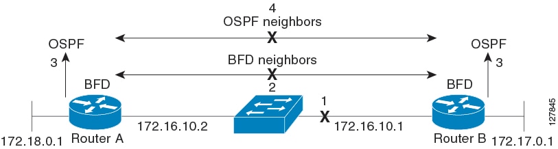
BFD provides fast BFD peer failure detection times independently of all media types, encapsulations, topologies, and routing protocols BGP, EIGRP, IS-IS, and OSPF. By sending rapid failure detection notices to the routing protocols in the local router to initiate the routing table recalculation process, BFD contributes to greatly reduced overall network convergence time. The figure below shows a simple network with two routers running OSPF and BFD. When OSPF discovers a neighbor (1) it sends a request to the local BFD process to initiate a BFD neighbor session with the OSPF neighbor router (2). The BFD neighbor session with the OSPF neighbor router is established (3).

The figure below shows what happens when a failure occurs in the network (1). The BFD neighbor session with the OSPF neighbor router is torn down (2). BFD notifies the local OSPF process that the BFD neighbor is no longer reachable (3). The local OSPF process tears down the OSPF neighbor relationship (4). If an alternative path is available, the routers will immediately start converging on it.
A routing protocol needs to register with BFD for every neighbor it acquires. Once a neighbor is registered, BFD initiates a session with the neighbor if a session does not already exist.
OSPF registers with BFD when:
A neighbor finite state machine (FSM) transitions to full state.
Both OSPF BFD and BFD are enabled.
On broadcast interfaces, OSPF establishes a BFD session only with the designated router (DR) and backup designated router (BDR), but not between any two routers in DROTHER state.
 Note |
A single BFD session notifies all protocols. For example, if OSFP and PIM neighbors exist, then a single BFD session notifies both the protocols. |
Once a BFD session has been established and timer negations are complete, BFD peers send BFD control packets that act in the same manner as an IGP hello protocol to detect liveliness, except at a more accelerated rate. The following information should be noted:
BFD is a forwarding path failure detection protocol. BFD detects a failure, but the routing protocol must take action to bypass a failed peer.
Cisco devices will use one BFD session for multiple client protocols in the Cisco implementation of BFD for Cisco IOS Releases 12.2(18)SXE, 12.0(31)S, and 12.4(4)T. For example, if a network is running OSPF and EIGRP across the same link to the same peer, only one BFD session will be established, and BFD will share session information with both routing protocols.
All BFD sessions come up as Version 1 by default and will be interoperable with Version 0. The system automatically performs BFD version detection, and BFD sessions between neighbors will run in the highest common BFD version between neighbors. For example, if one BFD neighbor is running BFD Version 0 and the other BFD neighbor is running Version 1, the session will run BFD Version 0. The output from the show bfd neighbors [details ] command will verify which BFD version a BFD neighbor is running.
Note |
RSP3 supports only Version 1 and do not support BFD version interoperability. |
See the Example Configuring BFD in an EIGRP Network with Echo Mode Enabled by Default for an example of BFD version detection.
The BFD process on the RP will handle the interaction with clients, which create and delete BFD sessions.
The BFD RP process will primarily own all BFD sessions on the router. It will pass the session creation and deletion requests to the BFD processes on all LCs. BFD LC sessions will have no knowledge of sessions being added or deleted by the clients. Only the BFD RP process will send session addition and deletion commands to the BFD LC process.
The BFD RP process will maintain a database of all the BFD sessions on the router. This database will contain only the minimum required information.
The BFD RP process services the BFD show commands.
Typically, when a networking device restarts, all routing peers of that device detect that the device went down and then came back up. This transition results in a routing flap, which could spread across multiple routing domains. Routing flaps caused by routing restarts create routing instabilities, which are detrimental to the overall network performance. Nonstop forwarding (NSF) helps to suppress routing flaps in devices that are enabled with stateful switchover (SSO), thereby reducing network instability.
NSF allows for the forwarding of data packets to continue along known routes while the routing protocol information is being restored after a switchover. With NSF, peer networking devices do not experience routing flaps. Data traffic is forwarded through intelligent line cards or dual forwarding processors while the standby RP assumes control from the failed active RP during a switchover. The ability of line cards and forwarding processors to remain up through a switchover and to be kept current with the Forwarding Information Base (FIB) on the active RP is key to NSF operation.
In devices that support dual RPs, SSO establishes one of the RPs as the active processor; the other RP is designated as the standby processor, and then synchronizes information between them. A switchover from the active to the standby processor occurs when the active RP fails, when it is removed from the networking device, or when it is manually taken down for maintenance.
The BFD protocol provides short-duration detection of failures in the path between adjacent forwarding engines. In network deployments that use dual RP routers or switches (to provide redundancy), the routers have a graceful restart mechanism that protects the forwarding state during a switchover between the active RP and the standby RP.
The dual RPs have variable switchover times that depend on the ability of the hardware to detect a communication failure. When BFD is running on the RP, some platforms are not able to detect a switchover before the BFD protocol times out; these platforms are referred to as slow switchover platforms.
To ensure a successful switchover to the standby RP, the BFD protocol uses checkpoint messages to send session information from the active RP Cisco IOS instance to the standby RP Cisco IOS instance. The session information includes local and remote discriminators, adjacent router timer information, BFD setup information, and session-specific information such as the type of session and the session version. In addition, the BFD protocol sends session creation and deletion checkpoint messages to create or delete a session on the standby RP.
The BFD sessions on the standby RP do not receive or send packets and do not process expired timers. These sessions wait for a switchover to occur and then send packets for any active sessions so that sessions do not time out on adjacent routers.
When the BFD protocol on the standby RP is notified of a switchover it changes its state to active, registers itself with Cisco Express Forwarding so that it can receive packets, and then sends packets for any elements that have expired.
BFD also uses checkpoint messages to ensure that sessions created by clients on the active RP are maintained during a switchover. When a switchover occurs, BFD starts an SSO reclaim timer. Clients must reclaim their sessions within the duration specified by the reclaim timer or else the session is deleted.
|
Maximum Number of BFD Sessions |
Chassis Type |
BFD Session Type |
Minimum Timer Value (ms) 1 |
Clients |
Comments |
|---|---|---|---|---|---|
|
1023 (IPv4) 64 (IPv6) |
RSP3 |
Async |
3.3 |
BGP, OSFP, ISIS, EIGRP |
NA |
|
64 (Software) |
RSP3 |
Async |
200 |
BGP, OSFP, ISIS, EIGRP |
NA |
|
511 (Hardware) (no client) 64 (Software) |
RSP3 |
BFD echo |
3.3 |
NA |
NA |
|
255 (Hardware) Scale 64 (Software) |
RSP3 |
BFD echo |
3.3 |
BGP, OSFP, ISIS, EIGRP |
NA |
Note |
On Cisco RSP3C-400-S, software BFD sessions may be impacted by CPU spikes. |
Note |
When BFD over IPv6 is configured, the maximum scale of BFD over IPv4 reduces to 64. |
Note |
Whenever BFD discriminators are exhausted an error message “BFD discrminators exhausted. No more sessions can be created” with traceback will be printed. |
Note |
Effective from the Cisco IOS XE Fuji 16.9.x onwards, Port-channel BFD (Micro-BFD as per RFC7130) on RSP3 is supported in both hardware offloaded and software offloaded. Hardware offloaded session timers are supported from 3.3 ms to 200 ms and software offloaded session timers are from 200 ms to 999 ms. |
Unlike dynamic routing protocols, such as OSPF and BGP, static routing has no method of peer discovery. Therefore, when BFD is configured, the reachability of the gateway is completely dependent on the state of the BFD session to the specified neighbor. Unless the BFD session is up, the gateway for the static route is considered unreachable, and therefore the affected routes will not be installed in the appropriate Routing Information Base (RIB).
For a BFD session to be successfully established, BFD must be configured on the interface on the peer and there must be a BFD client registered on the peer for the address of the BFD neighbor. When an interface is used by dynamic routing protocols, the latter requirement is usually met by configuring the routing protocol instances on each neighbor for BFD. When an interface is used exclusively for static routing, this requirement must be met by configuring static routes on the peers.
If a BFD configuration is removed from the remote peer while the BFD session is in the up state, the updated state of the BFD session is not signaled to IPv4 static. This will cause the static route to remain in the RIB. The only workaround is to remove the IPv4 static BFD neighbor configuration so that the static route no longer tracks BFD session state. Also, if you change the encapsulation type on a serial interface to one that is unsupported by BFD, BFD will be in a down state on that interface. The workaround is to shut down the interface, change to a supported encapsulation type, and then reconfigure BFD.
A single BFD session can be used by an IPv4 static client to track the reachability of next hops through a specific interface. You can assign a BFD group for a set of BFD-tracked static routes. Each group must have one active static BFD configuration, one or more passive BFD configurations, and the corresponding static routes to be BFD-tracked. Nongroup entries are BFD-tracked static routes for which a BFD group is not assigned. A BFD group must accommodate static BFD configurations that can be part of different VRFs. Effectively, the passive static BFD configurations need not be in the same VRF as that of the active configuration.
For each BFD group, there can be only one active static BFD session. You can configure the active BFD session by adding a static BFD configuration and a corresponding static route that uses the BFD configuration. The BFD session in a group is created only when there is an active static BFD configuration and the static route that uses the static BFD configuration. When the active static BFD configuration or the active static route is removed from a BFD group, all the passive static routes are withdrawn from the RIB. Effectively, all the passive static routes are inactive until an active static BFD configuration and a static route to be tracked by the active BFD session are configured in the group.
Similarly, for each BFD group, there can be one or more passive static BFD configurations and their corresponding static routes to be BFD-tracked. Passive static session routes take effect only when the active BFD session state is reachable. Though the active BFD session state of the group is reachable, the passive static route is added to the RIB only if the corresponding interface state is up. When a passive BFD session is removed from a group, it will not affect the active BFD session if one existed, or the BFD group reachability status.
Cisco IOS Release 15.1(3)S and later releases support BFD
on arbitrary paths, which might span multiple network hops. The BFD Multihop feature provides subsecond forwarding failure detection for a destination more than one hop, and up to 255 hops, away.
A BFD multihop session is set up between a unique source-destination address pair provided by the client. A session can be set up between two endpoints that have IP connectivity.
You must configure the bfd-template and bfd map commands to create a multihop template and associate it with one or more maps of destinations and associated BFD timers. You can enable authentication and configure a key chain for BFD multihop sessions.
Multi-hop BFD over IPv6 is supported in software mode only.
Starting Cisco IOS XE Gibraltar Release 16.11.1, BFD over Routed Pseudowire is supported on the router.
Routed VPLS is the ability to route or bridge frames to and from the pseudowire. Routed VPLS is configured by assigning the IP address under a bridge domain interface (BDI), in addition to the configuring the vfi command. Multi-Point (VPLS) is supported.
Both the virtual forwarding interface (VFI) and the IP address is configured under the BDI. This configuration makes the BDI multi-functional and unique to other previously possible interfaces.
Following configurations are supported on the BDI:
MPLS configuration
LDP configuration
Routed pseudowire supports Layer3 routing in addition to Layer2 bridging of frames to, and from the pseudowire.
Routed pseudowire does not support IPv6 BFD sessions.
Routed pseudowire does not support point to multipoint sessions.
Ensure that the minimum timer configuration is greater than the convergence time of the core network to avoid unnecessary flaps. For example, if the core network convergence time is 50 ms, BFD timer that is configured must be 50 ms *3.
 Caution |
A session flap may be seen while moving from explicit null to implicit null configuration or vice versa. |
When you deploy any feature, it is important to consider all the alternatives and be aware of any trade-offs being made.
The closest alternative to BFD in conventional EIGRP, IS-IS, and OSPF deployments is the use of modified failure detection mechanisms for EIGRP, IS-IS, and OSPF routing protocols.
If you set EIGRP hello and hold timers to their absolute minimums, the failure detection rate for EIGRP falls to within a one- to two-second range.
If you use fast hellos for either IS-IS or OSPF, these Interior Gateway Protocol (IGP) protocols reduce their failure detection mechanisms to a minimum of one second.
There are several advantages to implementing BFD over reduced timer mechanisms for routing protocols:
BFD on the CPU operates under interrupt like CEF switched traffic. EIGRP, IS-IS and OSPF protocol hellos are handled in the process switching path. This provides BFD greater scalability and reliability over protocol hellos.
Although reducing the EIGRP, IS-IS, and OSPF timers can result in minimum detection timer of one to two seconds, BFD can provide failure detection in less than one second.
Because BFD is not tied to any particular routing protocol, it can be used as a generic and consistent failure detection mechanism for EIGRP, IS-IS, and OSPF.
Because some parts of BFD can be distributed to the data plane, it can be less CPU-intensive than the reduced EIGRP, IS-IS, and OSPF timers, which exist wholly at the control plane.
Note |
RSP3 Module eysupports only the following BFD interval timers: 3.3ms, 6.6ms, 10ms, 20ms, 50ms, 100ms, 200ms ,999ms. It is recommended that peer should also configure the same timer values. |
|
Step 1 |
enable Example:Enables privileged EXEC mode.
|
|
Step 2 |
configure terminal Example:Enters global configuration mode. |
|
Step 3 |
bfd-template single-hop template-name Example:Creates a single-hop BFD template and enters BFD configuration mode. |
|
Step 4 |
interval min-tx milliseconds min-rx milliseconds multiplier multiplier-value Example:Configures the transmit and receive intervals between BFD packets, and specifies the number of consecutive BFD control packets that must be missed before BFD declares that a peer is unavailable. |
|
Step 5 |
interface gigabitethernet number Example:Specifies the Gigabit Ethernet interface and enters interface configuration mode. |
|
Step 6 |
Perform one of the following steps:
Example: |
|
Step 7 |
bfd template template name Enables the BFD template. |
|
Step 8 |
end Example:Exits interface configuration mode and returns to privileged EXEC mode. |
Perform this task to configure BFD support for static routing. Repeat the steps in this procedure on each BFD neighbor. For more information, see the "Example: Configuring BFD Support for Static Routing" section.
|
Step 1 |
enable Example:Enables privileged EXEC mode.
|
|
Step 2 |
configure terminal Example:Enters global configuration mode. |
|
Step 3 |
bfd-template single-hop template-name Example:Creates a single-hop BFD template and enters BFD configuration mode. |
|
Step 4 |
interval min-tx milliseconds min-rx milliseconds multiplier multiplier-value Example:Configures the transmit and receive intervals between BFD packets, and specifies the number of consecutive BFD control packets that must be missed before BFD declares that a peer is unavailable. |
|
Step 5 |
interface type number Example:Configures an interface and enters interface configuration mode. |
|
Step 6 |
Perform one of the following steps:
Example: |
|
Step 7 |
bfd template template name Enables the BFD template. |
|
Step 8 |
exit Example:Exits interface configuration mode and returns to global configuration mode. |
|
Step 9 |
Perform one of the following steps:
Example:Specifies a static route BFD neighbor.
|
|
Step 10 |
Perform one of the following steps:
Example:Specifies a static route BFD neighbor. |
|
Step 11 |
exit Example:Exits global configuration mode and returns to privileged EXEC mode. |
|
Step 12 |
Perform one of the following steps:
Example:(Optional) Displays static route database information. |
|
Step 13 |
Perform one of the following steps:
Example:(Optional) Displays information about the static BFD configuration from the configured BFD groups and nongroup entries. |
|
Step 14 |
exit Example:Exits privileged EXEC mode and returns to user EXEC mode. |
BFD echo mode is enabled by default, but you can disable it such that it can run independently in each direction.
BFD echo mode works with asynchronous BFD. Echo packets are sent by the forwarding engine and forwarded back along the same path in order to perform detection--the BFD session at the other end does not participate in the actual forwarding of the echo packets. The echo function and the forwarding engine are responsible for the detection process; therefore, the number of BFD control packets that are sent out between two BFD neighbors is reduced. In addition, because the forwarding engine is testing the forwarding path on the remote (neighbor) system without involving the remote system, there is an opportunity to improve the interpacket delay variance, thereby achieving quicker failure detection times than when using BFD Version 0 with BFD control packets for the BFD session.
Echo mode is described as without asymmetry when it is running on both sides (both BFD neighbors are running echo mode).
BFD can use the slow timer to slow down the asycnhronous session when the echo mode is enabled, and reduce the number of BFD control packets that are sent between two BFD neighbors. Also, the forwarding engine tests the forwarding path on the remote (neighbor) system without involving the remote system, so there is less interpacket delay variability and faster failure detection times.
BFD must be running on all participating routers.
Before using BFD echo mode, you must disable the sending of Internet Control Message Protocol (ICMP) redirect messages by entering the no ip icmp redirects command, in order to avoid high CPU utilization.
The baseline parameters for BFD sessions on the interfaces over which you want to run BFD sessions to BFD neighbors must be configured. See the Configuring BFD Session Parameters on the Interface section for more information.
BFD echo mode is supported only on single hop. Multi-hop is not supported.
BFD Echo mode is not supported on the RSP3 module in releases before Cisco IOS Fuji Release 16.9.1. The below restrictions apply if you bring up an echo BFD session. The following error message is displayed:
BFD template model:
Please remove bfd template <template name> from the
interface
add no echo to template
reapply bfd template <template name> on interface
BFD legacy configuration:
removal bfd interval <value> min_rx <value> multiplier
<value> or no bfd interval will also suffice
Now remove the bfd client configurations also i.e
Ex the client is ospf remove bfd all-interfaces under
ospf
Apply the  bfd interval <value> min_rx <value>
multiplier <value>
add no bfd echo
add back the bfd client configuration
If you configure BFD in non-echo mode and then move to echo RSP3, following error message is displayed:
"Echo Mode for ld = 0x%x not supported on RSP3\n"
        "add no echo to template name if configured via template\n"
        "or add no bfd echo to interface if configured\n"
        "via legacy(i.e bfd interval on the interface)
All BFD sessions use a single timer value for the echo interval.
BFD echo is supported onl on IPv4.
Minimum Timer value supported in 3.3ms.
BFD interval timer (Tx) values supported are (in ms) are 3.3, 6.6, 9.9, 20, 100, 200.
Maximum mumber of BFD echo sessions supported is 511, however the recommended scale per client is 255 (for example, 255 OSPF and 255 ISIS).
The BFD Clients supported are static route, OSPF/OSPFv3, BGP, EIGRP, ISIS, and HSRP.
When the session is in the UP state, use the shutdown and the no shutdown command on both sides to move BFD session from non echo mode to echo mode or vice versa.
If the BFD interval is configured with unsupported timer values, the BFD tx timer adjusts to its lower supported timer value.
The steps in this procedure show how to change the value of the BFD slow timer. Repeat the steps in this procedure for each BFD router.
|
Step 1 |
enable Example:Enables privileged EXEC mode.
|
|
Step 2 |
configure terminal Example:Enters global configuration mode. |
|
Step 3 |
bfd slow-timer milliseconds Example:Configures the BFD slow timer. |
|
Step 4 |
end Example:Exits global configuration mode and returns the router to privileged EXEC mode. |
The steps in this procedure show how to disable BFD echo mode without asymmetry—no echo packets will be sent by the router, and the router will not forward BFD echo packets that are received from any neighbor routers.
Repeat the steps in this procedure for each BFD router.
|
Step 1 |
enable Example:Enables privileged EXEC mode.
|
|
Step 2 |
configure terminal Example:Enters global configuration mode. |
|
Step 3 |
no bfd echo Example:Disables BFD echo mode.
|
|
Step 4 |
end Example:Exits global configuration mode and returns to privileged EXEC mode. |
Topology and Configuration
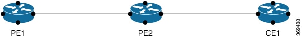
The Core consists of the PE1 and PE2 nodes where PE1 is the Routed pseudowire, and the CE node is the customer Layer3 interface. The BFD session is configured between the PE1 and CE node. VPLS is configured between PE1 and PE2.
Note |
The BFD session can also be configured between the two PE nodes. |
Configuration on the PE1 node
VPLS Configuration:
         ethernet evc EVC10
interface TenGigabitEthernet0/3/0
 service instance 10 ethernet EVC10
 encapsulation dot1q 10
 rewrite ingress tag pop 1 symmetric
 bridge-domain 10
         l2 vfi VPLS10 manual EVC10
          vpn id 10

          neighbor 192.168.10.1 encapsulation mpls

ROUTED PSEUDOWIRE configuration:
        interface BDI10
         ip address 192.0.2.1 255.255.255.0
         ip ospf 4 area 0
         bfd template BFD_HW-50ms

BFD TEMPLATE Confguration:
        router ospf 4
         bfd all-interfaces
        bfd-template single-hop BFD_HW-50ms
         interval min-tx 50 min-rx 50 multiplier 3
Configuration on the PE2 node
VPLS Configuration:
         l2 vfi VPLS10 manual EVC10
          vpn id 10
          bridge-domain 10
          neighbor 192.168.10.11 encapsulation mpls

ACCESS INTERFACE Configuration:
         interface te0/0/0
                           service instance 10 ethernet
          encapsulation dot1q 10
          rewrite ingress tag pop 1 symmetric
          bridge-domain 10
Configuration on the CE node
INTERFACE Configuration connected to PE2:
         interface te0/02/0
         service instance 10 ethernet
          encapsulation dot1q 10
          rewrite ingress tag pop 1 symmetric
          bridge-domain 10
BDI Configuration:
         interface BDI10
         ip address 192.0.2.2 255.255.255.0
         ip ospf 12 area 0
         bfd template BFD_HW-50ms
BFD Template Configuration:
        bfd-template single-hop BFD_HW-50ms
        interval  min-tx 50 min-rx 50 multiplier 3
        router ospf 12
        bfd all-interfaces
Use the show bfd neighbors command to verify the BFD over routed pseudowire configuration.
Router# show bfd neighbors details

IPv4 Sessions
NeighAddr LD/RD RH/RS State Int
192.0.2.1 1/1 Up Up BD10
Session state is UP and not using echo function.
Session Host: Hardware
OurAddr: 192.0.2.2
Handle: 1
Local Diag: 0, Demand mode: 0, Poll bit: 0
MinTxInt: 50000, MinRxInt: 50000, Multiplier: 3
Received MinRxInt: 50000, Received Multiplier: 3
Holddown (hits): 0(0), Hello (hits): 50(0)
Rx Count: 12441
Tx Count: 12507
Elapsed time watermarks: 0 0 (last: 0)
Registered protocols: OSPF CEF
Template: BFD_HW-50ms
Uptime: 00:10:28
Last packet: Version: 1 - Diagnostic: 0
 State bit: Up - Demand bit: 0
 Poll bit: 0 - Final bit: 0
 C bit: 1
 Multiplier: 3 - Length: 24
 My Discr.: 1 - Your Discr.: 1
 Min tx interval: 50000 - Min rx interval: 50000
Min Echo interval: 0You can configure a single-hop template to specify a set of BFD interval values. BFD interval values specified as part of the BFD template are not specific to a single interface. You can configure a multihop template to associate these values with one or more maps of destinations and associated BFD timers. You can enable authentication and configure a key chain for BFD multihop sessions.
Perform this task to create a BFD single-hop template and configure BFD interval timers.
|
Step 1 |
enable Example:Enables privileged EXEC mode.
|
|
Step 2 |
configure terminal Example:Enters global configuration mode. |
|
Step 3 |
bfd-template single-hop template-name Example:Creates a single-hop BFD template and enters BFD configuration mode. |
|
Step 4 |
interval min-tx milliseconds min-rx milliseconds multiplier multiplier-value Example:Configures the transmit and receive intervals between BFD packets, and specifies the number of consecutive BFD control packets that must be missed before BFD declares that a peer is unavailable. |
|
Step 5 |
end Example:Exits BFD configuration mode and returns the router to privileged EXEC mode. |
Perform this task to create a BFD multihop template and configure BFD interval timers, authentication, and key chain.
|
Step 1 |
enable Example:Enables privileged EXEC mode.
|
|
Step 2 |
configure terminal Example:Enters global configuration mode. |
|
Step 3 |
bfd-template multi-hop template-name Example:Creates a BFD multihop BFD template and enters BFD configuration mode. |
|
Step 4 |
interval min-tx milliseconds min-rx milliseconds multiplier multiplier-value Example:Configures the transmit and receive intervals between BFD packets, and specifies the number of consecutive BFD control packets that must be missed before BFD declares that a peer is unavailable. |
|
Step 5 |
authentication authentication-type keychain keychain-name Example:Configures authentication for the multihop template and specifies the authentication type. |
|
Step 6 |
end Example:Exits BFD configuration mode and returns the router to privileged EXEC mode. |
Perform this task to configure a BFD map that associates the interval timers and authentication configured in a template with unique source-destination address pairs for multihop BFD sessions.
You must configure a BFD multihop template before you associate it with a map.
|
Step 1 |
enable Example:Enables privileged EXEC mode.
|
|
Step 2 |
configure terminal Example:Enters global configuration mode. |
|
Step 3 |
Perform one of the following steps:
Example:Configures a BFD map and associates it with the template. Mention the VRF name for the source-address as well, if source address is part of a VRF. |
|
Step 4 |
end Example:Exits BFD configuration mode and returns the router to privileged EXEC mode. |
In the following example, the EIGRP network contains RouterA, RouterB, and RouterC. The Gigabit Ethernet interface 0/0/1 on RouterA is connected to the same network as Gigabit Ethernet interface 0/0/1 on Router B. The Gigabit Ethernet interface 0/0/1 on RouterB is connected to the same network as Gigabit Ethernet interface 0/0/1 on RouterC.
RouterA and RouterB are running BFD Version 1, which supports echo mode, and RouterC is running BFD Version 0, which does not support echo mode. The BFD sessions between RouterC and its BFD neighbors are said to be running echo mode with asymmetry because echo mode will run on the forwarding path for RouteA and RouterB, and their echo packets will return along the same path for BFD sessions and failure detections, while their BFD neighbor RouterC runs BFD Version 0 and uses BFD controls packets for BFD sessions and failure detections.
The example, starting in global configuration mode, shows the configuration of BFD.
interface Gigabtethernet0/0/0
 no shutdown
 ip address 10.4.9.14 255.255.255.0
 duplex auto
 speed auto
!
interface Gigabtethernet0/0/1
 ip address 172.16.1.1 255.255.255.0
 bfd interval 50 min_rx 50 multiplier 3
 no shutdown
 duplex auto
 speed auto
!
router eigrp 11
 network 172.16.0.0
 bfd all-interfaces
 auto-summary
!
!
interface Gigabtethernet0/0/0
 no shutdown
 ip address 10.4.9.34 255.255.255.0
 duplex auto
 speed auto
!
interface Gigabtethernet0/0/1
 ip address 172.16.1.2 255.255.255.0
 bfd interval 50 min_rx 50 multiplier 3
 no shtdown
 duplex auto
 speed auto
!
router eigrp 11
 network 172.16.0.0
 bfd all-interfaces
 auto-summary
!
!
!
interface Gigabtethernet0/0/0
 no shutdown
 ip address 10.4.9.51 255.255.255.0
 duplex auto
 speed auto
!
interface Gigabtethernet0/0/1
 ip address 172.16.1.3 255.255.255.0
 bfd interval 50 min_rx 50 multiplier 3
 no shutdown
 duplex auto
 speed auto
!
router eigrp 11
 network 172.16.0.0
 bfd all-interfaces
 auto-summary
!
The output from the show bfd neighbors details command from RouterA verifies that BFD sessions have been created among all three routers and that EIGRP is registered for BFD support. The first group of output shows that RouterC with the IP address 172.16.1.3 runs BFD Version 0 and therefore does not use the echo mode. The second group of output shows that RouterB with the IP address 172.16.1.2 does run BFD Version 1, and the 50 millisecond BFD interval parameter had been adopted. The relevant command output is shown in bold in the output.
RouterA# show bfd neighbors details

OurAddr
       NeighAddr
      LD/RD  RH/RS    Holdown(mult)  State     Int
172.16.1.1    172.16.1.3
     5/3    1(RH)    150 (3 )       Up         Gig0/0/1
Session state is UP and not using echo function.
Local Diag: 0, Demand mode: 0, Poll bit: 0
MinTxInt: 50000, MinRxInt: 50000, Multiplier: 3
Received MinRxInt: 50000, Received Multiplier: 3
Holdown (hits): 150(0), Hello (hits): 50(1364284)
Rx Count: 1351813, Rx Interval (ms) min/max/avg: 28/64/49 last: 4 ms ago
Tx Count: 1364289, Tx Interval (ms) min/max/avg: 40/68/49 last: 32 ms ago
Registered protocols: EIGRP
Uptime: 18:42:45
Last packet: Version: 0
            - Diagnostic: 0
             I Hear You bit: 1     - Demand bit: 0
             Poll bit: 0           - Final bit: 0
             Multiplier: 3         - Length: 24
             My Discr.: 3          - Your Discr.: 5
             Min tx interval: 50000    - Min rx interval: 50000
             Min Echo interval: 0
OurAddr       NeighAddr
     LD/RD  RH/RS   Holdown(mult)  State     Int
172.16.1.1    172.16.1.2

    6/1    Up        0    (3 )   Up        Gig0/0/1
Session state is UP and using echo function with 50 ms interval.
Local Diag: 0, Demand mode: 0, Poll bit: 0
MinTxInt: 1000000, MinRxInt: 1000000, Multiplier: 3
Received MinRxInt: 1000000, Received Multiplier: 3
Holdown (hits): 3000(0), Hello (hits): 1000(317)
Rx Count: 305, Rx Interval (ms) min/max/avg: 1/1016/887 last: 448 ms ago
Tx Count: 319, Tx Interval (ms) min/max/avg: 1/1008/880 last: 532 ms ago
Registered protocols: EIGRP
Uptime: 00:04:30
Last packet: Version: 1

         - Diagnostic: 0
             State bit: Up         - Demand bit: 0
             Poll bit: 0           - Final bit: 0
             Multiplier: 3         - Length: 24
             My Discr.: 1          - Your Discr.: 6
             Min tx interval: 1000000    - Min rx interval: 1000000
             Min Echo interval: 50000
The output from the show bfd neighbors details command on Router B verifies that BFD sessions have been created and that EIGRP is registered for BFD support. As previously noted, RouterA runs BFD Version 1, therefore echo mode is running, and RouterC runs BFD Version 0, so echo mode does not run. The relevant command output is shown in bold in the output.
RouterB# show bfd neighbors details

OurAddr       NeighAddr
     LD/RD  RH/RS   Holdown(mult)  State     Int
172.16.1.2    172.16.1.1
    1/6    Up        0    (3 )   Up        Gig0/0/1
Session state is UP and using echo function with 50 ms interval.
Local Diag: 0, Demand mode: 0, Poll bit: 0
MinTxInt: 1000000, MinRxInt: 1000000, Multiplier: 3
Received MinRxInt: 1000000, Received Multiplier: 3
Holdown (hits): 3000(0), Hello (hits): 1000(337)
Rx Count: 341, Rx Interval (ms) min/max/avg: 1/1008/882 last: 364 ms ago
Tx Count: 339, Tx Interval (ms) min/max/avg: 1/1016/886 last: 632 ms ago
Registered protocols: EIGRP
Uptime: 00:05:00
Last packet: Version: 1
           - Diagnostic: 0
             State bit: Up         - Demand bit: 0
             Poll bit: 0           - Final bit: 0
             Multiplier: 3         - Length: 24
             My Discr.: 6          - Your Discr.: 1
             Min tx interval: 1000000    - Min rx interval: 1000000
             Min Echo interval: 50000
OurAddr       NeighAddr

 LD/RD  RH/RS   Holdown(mult)  State     Int
172.16.1.2    172.16.1.3
     3/6    1(RH)     118  (3 )   Up        Gig0/0/1
Session state is UP and not using echo function.
Local Diag: 0, Demand mode: 0, Poll bit: 0
MinTxInt: 50000, MinRxInt: 50000, Multiplier: 3
Received MinRxInt: 50000, Received Multiplier: 3
Holdown (hits): 150(0), Hello (hits): 50(5735)
Rx Count: 5731, Rx Interval (ms) min/max/avg: 32/72/49 last: 32 ms ago
Tx Count: 5740, Tx Interval (ms) min/max/avg: 40/64/50 last: 44 ms ago
Registered protocols: EIGRP
Uptime: 00:04:45
Last packet: Version: 0
            - Diagnostic: 0
             I Hear You bit: 1     - Demand bit: 0
             Poll bit: 0           - Final bit: 0
             Multiplier: 3         - Length: 24
             My Discr.: 6          - Your Discr.: 3
             Min tx interval: 50000    - Min rx interval: 50000
             Min Echo interval: 0
When Gigabit ethernet interface 0/0/1 on RouterB fails, BFD will no longer detect Router B as a BFD neighbor for RouterA or for RouterC. In this example, Giagbit Ethernet interface 0/0/1has been administratively shut down on RouterB.
The following output from the show bfd neighbors command on RouterA now shows only one BFD neighbor for RouterA in the EIGRP network. The relevant command output is shown in bold in the output.
RouterA# show bfd neighbors
OurAddr       NeighAddr

    LD/RD  RH/RS   Holdown(mult)  State     Int
172.16.1.1    172.16.1.3

    5/3    1(RH)     134  (3 )   Up        Gig0/0/1
The following output from the show bfd neighbors command on RouterC also now shows only one BFD neighbor for RouterC in the EIGRP network. The relevant command output is shown in bold in the output.
RouterC# show bfd neighbors

OurAddr       NeighAddr

   LD/RD RH  Holdown(mult)  State     Int
172.16.1.3    172.16.1.1

3/5 1 114 (3 ) Up Gig0/0/1 In the following example, the simple OSPF network consists of Router A and Router B. Gigabit Ethernet interface 0/0/1 on Router A is connected to the same network as Gigabit Ethernet interface 0/0/1 in Router B. The example, starting in global configuration mode, shows the configuration of BFD. For both Routers A and B, BFD is configured globally for all interfaces associated with the OSPF process.
!
interface  Gigabitethernet 0/0/1
 ip address 172.16.10.1 255.255.255.0
 bfd interval 50 min_rx 50 multiplier 3
!
interface Gigabitethernet 0/0/0
ip address 172.17.0.1 255.255.255.0
!
router ospf 123
 log-adjacency-changes detail
 network 172.16.10.0 0.0.0.255 area 0
 network 172.17.10.0 0.0.0.255 area 0
 bfd all-interfaces
!
interface Gigabitethernet 0/0/1
 ip address 172.16.10.2 255.255.255.0
 bfd interval 50 min_rx 50 multiplier 3
!
interface Gigabitethernet 0/0/0
 ip address 172.18.0.1 255.255.255.0
!
router ospf 123
 log-adjacency-changes detail
 network 172.16.10.0 0.0.0.255 area 0
 network 172.18.10.0 0.0.0.255 area 0
 bfd all-interfaces
The output from the show bfd neighbors details command verifies that a BFD session has been created and that OSPF is registered for BFD support. The relevant command output is shown in bold in the output.
RouterA# show bfd neighbors details
OurAddr       NeighAddr     LD/RD RH  Holdown(mult)  State     Int
172.16.10.1   172.16.10.2    1/2  1   532  (3 )      Up        Gig0/0/0
Local Diag: 0, Demand mode: 0, Poll bit: 0
MinTxInt: 200000, MinRxInt: 200000, Multiplier: 5
Received MinRxInt: 1000, Received Multiplier: 3
Holdown (hits): 600(22), Hello (hits): 200(84453)
Rx Count: 49824, Rx Interval (ms) min/max/avg: 208/440/332 last: 68 ms ago
Tx Count: 84488, Tx Interval (ms) min/max/avg: 152/248/196 last: 192 ms ago
Registered protocols: OSPF
Uptime: 02:18:49
Last packet: Version: 0
            - Diagnostic: 0
             I Hear You bit: 1     - Demand bit: 0
             Poll bit: 0           - Final bit: 0
             Multiplier: 3         - Length: 24
             My Discr.: 2          - Your Discr.: 1
             Min tx interval: 50000    - Min rx interval: 1000
             Min Echo interval: 0
The output from the show bfd neighbors details command from Router B verifies that a BFD session has been created:
Router> show bfd neighbors details
Cleanup timer hits: 0
OurAddr       NeighAddr     LD/RD RH  Holdown(mult)  State     Int
172.16.10.2   172.16.10.1    8/1  1   1000 (5 )      Up        Gig0/0/0
Local Diag: 0, Demand mode: 0, Poll bit: 0
MinTxInt: 50000, MinRxInt: 1000, Multiplier: 3
Received MinRxInt: 200000, Received Multiplier: 5
Holdown (hits): 1000(0), Hello (hits): 200(5995)
Rx Count: 10126, Rx Interval (ms) min/max/avg: 152/248/196 last: 0 ms ago
Tx Count: 5998, Tx Interval (ms) min/max/avg: 204/440/332 last: 12 ms ago
Last packet: Version: 0            - Diagnostic: 0
             I Hear You bit: 1     - Demand bit: 0
             Poll bit: 0           - Final bit: 0
             Multiplier: 5         - Length: 24
             My Discr.: 1          - Your Discr.: 8
             Min tx interval: 200000    - Min rx interval: 200000
             Min Echo interval: 0
Uptime: 00:33:13
SSO Cleanup Timer called: 0
SSO Cleanup Action Taken: 0
Pseudo pre-emptive process count: 239103 min/max/avg: 8/16/8 last: 0 ms ago
 IPC Tx Failure Count: 0
 IPC Rx Failure Count: 0
 Total Adjs Found: 1
The output of the show ip ospf command verifies that BFD has been enabled for OSPF. The relevant command output is shown in bold in the output.
RouterA# show ip ospf

 Routing Process "ospf 123" with ID 172.16.10.1
 Supports only single TOS(TOS0) routes
 Supports opaque LSA
 Supports Link-local Signaling (LLS)
 Initial SPF schedule delay 5000 msecs
 Minimum hold time between two consecutive SPFs 10000 msecs
 Maximum wait time between two consecutive SPFs 10000 msecs
 Incremental-SPF disabled
 Minimum LSA interval 5 secs
 Minimum LSA arrival 1000 msecs
 LSA group pacing timer 240 secs
 Interface flood pacing timer 33 msecs
 Retransmission pacing timer 66 msecs
 Number of external LSA 0. Checksum Sum 0x000000
 Number of opaque AS LSA 0. Checksum Sum 0x000000
 Number of DCbitless external and opaque AS LSA 0
 Number of DoNotAge external and opaque AS LSA 0
 Number of areas in this router is 1. 1 normal 0 stub 0 nssa
 External flood list length 0
 BFD is enabled
    Area BACKBONE(0)
        Number of interfaces in this area is 2 (1 loopback)
        Area has no authentication
        SPF algorithm last executed 00:00:08.828 ago
        SPF algorithm executed 9 times
        Area ranges are
        Number of LSA 3. Checksum Sum 0x028417
        Number of opaque link LSA 0. Checksum Sum 0x000000
        Number of DCbitless LSA 0
        Number of indication LSA 0
        Number of DoNotAge LSA 0
        Flood list length 0
RouterB# show ip ospf

 Routing Process "ospf 123" with ID 172.18.0.1
 Supports only single TOS(TOS0) routes
 Supports opaque LSA
 Supports Link-local Signaling (LLS)
 Supports area transit capability
 Initial SPF schedule delay 5000 msecs
 Minimum hold time between two consecutive SPFs 10000 msecs
 Maximum wait time between two consecutive SPFs 10000 msecs
 Incremental-SPF disabled
 Minimum LSA interval 5 secs
 Minimum LSA arrival 1000 msecs
 LSA group pacing timer 240 secs
 Interface flood pacing timer 33 msecs
 Retransmission pacing timer 66 msecs
 Number of external LSA 0. Checksum Sum 0x0
 Number of opaque AS LSA 0. Checksum Sum 0x0
 Number of DCbitless external and opaque AS LSA 0
 Number of DoNotAge external and opaque AS LSA 0
 Number of areas in this router is 1. 1 normal 0 stub 0 nssa
 Number of areas transit capable is 0
 External flood list length 0
 BFD is enabled
    Area BACKBONE(0)
        Number of interfaces in this area is 2 (1 loopback)
        Area has no authentication
        SPF algorithm last executed 02:07:30.932 ago
        SPF algorithm executed 7 times
        Area ranges are
        Number of LSA 3. Checksum Sum 0x28417
        Number of opaque link LSA 0. Checksum Sum 0x0
        Number of DCbitless LSA 0
        Number of indication LSA 0
        Number of DoNotAge LSA 0
        Flood list length 0
The output of the show ip ospf interface command verifies that BFD has been enabled for OSPF on the interfaces connecting Router A and Router B. The relevant command output is shown in bold in the output.
RouterA# show ip ospf interface GigabitEthernet 0/0/1

GigabitEthernet0/0/1 is up, line protocol is up
  Internet Address 172.16.10.1/24, Area 0
  Process ID 123, Router ID 172.16.10.1, Network Type BROADCAST, Cost: 1
  Transmit Delay is 1 sec, State BDR, Priority 1, BFD enabled
  Designated Router (ID) 172.18.0.1, Interface address 172.16.10.2
  Backup Designated router (ID) 172.16.10.1, Interface address 172.16.10.1
  Timer intervals configured, Hello 10, Dead 40, Wait 40, Retransmit 5
    oob-resync timeout 40
    Hello due in 00:00:03
  Supports Link-local Signaling (LLS)
  Index 1/1, flood queue length 0
  Next 0x0(0)/0x0(0)
  Last flood scan length is 1, maximum is 1
  Last flood scan time is 0 msec, maximum is 0 msec
  Neighbor Count is 1, Adjacent neighbor count is 1
    Adjacent with neighbor 172.18.0.1  (Designated Router)
  Suppress hello for 0 neighbor(s)
RouterB# show ip ospf interface Gigabit Ethernet 0/0/0
GigabitEthernet0/0/1 is up, line protocol is up
  Internet Address 172.18.0.1/24, Area 0
  Process ID 123, Router ID 172.18.0.1, Network Type BROADCAST, Cost: 1
  Transmit Delay is 1 sec, State DR, Priority 1, BFD enabled
  Designated Router (ID) 172.18.0.1, Interface address 172.18.0.1
  No backup designated router on this network
  Timer intervals configured, Hello 10, Dead 40, Wait 40, Retransmit 5
    oob-resync timeout 40
    Hello due in 00:00:01
  Supports Link-local Signaling (LLS)
  Index 1/1, flood queue length 0
  Next 0x0(0)/0x0(0)
  Last flood scan length is 0, maximum is 0
  Last flood scan time is 0 msec, maximum is 0 msec
  Neighbor Count is 0, Adjacent neighbor count is 0
Suppress hello for 0 neighbor(s)In the following example, the simple BGP network consists of Router A and Router B. The Gigabit Ethernet interface 0/0/1 on Router A is connected to the same network as Gigabit Ethernet interface 0/0/1 in Router B. The example, starting in global configuration mode, shows the configuration of BFD.
!
interface GigabitEthernet 0/0/1
 ip address 172.16.10.1 255.255.255.0
 bfd interval 50 min_rx 50 multiplier 3
!
interface GigabitEthernet 0/0/0
ip address 172.17.0.1 255.255.255.0
!
!
router bgp 40000
 bgp log-neighbor-changes
 neighbor 172.16.10.2 remote-as 45000
 neighbor 172.16.10.2 fall-over bfd
 !
 address-family ipv4
 neighbor 172.16.10.2 activate
 no auto-summary
 no synchronization
 network 172.18.0.0 mask 255.255.255.0
 exit-address-family
!
!
interface GigabitEthernet 0/0/1
 ip address 172.16.10.2 255.255.255.0
 bfd interval 50 min_rx 50 multiplier 3
!
interface GigabitEthernet 0/0/0
 ip address 172.18.0.1 255.255.255.0
!
router bgp 45000
 bgp log-neighbor-changes
 neighbor 172.16.10.1 remote-as 40000
 neighbor 172.16.10.1 fall-over bfd
 !
 address-family ipv4
 neighbor 172.16.10.1 activate
 no auto-summary
 no synchronization
 network 172.17.0.0 mask 255.255.255.0
 exit-address-family
!
The output from the show bfd neighbors details command from Router A verifies that a BFD session has been created and that BGP is registered for BFD support. The relevant command output is shown in bold in the output.
RouterA# show bfd neighbors details

OurAddr       NeighAddr     LD/RD RH  Holdown(mult)  State     Int
172.16.10.1   172.16.10.2    1/8  1   332  (3 )      Up        Gig0/0/1
Local Diag: 0, Demand mode: 0, Poll bit: 0
MinTxInt: 200000, MinRxInt: 200000, Multiplier: 5
Received MinRxInt: 1000, Received Multiplier: 3
Holdown (hits): 600(0), Hello (hits): 200(15491)
Rx Count: 9160, Rx Interval (ms) min/max/avg: 200/440/332 last: 268 ms ago
Tx Count: 15494, Tx Interval (ms) min/max/avg: 152/248/197 last: 32 ms ago
Registered protocols: BGP
Uptime: 00:50:45
Last packet: Version: 0            - Diagnostic: 0
             I Hear You bit: 1     - Demand bit: 0
             Poll bit: 0           - Final bit: 0
             Multiplier: 3         - Length: 24
             My Discr.: 8          - Your Discr.: 1
             Min tx interval: 50000    - Min rx interval: 1000
             Min Echo interval: 0
The output from the show bfd neighbors details command on Router B verifies that a BFD session has been created:
Router> show bfd neighbors details
Cleanup timer hits: 0
OurAddr       NeighAddr     LD/RD RH  Holdown(mult)  State     Int
172.16.10.2   172.16.10.1    8/1  1   1000 (5 )      Up        Gig0/0/0
Local Diag: 0, Demand mode: 0, Poll bit: 0
MinTxInt: 50000, MinRxInt: 1000, Multiplier: 3
Received MinRxInt: 200000, Received Multiplier: 5
Holdown (hits): 1000(0), Hello (hits): 200(5995)
Rx Count: 10126, Rx Interval (ms) min/max/avg: 152/248/196 last: 0 ms ago
Tx Count: 5998, Tx Interval (ms) min/max/avg: 204/440/332 last: 12 ms ago
Last packet: Version: 0            - Diagnostic: 0
             I Hear You bit: 1     - Demand bit: 0
             Poll bit: 0           - Final bit: 0
             Multiplier: 5         - Length: 24
             My Discr.: 1          - Your Discr.: 8
             Min tx interval: 200000    - Min rx interval: 200000
             Min Echo interval: 0
Uptime: 00:33:13
SSO Cleanup Timer called: 0
SSO Cleanup Action Taken: 0
Pseudo pre-emptive process count: 239103 min/max/avg: 8/16/8 last: 0 ms ago
 IPC Tx Failure Count: 0
 IPC Rx Failure Count: 0
 Total Adjs Found: 1
The output of the show ip bgp neighbors command verifies that BFD has been enabled for the BGP neighbors:
RouterA# show ip bgp neighbors
BGP neighbor is 172.16.10.2,  remote AS 45000, external link
 Using BFD to detect fast fallover
.
.
.
RouterB# show ip bgp neighbors
BGP neighbor is 172.16.10.1,  remote AS 40000, external link
 Using BFD to detect fast fallover
.
.
.The Cisco IOS XE implementation of IS-IS conforms to the specifications detailed in RFC 6213. The IS-IS router advertises its BFD-enabled interfaces by including type-length-value (TLV) in the IS-IS Hello (IIH) PDU. The BFD-enabled TLV includes the topologies and protocols that it supports along with the appropriate Multi-Topology Identifier (MTID) or Network Layer Protocol Identifier (NLPID) pairs. Note that when the router sends an IIH to a non-BFD-enabled interface, it omits the TLV.
In the following example, the simple IS-IS network consists of Router A and Router B. The Gigabit Ethernet interface 0/0/0 on Router A is connected to the same network as Gigabit Ethernet interface 0/0/0 for Router B. The example, starting in global configuration mode, shows the configuration of BFD.
!
interface GigabitEthernet 0/0/0
 ip address 209.165.200.226 255.255.255.224
ip router isis
 bfd interval 50 min_rx 50 multiplier 3
!
router isis
 net 49.0001.1720.1600.1001.00
 bfd all-interfaces
!
!
interface GigabitEthernet 0/0/0
 ip address 209.165.200.227 255.255.255.224
ip router isis
 bfd interval 50 min_rx 50 multiplier 3
!
router isis
 net 49.0000.0000.0002.00
 bfd all-interfaces
!
The output from the show bfd neighbors detail command from Router A verifies that a BFD session has been created and that IS-IS is registered for BFD support:
RouterA# show bfd neighbors detail

OurAddr             NeighAddr         LD/RD RH  Holdown(mult)  State     Int
209.165.200.226   209.165.200.227    1/8  1   536  (3 )      Up        Gig0/0/0
Local Diag: 0, Demand mode: 0, Poll bit: 0
MinTxInt: 200000, MinRxInt: 200000, Multiplier: 5
Received MinRxInt: 1000, Received Multiplier: 3
Holdown (hits): 600(0), Hello (hits): 200(23543)
Rx Count: 13877, Rx Interval (ms) min/max/avg: 200/448/335 last: 64 ms ago
Tx Count: 23546, Tx Interval (ms) min/max/avg: 152/248/196 last: 32 ms ago
Registered protocols: ISIS
Uptime: 01:17:09
Last packet: Version: 0            - Diagnostic: 0
             I Hear You bit: 1     - Demand bit: 0
             Poll bit: 0           - Final bit: 0
             Multiplier: 3         - Length: 24
             My Discr.: 8          - Your Discr.: 1
             Min tx interval: 50000    - Min rx interval: 1000
             Min Echo interval: 0
The output from the show bfd neighbors detail command from the line card on Router B verifies that a BFD session has been created:
Router> show bfd neighbors detail
Cleanup timer hits: 0
OurAddr             NeighAddr       LD/RD RH  Holdown(mult)  State     Int
209.165.200.227   209.165.200.226    8/1  1   1000 (5 )      Up        Gig0/0/0
Local Diag: 0, Demand mode: 0, Poll bit: 0
MinTxInt: 50000, MinRxInt: 1000, Multiplier: 3
Received MinRxInt: 200000, Received Multiplier: 5
Holdown (hits): 1000(0), Hello (hits): 200(5995)
Rx Count: 10126, Rx Interval (ms) min/max/avg: 152/248/196 last: 0 ms ago
Tx Count: 5998, Tx Interval (ms) min/max/avg: 204/440/332 last: 12 ms ago
Last packet: Version: 0            - Diagnostic: 0
             I Hear You bit: 1     - Demand bit: 0
             Poll bit: 0           - Final bit: 0
             Multiplier: 5         - Length: 24
             My Discr.: 1          - Your Discr.: 8
             Min tx interval: 200000    - Min rx interval: 200000
             Min Echo interval: 0
Uptime: 00:33:13
SSO Cleanup Timer called: 0
SSO Cleanup Action Taken: 0
Pseudo pre-emptive process count: 239103 min/max/avg: 8/16/8 last: 0 ms ago
 IPC Tx Failure Count: 0
 IPC Rx Failure Count: 0
Total Adjs Found: 1The output from the show isis neighbors detail command from the line card on Router B shows the TLV field in the IS-IS Hello (IIH) PDU through which IS-IS responds to a BFD-detected forwarding plane failure. See Intermediate System-to-Intermediate System (IS-IS) TLVs for more information on TLV.
Router> show isis neighbors detail
PE1 L1 interface GigabitEthernet 0/0/0 209.165.200.226 UP 20 04
Area Address(es): 49
SNPA: e8ed.f3b8.d115
State Changed: 00:03:17
Format: Phase V
Remote TID: 0
Local TID: 0
Interface name: GigabitEthernet 0/0/0
Neighbor Circuit Id: 4
Remote BFD Support:TLV (MTID:0, IPV4) -----Remote BFD TLV’s received from neighbor
peer
BFD enabled: (MTID:0, ipv4) --------BFD TLV’s sent from Router B port
Adj sync: FullIn the following example, the HSRP network consists of Router A and Router B. The Gigabit Ethernet interface 2/0 on Router A is connected to the same network as Gigabit Ethernet interface 2/0 on Router B. The example, starting in global configuration mode, shows the configuration of BFD.
Note |
In the following example, the standby bfd and the standby bfd all-interfaces commands are not displayed. HSRP support for BFD peering is enabled by default when BFD is configured on the router or interface using the bfd interval command. The standby bfd and standby bfd all-interfaces commands are needed only if BFD has been manually disabled on a router or interface. |
Note |
The following configurations are in legacy mode. Legacy mode is not supported on Cisco RSP3. To configure on Cisco RSP3, use the template mode configuration as shown in Configuring BFD Session Parameters on the Interface section. |
interface GigabitEthernet0/0/1
 no shutdown
 ip address 10.0.0.1 255.0.0.0
 bfd interval 200 min_rx 200 multiplier 3
 standby 1 ip 10.0.0.11
 standby 1 preempt
 standby 1 priority 110

 standby 2 ip 10.0.0.12
 standby 2 preempt
 standby 2 priority 110
interface GigabitEthernet0/0/1
 ip address 10.1.0.22 255.255.0.0
 no shutdown
 bfd interval 200 min_rx 200 multiplier 3
 standby 1 ip 10.0.0.11
 standby 1 preempt
 standby 1 priority 90
 standby 2 ip 10.0.0.12
 standby 2 preempt
 standby 2 priority 80
The output from the show standby neighbors command verifies that a BFD session has been created:
RouterA#show standby neighbors

HSRP neighbors on GigabitEthernet0/0/0
  10.1.0.22
    No active groups
    Standby groups: 1
    BFD enabled !
RouterB# show standby neighbors

HSRP neighbors on GigabitEthernet0/0/1
  10.0.0.2
    Active groups: 1
    No standby groups
BFD enabled !In the following example, the network consists of Device A and Device B. Serial interface 2/0 on Device A is connected to the same network as serial interface 2/0 on Device B. In order for the BFD session to come up, Device B must be configured.
Note |
The following configurations are in legacy mode. Legacy mode is not supported on Cisco RSP3. To configure on Cisco RSP3, use the template mode configuration as shown in Configuring BFD Session Parameters on the Interface section. |
configure terminal
interface Serial 2/0
ip address 10.201.201.1 255.255.255.0
bfd interval 500 min_rx 500 multiplier 5
ip route static bfd Serial 2/0 10.201.201.2
ip route 10.0.0.0 255.0.0.0 Serial 2/0 10.201.201.2
configure terminal
interface Serial 2/0
ip address 10.201.201.2 255.255.255.0
bfd interval 500 min_rx 500 multiplier 5
ip route static bfd Serial 2/0 10.201.201.1
ip route 10.1.1.1 255.255.255.255 Serial 2/0 10.201.201.1
Note that the static route on Device B exists solely to enable the BFD session between 10.201.201.1 and 10.201.201.2. If there is no useful static route that needs to be configured, select a prefix that will not affect packet forwarding, for example, the address of a locally configured loopback interface.
In the following example, there is an active static BFD configuration to reach 209.165.200.225 through Gigabit Ethernet interface 0/0/0 in the BFD group testgroup. As soon as the static route is configured that is tracked by the configured static BFD, a single hop BFD session is initiated to 209.165.200.225 through Ethernet interface 0/0. The prefix 10.0.0.0/8 is added to the RIB if a BFD session is successfully established.
configure terminal
ip route static bfd GigabitEthernet 0/0/0 209.165.200.225 group testgroup
ip route 10.0.0.0 255.255.255.224 Ethernet 0/0 209.165.200.225
In the following example, a BFD session to 209.165.200.226 through Ethernet interface 0/0.1001 is marked to use the group testgroup. That is, this configuration is a passive static BFD. Though there are static routes to be tracked by the second static BFD configuration, a BFD session is not triggered for 209.165.200.226 through Gigabit Ethernet interface 0/0/0. The existence of the prefixes 10.1.1.1/8 and 10.2.2.2/8 is controlled by the active static BFD session (Gigabit Ethernet interface 0/0/0 209.165.200.225).
configure terminal
ip route static bfd GigabitEthernet 0/0/0 209.165.200.225 group testgroup
ip route 10.0.0.0 255.255.255.224 GigabitEthernet 0/0/0 209.165.200.225
ip route static bfd Ethernet 0/0.1001 209.165.200.226 group testgroup passive
ip route 10.1.1.1 255.255.255.224 GigabitEthernet 0/0/0 209.165.200.226
ip route 10.2.2.2 255.255.255.224 GigabitEthernet 0/0/0 209.165.200.226|
Feature Name |
Release |
Description |
|---|---|---|
|
BFD Dampening |
Cisco IOS XE Amsterdam 17.3.1 |
Bidirectional Forwarding Detection (BFD) is a detection protocol that is designed to provide fast forwarding path failure detection for encapsulations, topologies, and routing protocols. BFD provides a consistent failure detection method. BFD detects forwarding path failures at a uniform rate, rather than the variable rates for different routing protocol. This feature is supported on the RSP2 module. |
The BFD Dampening feature introduces a configurable exponential delay mechanism. This mechanism is designed to suppress the excessive effect of remote node reachability events flapping with BFD. The BFD Dampening feature allows the network operator to automatically dampen a given BFD session to prevent excessive notification to BFD clients, thus preventing unnecessary instability in the network. Dampening the notification to a BFD client suppresses BFD notification until the time the session under monitoring stops flapping and becomes stable.
Configuring the BFD Dampening feature, especially on a high-speed interface with routing clients, improves convergence time and stability throughout the network. (For routing client: minimize route recomputation, prefix flushing and learning due to stop or restart of routing protocol, translating in turn into reduced utilization of system processing resources by other devices in the network).
When reachability to the node under monitoring is flapping, penalty is assigned to that session. Penalty is gradually increased as long as the session state is not stable. Penalty is suppressed when next hop reachability becomes stable (during less flapping). There are different configuration parameters that are introduced in addressing this requirement namely Suppress Threshold, Half-Life period, Reuse Threshold and maximum suppress time.
BFD session dampening can be applied to all types of BFD sessions including IPv4 or IPv6 single-hop or multihop and so on. BFD session dampening is configured through bfd-template CLI at global level.
BFD Dampening is not supported on BFD multihop client and Micro BFD.
BFD Dampening with down monitoring, does not work for multihop sessions.
|
Step 1 |
enable Example:Enables privileged EXEC mode.
|
||
|
Step 2 |
configure terminal Example:Enters global configuration mode. |
||
|
Step 3 |
bfd-template multi-hop template-name Example:Creates a Bidirectional Forwarding Detection (BFD) template and enters BFD configuration mode. |
||
|
Step 4 |
interval min-tx milliseconds min-rx milliseconds multiplier multiplier-value Example:Configures the transmit and receive intervals between BFD packets, and specifies the number of consecutive BFD control packets that must be missed before BFD declares that a peer is unavailable. |
||
|
Step 5 |
dampening [half-life-period reuse-threshold suppress-threshold max-suppress-time stability-threshold down-monitoring] Example:Configures a device to dampen a flapping session.
|
||
|
Step 6 |
end Example:Exits BFD configuration mode and returns to privileged EXEC mode. |
Following command shows the dampening specific details if enabled for the session.
IPv4 Sessions
NeighAddr                              LD/RD         RH/RS     State     Int
10.0.0.2                               1/0            Up         Up     Et0/0
Session Host: Software
OurAddr: 10.0.0.1
Handle: 1
Local Diag: 0, Demand mode: 0, Poll bit: 0
MinTxInt: 1000000, MinRxInt: 1000000, Multiplier: 3
Received MinRxInt: 0, Received Multiplier: 0
Holddown (hits): 0(0), Hello (hits): 1000(0)
Rx Count: 0, Rx Interval (ms) min/max/avg: 0/0/0 last: 1257099 ms ago
Tx Count: 0, Tx Interval (ms) min/max/avg: 0/0/0 last: 1257099 ms ago
Elapsed time watermarks: 0 0 (last: 0)
Dampening:   penalty: 0                       - not dampened
             flap count: 0                    - halflife: 2 sec
             reuse threshold: 2000            - suppress threshold: 3000
             max suppress time: 6 sec
Registered protocols: BGP CEF
Last packet: Version: 1                  - Diagnostic: 0
             State bit: AdminDown        - Demand bit: 0
             Poll bit: 0                 - Final bit: 0
             C bit: 0
             Multiplier: 0               - Length: 0
             My Discr.: 0                - Your Discr.: 0
             Min tx interval: 0          - Min rx interval: 0
             Min Echo interval: 0
Following command displays the dampening information about the BFD sessions configured with BFD dampening.
IPv4 Multihop Sessions
NeighAddr[vrf]                                LD/RD         RH/RS     State
20.0.0.1                                      1/0           Up          Up
Dampening:   penalty: 0                       - not dampened
             flap count: 0                    - halflife: 2 sec
             reuse threshold: 2000            - suppress threshold: 3000
                       max suppress time: 6 sec
Following command displays the dampening information about the BFD sessions that are dampened.
IPv4 Sessions
NeighAddr[vrf]                                LD/RD         RH/RS     State
20.0.0.1                                      1/0           Down      Down
Dampening:   penalty: 4500                      - dampened
             flap count: 10                     - halflife: 2 sec
             reuse threshold: 2000              - suppress threshold: 3000
                       max suppress time: 6 sec
Use detail keyword to view the entire session information.
IPv4 Sessions
NeighAddr                              LD/RD         RH/RS     State     Int
1.1.1.2                                 1/1          Up        Up        Et0/0
Session state is UP and using echo function with 50 ms interval.
Session Host: Software
OurAddr: 10.0.0.1
Handle: 1
Local Diag: 0, Demand mode: 0, Poll bit: 0
MinTxInt: 1000000, MinRxInt: 1000000, Multiplier: 3
Received MinRxInt: 1000000, Received Multiplier: 3
Holddown (hits): 0(0), Hello (hits): 1000(181)
Rx Count: 259, Rx Interval (ms) min/max/avg: 1/1000/663 last: 58 ms ago
Tx Count: 297, Tx Interval (ms) min/max/avg: 1/1000/578 last: 58 ms ago
Elapsed time watermarks: 0 0 (last: 0)
Dampening: Penalty: 4999             - dampened
           Flap Count: 38            - Half Life: 2 sec
           Reuse Threshold: 1000     - Suppress Threshold: 3000
           Max suppress time: 5 sec
Registered protocols: BGP CEF
Template: damp
Uptime: 00:00:00
Last packet: Version: 1                  - Diagnostic: 0
             State bit: Up               - Demand bit: 0
             Poll bit: 0                 - Final bit: 0
             C bit: 0
             Multiplier: 3               - Length: 24
             My Discr.: 1                - Your Discr.: 1
             Min tx interval: 1000000    - Min rx interval: 1000000
Router# show bfd neigh dampened

IPv4 Sessions
NeighAddr                              LD/RD         RH/RS     State     Int
1.1.1.2                                 3/3          Down      Down      BD10
Dampening: Penalty: 353              - dampened(down monitoring)
           Flap Count: 3             - Half Life: 4 seconds
           Reuse Threshold: 200      - Suppress Threshold: 1000
           Max suppress time  : 10 seconds
           Time to unsupress  : 4 seconds
           Stability threshold: 60 seconds
           Exponential Backoff counter: 0
Router# show bfd neigh dampening

IPv4 Sessions
NeighAddr                              LD/RD         RH/RS     State     Int
1.1.1.2                                 3/3          Up        Up        BD10
Dampening: Penalty: 1                - not dampened(down monitoring)
           Flap Count: 3             - Half Life: 4 seconds
           Reuse Threshold: 200      - Suppress Threshold: 1000
           Max suppress time  : 10 seconds
           Time to unsupress  : 0 seconds
           Stability threshold: 60 seconds
           Exponential Backoff counter: 1
To enable fast detection of link failure in a port channel, BFD sessions are run on every member link of the port channel. The BFD session that is mapped to a member link is referred to as a micro-BFD session. The micro-BFD sessions on the member links are independent BFD sessions.
|
Feature Name |
Release |
Description |
|---|---|---|
|
Micro BFD Support on Port Channel with EFPs |
Cisco IOS XE Dublin 17.11.1 |
A Micro Bidirectional Forwarding Detection (Micro-BFD) session detects failures in member links of a port channel. You can now enable Micro-BFD sessions for a port channel on which Ethernet flow Point (EFP) or service instance is configured. This feature ensures that traffic is forwarded to a member link only when the micro-BFD session for that member link is in the UP state. As part of this feature, the source-service-instance number keyword has been added to the port-channel bfd command. The specified service instance provides the source IP address for the micro-BFD session. This feature is supported on the Cisco RSP3 module. |
|
Micro BFD over LAG Convergence Optimization |
Cisco IOS XE Bengaluru 17.6.1 |
Starting with 17.6.x release, the convergence for port-channel failures with Fast Reroute (FRR) is less than 50 milliseconds, when min-links is configured and equal to the total-links available under the port-channel. This feature is supported on the Cisco RSP3 module. |
For port channels with EFPs, Micro-BFD establishes the session with the source and destination as follows:
Micro BFD is supported both in hardware offloaded and software offloaded.
Timers supported on micro BFD hardware offloaded session are from 3.3 ms to 200 ms.
Micro BFD supports Active/Active SDM template for port-channel for Cisco RSP3 module.
Interior gateway protocol is not necessary for the micro BFD sessions to be up between the LAG.
The client for micro BFD sessions is port-channel.
Micro BFD is supported on port-channel with member links from different ASICs.
Micro BFD is supported with LACP minimum links and LACP maximum links enabled on the port-channel.
The convergence achieved with this feature is less than 50 ms with BFD timers configured to 3.3ms with multiplier value as 3.
Runs BFD session over each Link Aggregation Group (LAG) member link.
Verifies link continuity for every member link.
Makes BFD to control the LAG member link to be part of the Layer 2 load-balancing table of the LAG interface in the presence or the absence of Link Aggregation Control Protocol (LACP).
Offloads the continuity check messages.
Provides a sub 50 millisecond convergence for LAG failures for releases before 17.6.x. Starting with Cisco IOS XE Bengaluru 17.6.x release, the convergence for port-channel failures with Fast Reroute (FRR) is less than 50 milliseconds, when min-links is configured and equal to the total-links available under the port-channel.
Micro BFD supports single hop only.
Micro BFD works only with IPv4.
Micro BFD does not support ECHO mode.
Maximum tested scale is sessions .
Perform the following steps to configure micro BFD:
Configure port channel. See Configure Port-Channel.
If Micro BFD needs to be enabled on an Active/Active SDM template, enable port channel, then enable the SDM template for the port channel ID before configuring the port-channel. See Configuring QoS Support on Port Channel Active Active and Selecting the SDM template.
Configure BFD template. See Configure Micro BFD on Port Channel.
Configure Micro BFD over port-channel with the template configured. See Configure Micro BFD on Port Channel.
|
Step 1 |
enable Example:Enables privileged EXEC mode. Enter your password if prompted. |
|
Step 2 |
configure terminal Example:Enters the global configuration mode. |
|
Step 3 |
Interface port channel number Example:Configures the port channel and enters the interface mode. |
|
Step 4 |
ip address ip-address mask Example:Configures an IP address for the interface. |
|
Step 5 |
Interface interface typeinterface name Example:Specifies the ethernet interface. |
|
Step 6 |
channel group channel group number mode mode name Example:The following types of port channel modes can be configured:
|
|
Step 7 |
end Exits the interface range configuration mode and returns to the configuration mode. |
Use the commands below to verify the port channel summary details:
Device#show etherchannel summary
	Flags:  D - down        P/bndl - bundled in port-channel
        I - stand-alone s/susp - suspended
        H - Hot-standby (LACP only)
        R - Layer3      S - Layer2
        U - in use      f - failed to allocate aggregator

        M - not in use, minimum links not met
        u - unsuitable for bundling
        w - waiting to be aggregated
        d - default port


	Number of channel-groups in use: 1
	Number of aggregators:           1

	Group  Port-channel  Protocol    Ports
	------+-------------+-----------+-----------------------------------------------
10 Po10(RU) LACP Te0/4/0(bndl) |
Step 1 |
enable Example:Enables privileged EXEC mode.
|
|
Step 2 |
configure terminal Example:Enters global configuration mode. |
|
Step 3 |
bfd-template single-hop MicroBFD_template name Example:Configures the BFD template and enters BFD configuration mode. |
|
Step 4 |
interval min-tx milliseconds min-rx milliseconds multiplier multiplier-value Example:Configures the transmit and receive intervals between BFD packets, and specifies the number of consecutive BFD control packets that must be missed before BFD declares that a peer is unavailable. |
|
Step 5 |
end Example:Exits BFD configuration mode and returns the router to privileged EXEC mode. |
|
Step 6 |
configure terminal Example:Enters global configuration mode. |
|
Step 7 |
Interface port channel number Example:Configures the port channel and enters the interface mode. |
|
Step 8 |
port channel bfd destination ipv4 ip address MicroBFD_template Example:Configures micro BFD under the port channel. Use the no form of the command to delete the Micro BFD session from the port channel. |
|
Step 9 |
End Exits interface configuration mode and returns to global configuration mode. |
Use the following commands to verify that the BFD sessions established are in UP state.
router#show etherchannel summary
Flags:  D - down        P/bndl - bundled in port-channel
        I - stand-alone s/susp - suspended
        H - Hot-standby (LACP only)
        R - Layer3      S - Layer2
        U - in use      f - failed to allocate aggregator

        M - not in use, minimum links not met
        u - unsuitable for bundling
        w - waiting to be aggregated
        d - default port


Number of channel-groups in use: 1
Number of aggregators:           1

Group  Port-channel  Protocol    Ports
------+-------------+-----------+---------------------------------------
------+-------------+-----------+--------
1       Po1(RU)         LACP     Gi0/3/2(bndl) Gi0/3/3(bndl)

RU - L3 port-channel UP State
SU - L2 port-channel UP state
P/bndl -  Bundled
S/susp  - Suspended
router#show bfd summary
Session          Up          Down

Total             8           8             0
router#show bfd neighbors
IPv4 Sessions
NeighAddr          LD/RD         RH/RS     State       Int
209.165.202.129   8/2148073631      Up        Up        Gi0/2/0
209.165.202.138   1028/2148073764   Up        Up        Gi0/2/1
209.165.202.139   45/108            Up        Up        Gi0/2/2
209.165.202.142   48/3              Up        Up        Te0/1/0
209.165.202.156   50/5              Up        Up        BD1000

IPv6 Sessions
NeighAddr                              LD/RD         RH/RS     State     Int
FE80::F278:16FF:FE85:CA91              46/1          Up        Up        Te0/1/0

Port Channel IPv4 Sessions
NeighAddr                                LD/RD         RH/RS     State     Int             Parent Int
209.165.202.132                           53/112        Up        Up        Gi0/3/2         Po1
209.165.202.132                           54/111        Up        Up        Gi0/3/3         Po1
Perform the following steps to enable Micro BFD sessions on port channels with Ethernet flow Point (EFP) or service instance configurations. For more information on EFPs, see Carrier Ethernet Configuration Guide. A pair of routing devices exchange micro BFD packets.
Note |
|
This example shows the configuration on one router. Ensure that you configure the same steps on its peer.
|
Step 1 |
enable Example:Enables privileged EXEC mode.
|
|
Step 2 |
configure terminal Example:Enters global configuration mode. |
|
Step 3 |
bfd-template single-hop MicroBFD_template name Example:Configures the BFD template and enters BFD configuration mode. |
|
Step 4 |
interval min-tx milliseconds min-rx milliseconds multiplier multiplier-value Example:Defines the following values in the template: Transmit and receive intervals between BFD packets, and specifies the number of consecutive BFD control packets that must be missed before BFD declares that a peer is unavailable. |
|
Step 5 |
end Example:Exits BFD configuration mode and returns the router to privileged EXEC mode. |
|
Step 6 |
configure terminal Example:Enters global configuration mode. |
|
Step 7 |
interface port channel number Example:Configures the port channel and enters the interface mode. |
|
Step 8 |
port channel bfd destination ipv4 ip address MicroBFD_template source-service-instance number Example:By configuring the service instance ID along with the Micro BFD configuration, you can enable Micro BFD sessions to handle Layer 2 packets. The specified IP address is the destination of the micro-BFD packet. Use the no form of the command to delete the Micro BFD session from the port channel. |
|
Step 9 |
service instance number ethernet Example:Configures Ethernet for service instance 10. |
|
Step 10 |
encapsulation dot1q number Example: |
|
Step 11 |
l2protocol peer lacp Example:Configures LACP to prevent route flapping of the port channel interface when configured with EVCs or service instances. LACP helps in maintaining network connectivity and does not degrade user experience. |
|
Step 12 |
bridge-domain number Example:Configures the bridge domain. |
|
Step 13 |
End Exits interface configuration mode and returns to global configuration mode. |
|
Step 14 |
interface bdi number |
|
Step 15 |
ip address ipv4 ipv6 Assigning the IP address for the bridge domain interface. This IP address is the source of the BFD packet. |
Run the command to verify that the service instance is configured.
Router#show ethernet service instance id 10 interface port-channel 10 detail
Service Instance ID: 10
Service Instance Type: Static
Associated Interface: Port-channel10
Associated EVC:
Port-channel load-balance interface: None
L2protocol drop
CE-Vlans:

Encapsulation: dot1q 10 vlan protocol type 0x8100
Rewrite: ingress tag pop 1 symmetric
Interface Dot1q Tunnel Ethertype: 0x8100
State: Up
EFP Statistics:
Pkts In Bytes In Pkts Out Bytes Out
18         1980     46      3640
EFP Microblocks:

Microblock type: Bridge-domain
Bridge-domain: 10
Microblock type: L2Mcast
L2 Multicast GID: 1
Microblock type: dhcp_snoop
L2 Multicast GID: 1
Observe that the Layer 2 port-channel is in the UP state.
Router#show etherchannel summary
Flags: D - down P/bndl - bundled in port-channel
I - stand-alone s/susp - suspended
H - Hot-standby (LACP only)
R - Layer3 S - Layer2
U - in use f - failed to allocate aggregator
    M - not in use, minimum links not met
    u - unsuitable for bundling
    w - waiting to be aggregated
    d - default port

Number of channel-groups in use: 2
Number of aggregators: 2
Group Port-channel Protocol Ports
------+-------------+-----------+-----------------------------------------------
10 Po10(SU) LACP Gi0/5/0(bndl) Gi0/5/1(bndl)
20 Po20(RU) LACP Gi0/5/3(bndl)
RU - L3 port-channel UP State
SU - L2 port-channel UP state
P/bndl - Bundled
S/susp - Suspended
Observe that the source and destination IP addresses of the routers that exchange micro BFD packets are displayed. The source IP address is the IP address of the BDI that is configured in the EFP where you configured the micro-BFD session.
Router#show bfd neighbors details

Port Channel IPv4 Sessions
NeighAddr                              LD/RD         RH/RS     State     Int       Parent Int
209.165.200.225                       1025/1025       Up        Up     Gi0/0/2        Po11
Session state is UP and not using echo function.
Session Host: Software
OurAddr: 209.165.200.226
Handle: 1
Local Diag: 0, Demand mode: 0, Poll bit: 0
MinTxInt: 200000, MinRxInt: 200000, Multiplier: 3
Received MinRxInt: 200000, Received Multiplier: 3
Holddown (hits): 0(0), Hello (hits): 200(3)
Rx Count: 11179007
Tx Count: 11179041
Elapsed time watermarks: 0 0 (last: 0)
Registered protocols: PochIPv4
Template: MicroBFD_template
Uptime: 2w5d
Last packet: Version: 1                  - Diagnostic: 0
             State bit: Up               - Demand bit: 0
             Poll bit: 0                 - Final bit: 0
             C bit: 1
             Multiplier: 3               - Length: 24
             My Discr.: 1                - Your Discr.: 1
             Min tx interval: 200000     - Min rx interval: 200000
             Min Echo interval: 0
The running configuration shows the configured values for the bfd destination and the source service instance.
Router#show running-config interface port-channel10
Building configuration...

Current configuration : 256 bytes
!
interface Port-channel10
 no ip address negotiation auto
 port-channnel bfd destination ipv4 209.165.200.225 source-service-instance 10
 service instance 10 ethernet
  encapsulation untagged
  l2protocol peer lacp
  bridge-domain 10
end Feedback