Tunnel Management with Pre-Shared Key
A unique pre-shared key (PSK) solution is used for the tunnel management between FAR and HER, which significantly simplifies the authentication and authorization process in the headend infrastructure and allows the users to self-manage. The PSK is supported on all Cisco IOS and IOS-XE device types.
The table provides various scenarios where PSK can be used effectively in combination with either SUDI or a CA server in the greenfield deployment.
|
Deployment |
Scenario |
Recommendation |
||
|---|---|---|---|---|
|
Greenfield deployment |
Without CA server |
|
||
|
With CA server |
Choose one of the following combinations:
(or)
|
|||
|
||||
 Note |
For the brownfield deployment, IoT FND continues to support CA, RA, and AAA for the FAR communication with FND and HER. |
Configuring FND for Tunnel Management with PSK
Use the following steps to configure FND for managing tunnels with PSK.
Procedure
|
Step 1 |
Run the following script to configure FND with IPAM and PSK settings.  |
|
Step 2 |
On entering "y", you are provided with a new option to select PSK scheme for IPsec tunnel management. 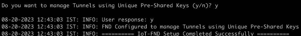 |
|
Step 3 |
On entering "y", FND is configured with PSK. FND updates the Preferences table by setting the property com.cisco.cgms.pnp.tunnelMgmtUsingPsk as True. By default, this property is False. |
Generating PSK
A unique pre-shared key is generated when you import a device through CSV or NB API. The pre-shared key is a 15-character alphanumeric string which is unique and generated randomly for each device. The generated key is encrypted and stored in the database for each router. For more information on tunnel management with PSK, see Workflow for Tunnel Management with PSK.
Default Templates
The following default templates are available for the tunnel management.
Router Tunnel Addition Template
There are two default router addition templates available for authentication. Based on the configuration settings in setupCgms.sh, the default template is selected to manage tunnels using PSK or not.
A sample template for FlexVPN and DMVPN tunnel configuration is given below.
Note |
By default, the peer name is set to her-tunnel in crypto ikev2 keyring FlexVPN_Keyring and Flexvpn_ikev2_profile. Configure the peer name to match the name that is given in identity local key-id in the HER configuration. |
<#-- This template only supports FARs running IOS. -->
<#if !far.isRunningIos()>
  ${provisioningFailed("FAR is not running IOS")}
</#if>

<#--
  For FARs running IOS configure a FlexVPN client in order to establish secure
  communications to the HER. This template expects that the HER has been
  appropriately pre-configured as a FlexVPN server.
-->
<#if far.isRunningIos()>
  <#assign sublist=far.eid?split("+")[0..1]>
  <#assign sn=sublist[1]>
  <#--
    Configure a Loopback0 interface for the FAR.
  -->
  interface Loopback0
    <#--
      If the loopback interface IPv4 address property has been set on the CGR
      then configure the interface with that address. Otherwise obtain an
      address for the interface now using DHCP.
    -->
    <#if far.loopbackV4Address??>
      <#assign loopbackIpv4Address=far.loopbackV4Address>
    <#elseif far.isIPAMForLoopbackSelected()??>
      <#assign loopbackIpv4Address=far.IPAMForLoopbackIpv4()>
    <#else>
      <#--
        Obtain an IPv4 address that can be used to for this FAR's Loopback
        interface. The template API provides methods for requesting a lease from
        a DHCP server. The IPv4 address method requires a DHCP client ID and a link
        address to send in the DHCP request. The 3rd parameter is optional and
        defaults to "IoT-FND". This value is sent in the DHCP user class option.
        The API also provides the method "dhcpClientId". This method takes a DHCPv6
        Identity association identifier (IAID) and a DHCP Unique IDentifier (DUID)
        and generates a DHCPv4 client identifier as specified in RFC 4361. This
        provides some consistency in how network elements are identified by the
        DHCP server.
      -->
      <#assign loopbackIpv4Address=far.ipv4Address(dhcpClientId(far.enDuid,0),far.dhcpV4LoopbackLink).address>
    </#if>
    ip address ${loopbackIpv4Address} 255.255.255.255
    <#--
      If the loopback interface IPv6 address property has been set on the CGR
      then configure the interface with that address. Otherwise obtain an
      address for the interface now using DHCP.
    -->
    <#if far.loopbackV6Address??>
      <#assign loopbackIpv6Address=far.loopbackV6Address>
    <#elseif far.isIPAMForLoopbackSelected()??>
      <#assign loopbackIpv6Address=far.IPAMForLoopbackIpv6()>
    <#else>
      <#--
        Obtain an IPv6 address that can be used to for this FAR's loopback
        interface. The method is similar to the one used for IPv4, except clients
        in DHCPv6 are directly identified by their DUID and IAID. IAIDs used for
        IPv4 are separate from IAIDs used for IPv6, so we can use zero for both
        requests.
      -->
      <#assign loopbackIpv6Address=far.ipv6Address(far.enDuid,0,far.dhcpV6LoopbackLink).address>
    </#if>
    ipv6 address ${loopbackIpv6Address}/128
  exit

  <#--
    Default to using FlexVPN for the tunnel configuration of FARs running IOS.
  -->
 <#if (far.useFlexVPN!"true") = "true">
    <#--
      IPv4 ACL which specifies the route(s) FlexVPN will push to the HER.
      We want the HER to know the route to the CGR's loopback interface.
    -->
    ip access-list standard FlexVPN_Client_IPv4_LAN
      permit ${loopbackIpv4Address}
    exit

    <#--
      IPv6 ACL which specifies the route(s) FlexVPN will push to the HER.
      We want the HER to know the route to the CGR's loopback interface.
      If a mesh has been configured on this CGR we want the HER to know the route to the mesh.
    -->
    ipv6 access-list FlexVPN_Client_IPv6_LAN
      <#if far.meshPrefix??>
        permit ipv6 ${far.meshPrefix}/64 any
      </#if>
      sequence 20 permit ipv6 host ${loopbackIpv6Address} any
    exit

    <#--
      FlexVPN authorization policy that configures FlexVPN to push the CGR LAN's
      specified in the ACLs to the HER during the FlexVPN handshake.
    -->
    crypto ikev2 authorization policy FlexVPN_Author_Policy
      route set access-list FlexVPN_Client_IPv4_LAN
      route set access-list ipv6 FlexVPN_Client_IPv6_LAN
      route set interface
    exit

    crypto ikev2 proposal FlexVPN_IKEv2_Proposal
      encryption aes-cbc-256
      group 14
      integrity sha256
    exit
    crypto ikev2 policy FLexVPN_IKEv2_Policy
      proposal FlexVPN_IKEv2_Proposal
    exit

    <#-- FlexVPN authorization policy is defined locally. -->
    aaa authorization network FlexVPN_Author local

    crypto ikev2 keyring FlexVPN_Keyring
      peer her-tunnel
        address ${far.ipsecTunnelDestAddr1}
        identity key-id her-tunnel
        pre-shared-key ${far.mgmtVpnPsk}
      exit
    exit

    crypto ikev2 profile FlexVPN_IKEv2_Profile
      match identity remote key-id her-tunnel
      identity local fqdn ${sn}.cisco.com
      authentication remote pre-share
      authentication local pre-share
      keyring local FlexVPN_Keyring
      dpd 120 3 periodic
      aaa authorization group psk list FlexVPN_Author FlexVPN_Author_Policy
    exit

    <#--
      If the headend router is an ASR then use a different configuration for the
      transform set as some ASR models are unable to support the set we'd prefer
      to use.
    -->
    <#if her.pid?contains("ASR")>
      crypto ipsec transform-set FlexVPN_IPsec_Transform_Set esp-aes esp-sha-hmac
        mode tunnel
      exit
    <#else>
      crypto ipsec transform-set FlexVPN_IPsec_Transform_Set esp-aes esp-sha256-hmac
        mode tunnel
      exit
    </#if>

    crypto ipsec profile FlexVPN_IPsec_Profile
      set ikev2-profile FlexVPN_IKEv2_Profile
      set pfs group14
      set transform-set FlexVPN_IPsec_Transform_Set
    exit

    <#assign wanInterface=far.interfaces(far.tunnelSrcInterface1!"Cellular")>
    interface Tunnel0
      description IPsec tunnel to ${her.eid}
      ip unnumbered loopback0
      ipv6 unnumbered loopback0
      tunnel destination dynamic
      tunnel protection ipsec profile FlexVPN_IPsec_Profile
      tunnel source ${wanInterface[0].name}
    exit

    <#if !(far.ipsecTunnelDestAddr1??)>
      ${provisioningFailed("FAR property ipsecTunnelDestAddr1 must be set to the destination address to connect this FAR's FlexVPN tunnel to")}
    </#if>
    crypto ikev2 client flexvpn FlexVPN_Client
      peer 1 ${far.ipsecTunnelDestAddr1}
      client connect Tunnel0
    exit
    ip http secure-client-auth
    no ip http tls-version TLSv1.2
  <#else>
    <#--
      Configure the tunnel using DMVPN.
    -->
    router eigrp 1
      network ${loopbackIpv4Address}
    exit
    ipv6 router eigrp 2
      no shutdown
    exit
    interface Loopback0
      ipv6 eigrp 2
    exit
    crypto ikev2 proposal DMVPN_IKEv2_Proposal
      encryption aes-cbc-256
      group 14
      integrity sha256
    exit
    crypto ikev2 policy DMVPN_IKEv2_Policy
      proposal DMVPN_IKEv2_Proposal
    exit
    crypto ikev2 keyring DMVPN_Keyring
      peer her-tunnel
        address ${far.ipsecTunnelDestAddr1}
        identity key-id her-tunnel
        pre-shared-key ${far.mgmtVpnPsk}
      exit
    exit
    crypto ikev2 profile DMVPN_IKEv2_Profile
      match identity remote key-id her-tunnel
      identity local fqdn ${sn}.cisco.com
      authentication remote pre-share
      authentication local pre-share
      keyring local DMVPN_Keyring
      dpd 120 3 periodic
    exit
    <#--
      If the headend router is an ASR then use a different configuration for the
      transform set as some ASR models are unable to support the set we'd prefer
      to use.
    -->
    <#if her.pid?contains("ASR")>
      crypto ipsec transform-set DMVPN_IPsec_Transform_Set esp-aes esp-sha-hmac
        mode tunnel
      exit
    <#else>
      crypto ipsec transform-set DMVPN_IPsec_Transform_Set esp-aes 256 esp-sha256-hmac
        mode tunnel
      exit
    </#if>
    crypto ipsec profile DMVPN_IPsec_Profile
      set ikev2-profile DMVPN_IKEv2_Profile
      set pfs group14
      set transform-set DMVPN_IPsec_Transform_Set
    exit
    <#if !(far.nbmaNhsV4Address??)>
      ${provisioningFailed("FAR property nbmaNhsV4Address has not been set")}
    </#if>
    <#if !(far.nbmaNhsV6Address??)>
      ${provisioningFailed("FAR property nbmaNhsV6Address has not been set")}
    </#if>
    <#assign wanInterface=far.interfaces(far.tunnelSrcInterface1!"Cellular")>
    interface Tunnel0
      <#assign lease=far.ipv4Address(dhcpClientId(far.enDuid,1),far.dhcpV4TunnelLink)>
      ip address ${lease.address} ${lease.subnetMask}
      ip nhrp map ${far.nbmaNhsV4Address} ${far.ipsecTunnelDestAddr1}
      ip nhrp map multicast ${far.ipsecTunnelDestAddr1}
      ip nhrp network-id 1
      ip nhrp nhs ${her.interfaces("Tunnel0")[0].v4.addresses[0].address}
      ipv6 address ${far.ipv6Address(far.enDuid,1,far.dhcpV6TunnelLink).address}/128
      ipv6 eigrp 2
      ipv6 nhrp map ${far.nbmaNhsV6Address}/128 ${far.ipsecTunnelDestAddr1}
      ipv6 nhrp map multicast ${far.ipsecTunnelDestAddr1}
      ipv6 nhrp network-id 1
      ipv6 nhrp nhs ${far.nbmaNhsV6Address}
      tunnel mode gre multipoint
      tunnel protection ipsec profile DMVPN_IPsec_Profile
      tunnel source ${wanInterface[0].name}
    exit
    router eigrp 1
      network ${lease.address}
    exit
  </#if>
</#if>
HER Tunnel Addition Template
Similar to Router Tunnel Addition templates, there are two default HER Tunnel Addition templates available. Based on the configuration settings in setupCgms.sh, the default template is selected to manage tunnels using PSK or not.
The following commands are pushed to HER for every router during device on-boarding (PnP). The configurations are added to a queue which are processed by a configurable number of threads and pushed to HER.
Note |
Ensure that the keyring name mentioned in "crypto ikev2 keyring FlexVPN_Keyring" and "FlexVPN_IKEv2_Profile" match the HER keyring name. |
per-Router HER Config

<#-- This template only supports HERs running IOS or IOS XE. -->
<#if !her.isRunningIos() && !her.isRunningIosXe()>
  ${provisioningFailed("HER is not running IOS or IOS XE")}
</#if>

<#if far.isRunningIos()>
  <#assign sublist=far.eid?split("+")[0..1]>
  <#assign sn=sublist[1]>

  crypto ikev2 keyring FlexVPN_Keyring
    peer ${sn}
      identity fqdn ${sn}.cisco.com
      pre-shared-key ${far.mgmtVpnPsk}
   exit
  exit
</#if>
Router Bootstrap Configuration Template
Note |
For SUDI authentication, you must use cgna initiator profile as the tunnel profile. |
Note |
Based on the device types, the following ports are used:
|
A sample router bootstrap configuration template:
<#assign sublist=far.eid?split("+")[0..1]>
<#assign pid=sublist[0]>
<#assign sn=sublist[1]>

hostname ${sn}
!
aaa new-model
!
!
aaa authentication login default local
aaa authorization exec default local
!
aaa session-id common
aaa password restriction
!
!
!
!
ip host fnd.iot.cisco.com <fnd ip address>
ip host tps.iot.cisco.com <tps ip address>
ip domain name cisco.com
!
password encryption aes
!
!
archive
  path bootflash:archive/
maximum 8
!
!
!
!
username admin privilege 15 password <router password>
!
!
no cdp run
!
!
!
!
interface Loopback999
 ip address <ip address for the interface> 255.255.255.255
!
!
ip forward-protocol nd
!
no ip http server
ip http tls-version TLSv1.2
ip http authentication aaa login-authentication default
ip http secure-server
ip http secure-port 443
ip http max-connections 5
ip http timeout-policy idle 600 life 86400 requests 3
ip http client connection timeout 5
ip http client connection retry 5
ip http client source-interface lo0
ip http client secure-trustpoint CISCO_IDEVID_SUDI

ip ssh time-out 60
ip ssh authentication-retries 2
crypto key generate rsa
ip ssh version 2
!
ipv6 unicast-routing
!
control-plane
!
!
line con 0
length 0
transport preferred none
escape-character 3
stopbits 1

!

line vty 6 15
session-timeout 10
exec-timeout 5 0
session-limit 2
transport input ssh
!
wsma agent exec
profile exec
!
wsma agent config
profile config
!
!wsma agent filesys
!
!wsma agent notify
!
!
wsma profile listener exec
transport https path /wsma/exec
!
wsma profile listener config
transport https path /wsma/config

event manager directory user policy "flash:/managed/scripts"
event manager policy no_config_replace.tcl type system authorization bypass
!
!
cgna gzip
!
!
cgna initiator-profile cg-nms-tunnel
 add-command show hosts | format flash:/managed/odm/cg-nms.odm
 add-command show interfaces | format flash:/managed/odm/cg-nms.odm
 add-command show version | format flash:/managed/odm/cg-nms.odm
 add-command show ipv6 dhcp | format flash:/managed/odm/cg-nms.odm
 add-command show ipv6 interface | format flash:/managed/odm/cg-nms.odm
 callhome-url https://tps.iot.cisco.com:9120/cgna/ios/config
 execution-url https://<ip address of Loopback999 interface>:443/wsma/config
 interval 10
 gzip
 post-commands
 active
ACL Configuration (Optional)
You can include ACL configuration in this template for additional security.
A sample ACL configuration:
access-list 10 permit <IP address of TPS>
access-list 10 deny any

interface gigabitEthernet 0/0/0
ip access-group 10 in
exit
Note |
In the above sample configuration, the communication with FAR is only through IP address of TPS until the tunnel is established. |
After the tunnel is established, you can remove the ACL configuration.
To remove the ACL configuration, add the following commands in the Router Tunnel Addition Template:
no access-list 10
interface gigabitEthernet 0/0/0
no ip access-group 10 in
exit
HER Tunnel FlexVPN Configuration Template
A sample HER tunnel FlexVPN configuration template:
version 17.12
service timestamps debug datetime msec
service timestamps log datetime msec
platform qfp utilization monitor load 80
platform punt-keepalive disable-kernel-core
platform sslvpn use-pd
platform console virtual
!
hostname xxxxxxx
!
boot-start-marker
boot-end-marker
!
!
aaa new-model
!
!
aaa authentication login default local
aaa authentication login AUTH local
aaa authorization exec default local
aaa authorization network FlexVPN_Author local
aaa authorization network NET local !
!
aaa session-id common
clock timezone IST 0 0
!
!

ip domain name cisco.com
!
!
!
login on-success log
!
!
subscriber templating
vtp version 1
!
!
!
!
!
!
multilink bundle-name authenticated
!
!
!
!
!
!
!
!
crypto pki trustpoint TP-self-signed-141726200
 enrollment selfsigned
 subject-name cn=IOS-Self-Signed-Certificate-141726200
 revocation-check none
 rsakeypair TP-self-signed-141726200
 hash sha256
!
crypto pki trustpoint SLA-TrustPoint
 enrollment pkcs12
 revocation-check crl
 hash sha256
!
!
crypto pki certificate chain TP-self-signed-141726200
 certificate self-signed 01
  xxxxxxxxxxxxxxxxxxxxxxxxxxxxxxxxxxxxxxxxxxxxxxxxxxxxxx
  xxxxxxxxxxxxxxxxxxxxxxxxxxxxxxxxxxxxxxxxxxxxxxxxxxxxxx
  xxxxxxxxxxxxxxxxxxxxxxxxxxxxxxxxxxxxxxxxxxxxxxxxxxxxxx
  xxxxxxxxxxxxxxxxxxxxxxxxxxxxxxxxxxxxxxxxxxxxxxxxxxxxxx
  xxxxxxxxxxxxxxxxxxxxxxxxxxxxxxxxxxxxxxxxxxxxxxxxxxxxxx
  xxxxxxxxxxxxxxxxxxxxxxxxxxxxxxxxxxxxxxxxxxxxxxxxxxxxxx
  xxxxxxxxxxxxxxxxxxxxxxxxxxxxxxxxxxxxxxxxxxxxxxxxxxxxxx
  xxxxxxxxxxxxxxxxxxxxxxxxxxxxxxxxxxxxxxxxxxxxxxxxxxxxxx
  xxxxxxxxxxxxxxxxxxxxxxxxxxxxxxxxxxxxxxxxxxxxxxxxxxxxxx
  xxxxxxxxxxxxxxxxxxxxxxxxxxxxxxxxxxxxxxxxxxxxxxxxxxxxxx
  xxxxxxxxxxxxxxxxxxxxxxxxxxxxxxxxxxxxxxxxxxxxxxxxxxxxxx
  xxxxxxxxxxxxxxxxxxxxxxxxxxxxxxxxxxxxxxxxxxxxxxxxxxxxxx
  xxxxxxxxxxxxxxxxxxxxxxxxxxxxxxxxxxxxxxxxxxxxxxxxxxxxxx
  xxxxxxxxxxxxxxxxxxxxxxxxxxxxxxxxxxxxxxxxxxxxxxxxxxxxxx
  xxxxxxxxxxxxxxxxxxxxxxxxxxxxxxxxxxxxxxxxxxxxxxxxxxxxxx
  xxxxxxxxxxxxxxxxxxxxxxxxxxxxxxxxxxxxxxxxxxxxxxxxxxxxxx
  xxxxxxxxxxxxxxxxxxxxxxxxxxxxxxxxxxxxxxxxxxxxxxxxxxxxxx
  xxxxxxxxxxxxxxxxxxxxxxxxxxxxxxxxxxxxxxxxxxxxxxxxxxxxxx
  xxxxxxxxxxxxxxxxxxxxxxxxxxxxxxxxxxxxxxxxxxxxxxxxxxxxxx
  xxxxxxxxxxxxxx
        quit
crypto pki certificate chain SLA-TrustPoint
 certificate ca 01
  xxxxxxxxxxxxxxxxxxxxxxxxxxxxxxxxxxxxxxxxxxxxxxxxxxxxxx
  xxxxxxxxxxxxxxxxxxxxxxxxxxxxxxxxxxxxxxxxxxxxxxxxxxxxxx
  xxxxxxxxxxxxxxxxxxxxxxxxxxxxxxxxxxxxxxxxxxxxxxxxxxxxxx
  xxxxxxxxxxxxxxxxxxxxxxxxxxxxxxxxxxxxxxxxxxxxxxxxxxxxxx
  xxxxxxxxxxxxxxxxxxxxxxxxxxxxxxxxxxxxxxxxxxxxxxxxxxxxxx
  xxxxxxxxxxxxxxxxxxxxxxxxxxxxxxxxxxxxxxxxxxxxxxxxxxxxxx
  xxxxxxxxxxxxxxxxxxxxxxxxxxxxxxxxxxxxxxxxxxxxxxxxxxxxxx
  xxxxxxxxxxxxxxxxxxxxxxxxxxxxxxxxxxxxxxxxxxxxxxxxxxxxxx
  xxxxxxxxxxxxxxxxxxxxxxxxxxxxxxxxxxxxxxxxxxxxxxxxxxxxxx
  xxxxxxxxxxxxxxxxxxxxxxxxxxxxxxxxxxxxxxxxxxxxxxxxxxxxxx
  xxxxxxxxxxxxxxxxxxxxxxxxxxxxxxxxxxxxxxxxxxxxxxxxxxxxxx
  xxxxxxxxxxxxxxxxxxxxxxxxxxxxxxxxxxxxxxxxxxxxxxxxxxxxxx
  xxxxxxxxxxxxxxxxxxxxxxxxxxxxxxxxxxxxxxxxxxxxxxxxxxxxxx
  xxxxxxxxxxxxxxxxxxxxxxxxxxxxxxxxxxxxxxxxxxxxxxxxxxxxxx
  xxxxxxxxxxxxxxxxxxxxxxxxxxxxxxxxxxxxxxxxxxxxxxxxxxxxxx
  xxxxxxxxxxxxxxxxxxxxxxxxxxxxxxxxxxxxxxxxxxxxxxxxxxxxxx
  xxxxxxxxxxxxxxxxxxxxxxxxxxxxxxxxxxxxxxxxxxxxxxxxxxxxxx
  xxxxxxxxxxxxxxxxxxxxxxxxxxxxxxxxxxxxxxxxxxxxxxxxxxxxxx
  xxxxxxxxxxxxxxxxxxxxxxxxxxxxxxxxxxxxxxxxxxxxxxxxxxxxxx
  xxxxxxxxxxxxxx
        quit
!
!
!
!
!
!
!
!
!
license udi pid C8000V sn 9OA9SRYYZVZ
license boot level network-advantage addon dna-advantage
memory free low-watermark processor 203066
diagnostic bootup level minimal
!
!
spanning-tree extend system-id
!
!
!
username xxxxxx privilege 15 password 0 xxxxxxxxxx
!
redundancy
!
crypto ikev2 authorization policy FlexVPN_Author_Policy
 route set interface
 route set access-list FlexVPN_Client_Default_IPv4_Route
!
crypto ikev2 redirect client
crypto ikev2 proposal FlexVPN_IKEv2_Proposal
 encryption aes-cbc-256
 integrity sha256
 group 14
!
crypto ikev2 policy FLexVPN_IKEv2_Policy
 proposal FlexVPN_IKEv2_Proposal
!
crypto ikev2 keyring FlexVPN_Keyring
 peer far1_sn
  identity fqdn far1_sn.cisco.com
  pre-shared-key GE39jy3Qe8Uo1Ro
!
 peer far2_sn
  identity fqdn far2_sn.cisco.com
  pre-shared-key LE73pj2Pk8Jh8Ui
!
 peer far3_sn
  identity fqdn far3_sn.cisco.com
  pre-shared-key FB86gn4Ns1Fm1Dj
!
!
!
crypto ikev2 profile FlexVPN_IKEv2_Profile
 match identity remote fqdn domain cisco.com
 identity local key-id CLUSTER-2
 authentication remote pre-share
 authentication local pre-share
 keyring local FlexVPN_Keyring
 dpd 120 3 periodic
 aaa authorization group psk list FlexVPN_Author FlexVPN_Author_Policy
 virtual-template 1 !
!
!
!
!
!
!
!
!
!
!
crypto isakmp invalid-spi-recovery
!
!
crypto ipsec transform-set FlexVPN_IPsec_Transform_Set esp-aes esp-sha256-hmac
 mode transport
!
crypto ipsec profile FlexVPN_IPsec_Profile
 set transform-set FlexVPN_IPsec_Transform_Set
 set pfs group14
 set ikev2-profile FlexVPN_IKEv2_Profile
 responder-only !
!
!
!
!
!
!
!
!
!
interface Loopback0
 ip address xx.xx.xx.xx 255.255.255.255
!
interface GigabitEthernet1
 ip address xx.xx.xx.xx 255.255.255.128
 negotiation auto
 no mop enabled
 no mop sysid
!
interface GigabitEthernet2
 ip address xx.xx.xx.xx 255.255.255.0
 negotiation auto
 no mop enabled
 no mop sysid
!
interface GigabitEthernet3
 no ip address
 shutdown
 negotiation auto
 no mop enabled
 no mop sysid
!
interface Virtual-Template1 type tunnel
 ip unnumbered Loopback0
 ip mtu 1200
 ip tcp adjust-mss 1240
 tunnel source GigabitEthernet2
 tunnel protection ipsec profile FlexVPN_IPsec_Profile
!
ip default-gateway xx.xx.xx.xx
ip forward-protocol nd
!
ip http server
ip http authentication local
ip http secure-server
ip http secure-active-session-modules none
ip http active-session-modules none
ip dns server
ip ssh bulk-mode 131072 !
!
ip access-list standard FlexVPN_Client_Default_IPv4_Route
 10 permit any
!
!
!
!
!
!
!
control-plane
!
!
mgcp behavior rsip-range tgcp-only
mgcp behavior comedia-role none
mgcp behavior comedia-check-media-src disable
mgcp behavior comedia-sdp-force disable !
mgcp profile default
!
!
!
!
!
!
line con 0
 stopbits 1
line aux 0
line vty 0 4
 password cisco123
 transport input ssh
!
!
netconf legacy
netconf ssh
!
!
!
!
!
End
HER Tunnel Deletion Template
Note |
Ensure that the keyring name mentioned in "crypto ikev2 keyring FlexVPN_Keyring" and "FlexVPN_IKEv2_Profile" match the HER keyring name. |
A sample HER tunnel deletion template for HERs on Cisco IOS and Cisco IOS-XE.
Remove Router PSK config from HER
<#-- This template only supports HERs running IOS or IOS XE. -->
<#if !her.isRunningIos() && !her.isRunningIosXe()>
  ${provisioningFailed("HER is not running IOS or IOS XE")}
</#if>

<#if far.isRunningIos()>
  <#assign sublist=far.eid?split("+")[0..1]>
  <#assign sn=sublist[1]>

  crypto ikev2 keyring FlexVPN_Keyring
    no peer ${sn}
  exit
</#if>
Configuring ZTD Properties
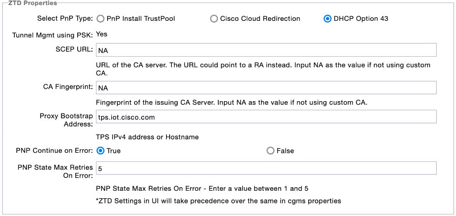
The ZTD Properties section allows you to manage the device certificates with either SUDI or a CA server. On configuring FND with PSK for tunnel management, by default, the devices use SUDI certificate for the communication with FND. However, if you want to manage using a CA server, provide details in the SCEP URL and CA Fingerprint fields ().
Workflow for Tunnel Management with PSK
This section provides the workflow for tunnel management with PSK.
Staging
To stage the router with FND TPS URL:
Procedure
|
Step 1 |
Configuring FND for PSK-based tunnels differ for each deployment as given below. For Bare Metal or Virtual Machine deployments with Oracle DB, run the setupCgms.sh script before starting the cgms service for configuration with PSK based tunnel management. In these deployments, either the default Tunnel Provisioning group or a newly created Tunnel Provisioning group is used for PSK based tunnel management. For Virtual Machine deployment with Postgres DB, as the cgms service will already be running on OVA installation, the cgms service is restarted using the steps below while executing setupCgms.sh script. In this deployment, user creates a new Tunnel Provisioning group for PSK based tunnel management configuration. |
|
Step 2 |
Generate a public CA signed server certificate for TPS and FND using the existing CSR generation workflow. |
|
Step 3 |
Configure FlexVPN on HER. For more information on the configuration, see HER Tunnel FlexVPN Configuration Template. |
|
Step 4 |
Import the device to FND through CSV or NB API.
FND generates a unique pre-shared key for each device and adds the generated key to the device property while storing in the database. |
|
Step 5 |
Stage the router with FND TPS URL using DHCP option 43 or PnP Install Trustpool / Cloud Redirection for PnP. |
What to do next
PnP Bootstrapping
To bootstrap a device:
Before you begin
Procedure
|
Step 1 |
Field area router (PnP agent) calls FND (through FND TPS). |
||
|
Step 2 |
FND pushes the Trust Anchor (root certificate) to the device. |
||
|
Step 3 |
To push the FAR PSK to the associated HER, a new state CONFIGURING_HEADEND is added in PnP.
|
||
|
Step 4 |
FND pushes the Bootstrap template to the device, which includes a tunnel creation profile and loopback IP configuration. For more information on the default templates, see Default Templates. |
||
|
Step 5 |
On successful completion of PnP, the device status is marked as Bootstrapped in FND. |
What to do next
Tunnel Provisioning
To push the PSK configuration to the router:
Before you begin
Procedure
|
Step 1 |
Field area router calls FND (through FND TPS). Authentication based on mTLS:
|
|
Step 2 |
FND pushes the PSK along with other tunnel configurations present in the Router Tunnel Addition template to the router and activates the registration profile.
|
What to do next
Device Configuration
To push device configuration to the router:
Before you begin
Complete the following workflows:
Procedure
|
Step 1 |
Field area router calls FND (through IPsec). Authentication based on mTLS:
|
|
Step 2 |
FND pushes the device configuration present in the Configuration Template to the router. |
|
Step 3 |
On successful completion, the device is marked as UP in FND. |
Pushing PSK Configuration to HER Cluster
This section explains the steps that are required to push the PSK configuration to HER in the cluster.
Pushing PSK Configuration to Existing HERs in the Cluster
Use the following steps to push the PSK configuration to the existing HERs in the cluster, which are added to the cluster before the tunnel establishment.
Procedure
|
Step 1 |
Import all HERs in the cluster to FND and have them managed with the device status as UP. |
|
Step 2 |
For FND to be aware of the list of HERs in a cluster, add the list of HER eids separated by comma in the tunnelhereid property. |
|
Step 3 |
On receiving a PnP request from a FAR, the tunnelhereid property is checked to get the list of HERs in the cluster. |
|
Step 4 |
PSK configuration is pushed to each HER in the cluster.
|
Pushing PSK Configuration to New HER in the Cluster
Use the following steps to push the PSK configuration to a new HER, which is added to the cluster after the tunnel is established.
Note |
The addition or removal of HERs from the tunnelHerEid list is added to a table named pending_tunnel_her_in_cluster in the DB. FND has a separate thread that runs every five minutes to pick up the entries from the table and based on the add_peer flag, it either pushes the PSK configuration or removes the PSK configuration to or from the HER. |
Procedure
|
Step 1 |
Import the new HER to FND and have it managed with the device status as UP. |
||
|
Step 2 |
Update the FAR using Change Device Properties to add the new HER to the tunnelhereid property list.
|
||
|
Step 3 |
The PSK configuration is pushed to the new HER added to the tunnelHerEid property list and an associated event (success or failure) is generated on the FAR. If any HER is removed from the tunnelHerEid property, then the PSK configuration of that HER is removed and an event is generated for successful configuration removal on the HER. |
Viewing Events
This section provides information on the events generated on FAR and HER when pushing and removing PSK tunnel configuration.
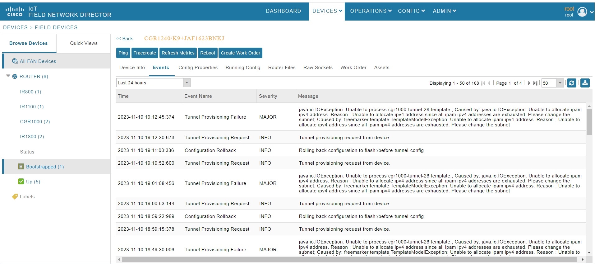
Viewing FAR Events
Use the following steps to view the events generated when pushing PSK tunnel configuration on HER during FAR onboarding.
-
Choose .
-
Select the device on the right pane. The Device Info page appears.
-
Click the Events tab to view the following events.
Event Name
Severity Level
Description
PSK Tunnel Configuration Pushed to HER
INFO
On successful completion of pushing PSK tunnel configuration on HER.
PSK Tunnel Configuration on HER Failed
Major
On failure to push the PSK tunnel configuration on HER.
Viewing HER Events
Use the following steps to view the events generated when removing the PSK tunnel configuration from HER and FAR during FAR decommissioning.
-
Choose .
-
Select the HER on the right pane. The Device Info page appears.
-
Click the Events tab to view the following events.
Event Name
Severity Level
Description
HER PSK Tunnel Configuration Removed for FAR
INFO
On successful removal of PSK configuration from HER.
HER PSK Tunnel Configuration Removal Failure for FAR
Major
On failure to remove the PSK configuration from HER.
Note
In this case, you should remove the PSK configuration from HER manually.
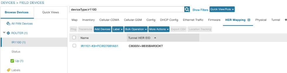
HER Mapping with FAR
Use the following steps to view the HERs associated with the FAR.
-
Choose .
-
Select the device on the left pane.
-
Click the HER Mapping tab on the right pane.
-
The HER associated with the device appears under the Tunnel HER EID column.
Use the filter option to search for HERs based on HER EID.
Decommissioning a Device
Whenever there is a device decommissioning, FND automatically removes the PSK configuration from HER using the HER deletion template which is available by default. If the HER is in a cluster, FND removes the PSK configuration from all HERs.
For information on HER deletion template, see HER Tunnel Deletion Template.
For information on events generated during PSK configuration removal from HER, see Viewing HER Events.


 Feedback