Setting Up Factory Default Device Using WebUI

Quick Setup Wizard allows you perform the basic router configuration. To configure the router:


Note


Before you access the WebUI, you need to have the basic configuration on the device.


Procedure


Step 1

Ensure that the router is in the factory fresh mode. If the router is not in the factory fresh mode, use the write erase option to erase all the configuration from the router.

Step 2

Ensure that the following basic configuration is available on the device.

!
!
ip dhcp excluded-address 192.168.1.1 192.168.1.5
!
ip dhcp pool WEBUIPool
network 192.168.1.0 255.255.255.0
default-router 192.168.1.1
dns-server 192.168.1.1
!
!
username webui privilege 15 secret cisco
!
interface Vlan1 
ip address 192.168.1.1 255.255.255.0
ip nat inside
no shutdown
!

Step 3

Connect the PC to any of the switch port which is the member of VLAN1. By default, all the ports will be the member of VLAN1 and the PC recieves the IP address from the pool WEBUIPool.

Step 4

After your PC receives the IP address, launch the browser, type https://192.168.1.1/webui/#/dayZeroRouting or enter http://192.168.1.1/webui/#/dayZeroRouting.

Step 5

Enter the default username (webui) and default password (cisco).


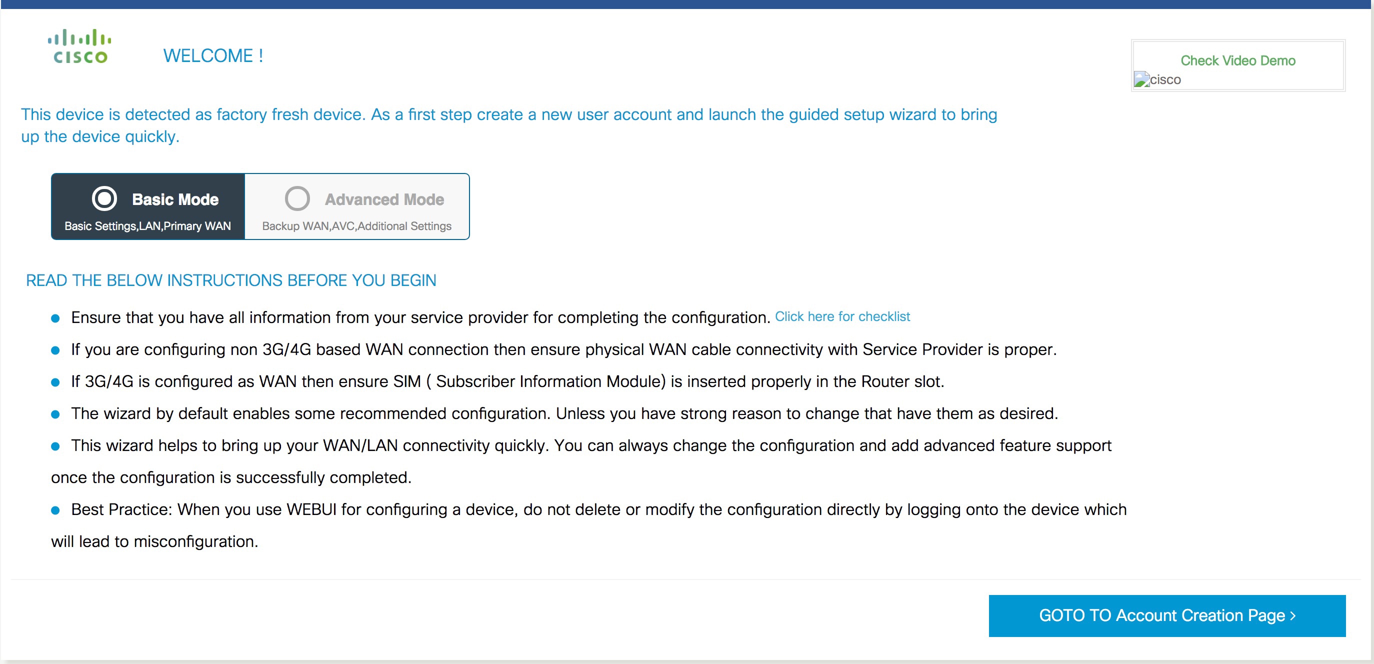
Using Basic or Advanced Mode Setup Wizard

To configure the router using the basic or advanced mode setup:

Procedure


Step 1

Choose the Basic Mode or Advanced Mode and click Go To Account Creation Page.

Step 2

Enter the username and password. Reenter the password to confirm.

Step 3

Click Create and Launch Wizard.

Step 4

Enter the device name and domain name.

Step 5

Select the appropriate time zone from the Time Zone drop-down list.

Step 6

Select the appropriate date and time mode from the Date and Time drop-down list.
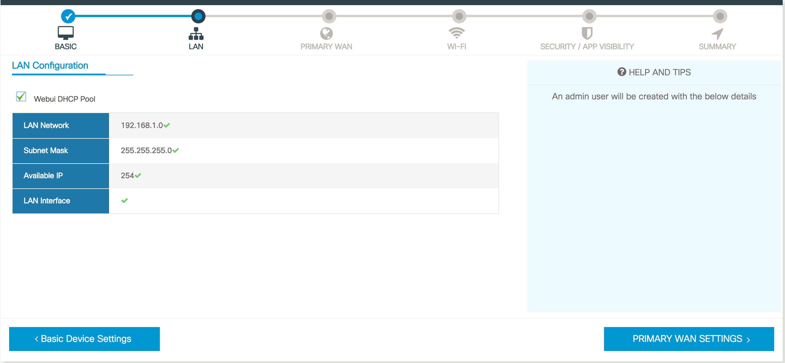
Step 7

Click LAN Settings.

Steps to use the Basic or Advanced Mode Setup Wizard


Configure LAN Settings

Procedure


Step 1

Choose the Web DHCP Pool/DHCP Pool name or the Create and Associate Access VLAN option.

  1. If you choose the Web DHCP Pool, specify the following:

    Pool Name—Enter the DHCP Pool Name. Network—Enter network address and the subnet mask.
  2. If you choose the Create and Associate Access VLAN option, specify the following:

    Access VLAN—Enter the Access VLAN identification number. The range is from 1 to 4094. Network—Enter the IP address of the VLAN. Management Interfaces—Select the interface and move to the selected list box using the right and left arrows. You can also double click or drag and drop to move the interface to the selected list box.

Step 2

Click Primary WAN Settings.

Steps to configure LAN settings

Configure Primary WAN Settings

Procedure


Step 1

Select the primary WAN type. You can configure Serial, 3G/4G, Ethernet, or Broadband (xDSL) as primary WAN depending on the WAN types supported by the router.

Step 2

Select the interface from the drop-down list.

Step 3

Check the Get DNS Server info directly from ISP check box to get the DNS server information directly from the service provider. You can also manually enter the Primary DNS and Secondary DNS.

Step 4

Check the Get IP automatically from ISP check box to get the IP address information directly from the service provider. You can also manually enter the IP address and subnet mask.

Step 5

Check the Enable NAT check box to enable NAT. It is recommended to enable NAT.

Step 6

Check the Enable PPPOE check box to enable PPPoE. If you have enabled PPPoE, select the required authentication mode. The options are: PAP and CHAP.

Step 7

Enter the username and password provided by the service provider.

Step 8

Click Security / APP Visibility WAN Settings.


Configure Secondary WAN Settings

For advanced configuration, you should configure the secondary WAN connection.

Procedure


Step 1

Select the secondary WAN type. You can configure Serial, 3G/4G, Ethernet, or Broadband (xDSL) as a secondary WAN depending on the WAN types supported by the router.

Step 2

Select the interface from the drop-down list.

Step 3

Check the Get DNS Server info directly from ISP check box to get the DNS server information directly from the service provider. You can also manually enter the Primary DNS and Secondary DNS.

Step 4

Check the Get IP automatically from ISP check box to get the IP address information directly from the service provider. You can also manually enter the IP address and subnet mask.

Step 5

Check the Enable NAT check box to enable NAT. It is recommended to enable NAT.

Step 6

Check the Enable PPPOE check box to enable PPPoE. If you have enabled PPPoE, select the required authentication mode. The options are PAP and CHAP.

Step 7

Enter the username and password provided by the service provider.

Step 8

Click Security / APP Visibility WAN Settings.


Configure Security Settings

Procedure


Step 1

Check the Enable Cisco Recommended Security Settings check box to ensure that all passwords are not shown in plain text. The passwords are encrypted.

Step 2

Click Day 0 Config Summary.

Step 3

To preview the configuration, click CLI Preview to preview the configuration.

Step 4

Click Finish to complete the Day Zero setup.


Using Web User Interface for Day One Setup

To configure the Web user interface:

Before you begin

  • You need to configure at least 30 VTY lines on the device for the Web UI information to be displayed without errors.

  • You need a user with privilege 15 to access the configuration screens on Web UI. If the privilege is less than 15, you can access only the Dashboard and Monitoring screens on Web UI.

    To create a user account, use the username <username> privilege <privilege> password 0 <passwordtext>

    Device #configure terminal
    Device (config)# username <username> privilege <privilege> password 0 <passwordtext>

Procedure


Step 1

Configure the HTTP server. By default, the HTTP server configuration should be present on the device. Ensure the configuration by checking if the ip http server and ip http secure-server commands are present in the running configuration.

Device #configure terminal
Device (config)#ip http server
Device (config)#ip http secure-server

Step 2

Set up the authentication options to log into Web UI. You can use one of these methods to authenticate:

  1. You can authenticate using local database. To use a local database for Web UI authentication, ensure to have the ip http authentication local command in the running configuration. This command is preconfigured on the device. If the command is not present, configure the device as shown in this example:

    Device #configure terminal 
     Device (config)#ip http authentication local
    
  2. Authenticate using AAA options. To use AAA authentication for Web UI, ensure to configure ‘ip http authentication aaa’ on the device. Also, ensure that the required AAA server configuration is present on the device.

    Device #configure terminal
    Device (config)#ip http authentication local
     

Step 3

Launch the browser. In the address bar, type the IP address of the device. For a secure connection, type https://ip-address.

Step 4

Enter the default username (webui) and default password (cisco).

Step 5

Click Log In.


Monitor and Troubleshoot Device Plug and Play (PnP) Onboarding using WebUI

Table 1. Feature History

Feature Name

Release Information

Description

Monitor and Troubleshoot Device PnP Onboarding using WebUI

Cisco IOS XE Catalyst SD-WAN Release 17.5.1a

You can now monitor and troubleshoot your Day-0 device onboarding using WebUI through PnP onboarding. If the automated PnP onboarding fails, you can manually onboard your device.

A device can be automatically onboarded to Cisco vManage through either Zero Touch Provisioning (ZTP) or the Plug and Play (PnP) process. This section describes the procedure to monitor and troubleshoot device onboarding through the PnP method. This feature on WebUI enables you to monitor and troubleshoot the PnP onboarding process, and also see its real-time status. If this onboarding is stuck or fails, you can terminate the process and onboard your device manually.

Prerequisites

  • Your device (a computer that can run a web browser) running the WebUI and the device you are onboarding must be connected through an L2 switch port (NIM) on the device.
  • The DHCP client-identifier on your device must be set to string “webui”.
  • Your device must support Cisco SD-WAN Day-0 device onboarding on WebUI.

Troubleshoot Device PnP Onboarding

To troubleshoot device onboarding through PnP in controller mode:

  1. Enter the controller mode in WebUI:
    • Switching from autonomous mode to controller mode:

      Usually, when you boot your device for the first time it is in autonomous mode. Go to the URL https://192.168.1.1/webui/ and log in using the default credentials— webui/cisco. If your device supports Cisco SD-WAN Day-0 device onboarding on WebUI, you can switch to the controller mode by selecting Controller Mode. A dialogue box appears, asking if you want to continue. Click Yes. Your device reloads to switch to controller mode.

    • Booting your device in controller mode:

      If your device is already in the controller mode, you do not have to make any changes to the mode. Go to the URL https://192.168.1.1 or https://192.168.1.1/webui. If your device supports Cisco SD-WAN Day-0 device onboarding on WebUI, the URL is redirected to https://192.168.1.1/ciscosdwan/ and you can log in using the default credentials for Cisco IOS XE SD-WAN devices - admin/admin.


    Note


    If the device does not have start-up configuration at the time of PnP onboarding, the WebUI is enabled by default on supported devices.
  2. On the Welcome to Cisco SDWAN Onboarding Wizard page, click Reset Default Password.


    Note


    The default password of your Day-0 device is weak. Therefore, for a secure log in, you must reset the password when you first log in to the device on WebUI. The WebUI configuration is automatically deleted after the device is onboarded successfully. In rare cases where the template configuration for your device on Cisco vManage has the WebUI configuration, it is not deleted even after a successful device onboarding.
  3. You are redirected to the Device hardware and software details page. Enter your password and click Submit.

  4. The next page displays the onboarding progress and lists statuses of different components of the PnP Connect Portal and Cisco SD-WAN controllers. If the PnP IPv4 component fails, it indicates that the device PnP onboarding has failed.

    To view and download logs for the onboarding process, click the information icon on the right hand side of the SDWAN Onboarding Progress bar.

  5. If the automated PnP onboarding fails, click Terminate Automated Onboarding. This allows you to onboard your device manually.

  6. A dialogue box appears. To continue with the termination, click Yes. It might take a few minutes for the termination to complete.

  7. On the Bootstrap Configuration page click Select File and choose the bootstrap file for your device. This file can be either a generic bootstrap file (common platform-specific file) or a full configuration bootstrap file that you can download from Cisco SD-WAN Manager. This file must contain details such as the vBond number, UUID, WAN interface, root CA and configuration.

  8. Click Upload.

  9. After your file is successfully uploaded, click Submit.

  10. You can see the SDWAN Onboarding Progress page again with statuses of the Cisco SD-WAN controllers. To open the Controller Connection History table click the information icon on the right hand side of the SDWAN Control Connections bar. In this table you can see the state of your onboarded device. After the onboarding is complete, the state of your device changes to connect.