Installing the NCS1K-MD-64-C Module

This chapter explains how to install and operate the NCS1K-MD-64-C module.

Understanding NCS1K-MD-64-C

A new optical passive optical multiplexer and de-multiplexer module, NCS1K-MD-64-C, is introduced in Cisco NCS 2000 Series R12.1 and in Cisco NCS 1000 Series R7.3.1. The new optical module is based on Athermal Wave Guide (AWG) providing 64 channels at 75-GHz space covering the extended C-band of optical spectrum. The passive module allows you to transmit 400G ZR and 400G ZR+ wavelengths.

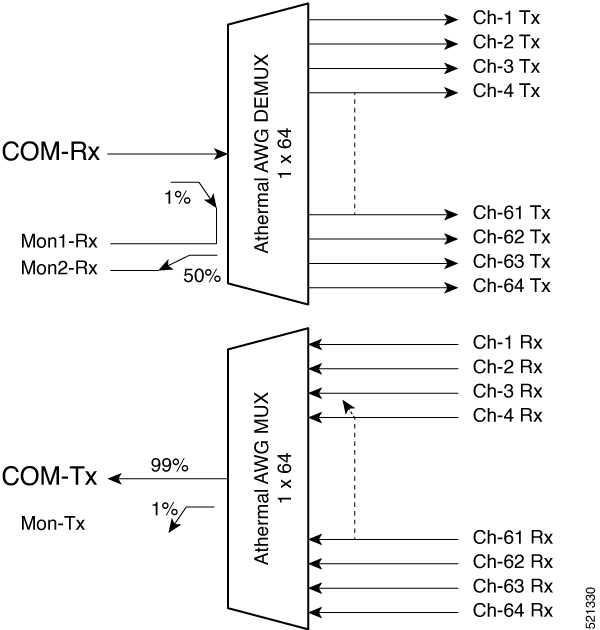
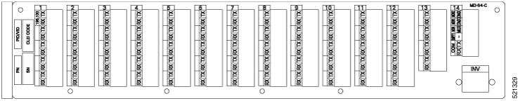
NCS1K-MD-64-C is a bidirectional unit that have the MUX and the DEMUX functions implemented as two different sections. This module fits into ETSI 300 mm and ANSI 450 mm racks.

Mutiplexer

  • 64 Channels AWG combines the signal coming from Chi-RX ports into the aggregated COM-TX port.

  • An integrated tap-coupler splits 1% of the aggregated signals toward MON-TX port for monitoring.

Demutiplexer

  • An integrated tap-coupler splits 1% of the aggregated signals coming from COM-RX port toward MON-TX port for monitoring.

  • 64 Channels AWG splits the aggregated signals into individual Chi-TX ports.

Figure 1. NCS1K-MD-64-C Optical Block Diagram
NCS1K-MD-64-C Optical Block Diagram
Figure 2. NCS1K-MD-64-C Faceplate
NCS1K-MD-64-C Faceplate

Port Label Descriptions

The following table lists the connection ports, description, and the type of connectors used for each port.

Table 1. Port Label Descriptions
Port Label Description Type of Connector
COM-TX Common output LC-UPC II
COM-RX Common input LC-UPC II
MON-TX Monitor output LC-UPC II
MON-RX1 Monitor input LC-UPC II
MON-RX2 Monitor input LC-UPC II

Optical Channel Grid

Table 2. Optical Channel Grid
Channel Number Frequency

1

196,100

2

196,025

3

195,95

4

195,875

5

195,8

6

195,725

7

195,65

8

195,575

9

195,5

10

195,425

11

195,35

12

195,275

13

195,2

14

195,125

15

195,05

16

194,975

17

194,9

18

194,825

19

194,75

20

194,675

21

194,6

22

194,525

23

194,45

24

194,375

25

194,3

26

194,225

27

194,15

28

194,075

29

194

30

193,925

31

193,85

32

193,775

33

193,7

34

193,625

35

193,55

36

193,475

37

193,4

38

193,325

39

193,25

40

193,175

41

193,1

42

193,025

43

192,95

44

192,875

45

192,8

46

192,725

47

192,65

48

192,575

49

192,5

50

192,425

51

192,35

52

192,275

53

192,2

54

192,125

55

192,05

56

191,975

57

191,9

58

191,825

59

191,75

60

191,675

61

191,6

62

191,525

63

191,45

64

191,375

Install Patch Panel

Procedure


Step 1

Mount the brackets on the patch panel.

  1. Place the mounting bracket flush against the patch panel.

  2. Align the mounting bracket screw holes against the patch panel screw holes.

  3. Insert the screws and tighten them.

  4. Repeat steps 1a through 1c to mount another bracket on the opposite side.

    Figure 3. Mounting the brackets on the 8-degree mesh patch panel module

    1

    Mounting bracket

    2

    Screw

Step 2

Install the patch panel on the appropriate rack equipment.

  1. Lift the patch panel to the desired position in the rack.

  2. Align the screw holes on the mounting brackets with the mounting holes in the rack.

  3. Insert the screws and tighten them.

Step 3

Establish grounding for the patch panel.

  1. Crimp a #14 AWG ground cable to the ground lug.

  2. Attach the ground lug to the patch panel.

    The ground points are present on the left and right rear side of the patch panel, as shown in the following figure.

    Figure 4. Grounding the 8-degree mesh patch panel module

    1

    Ground point

    2

    Ground lug

    3

    Lock washer

    4

    Pan head screw

  3. Tighten the lug using the screws.

  4. Terminate the other end of the ground cable either at the office ground point or the rack ground point.


Install and Route Fiber-Optic and USB Cables

All connectors are on the front of the NCS1K-MD-64-C module and are equipped with LC/UPC bulkhead adapters and with a USB Type A receptacle connector for inventory purpose. For port label description, see Port Label Descriptions. The LC-LC patch cords are used to connect the NCS1K-MD-64-C module to the patch panels.


Warning

Invisible laser radiation may be emitted from disconnected fibers or connectors. Do not stare into beams or view directly with optical instruments. Statement 1051


Caution

When connecting an optical fiber patch cord between the patch panel and the optical card ports in Cisco NCS 2000 Series, use the electrostatic discharge wristband supplied with NCS 2000 Series . Plug the wristband into the ESD jack on the lower right front side of NCS 2000.


Note

Always clean all fiber connectors thoroughly before making the connection with the mating adapter. Very small particles can permanently damage the end of the mating fiber inside the patch panel, which makes regular cleaning imperative. For cleaning instructions see "Clean Fiber-Optic Cable Connectors".

Caution

The NCS1K-MD-64-C module has LC/UPC bulkhead adapters for optical connections. Always use fiber-optic cables equipped with the corresponding (LC/UPC) connector type. Using any other type of connector results in damage to the connector or adapter, or both.


Procedure


Step 1

To connect the fibers as appropriate, perform the following:

  1. Remove the LC adapter cap from the LC-LC adapter of the NCS1K-MD-64-C module.

  2. Place the LC/UPC cable connector in front of the corresponding bulkhead adapter on the front panel of the NCS1K-MD-64-C module.

  3. Align the keyed ridge of the cable connector with the slot in the receiving adapter.

  4. Gently push the cable connector into the adapter until you hear a click, which indicates that the latching system is engaged.

  5. Route the cables through the left or right fiber holder clip.

  6. (Optional) Secure the fibers further by placing them into one or more adhesive clips. The adhesive clips can be placed on the fiber management plate as per the actual installation conditions.

  7. Place the extra fiber length of the two LC-LC patch cords used to connect the patch panel with its plugged NCS1K-MD-64-C module.

Step 2

To secure the fibers, bundle the fibers using one of the four velcro strips that is provided.

Step 3

To connect and secure the inventory USB Type A plug connector to the inventory USB Type A receptacle connector, perform the following:

  1. Route the inventory USB cable through the left or right fiber holder clip.

  2. Connect the USB Type A plug connector to the USB Type A receptacle connector.

  3. Secure the USB cable with a tie-wrap at one of the three available locations on the patch panel.


Clean Fiber-Optic Cable Connectors

The tools required to clean fiber connectors are:

  • Inspection microscope

  • Type A Fiber Optic Connector Cleaner (CLETOP reel)

  • Optical swab

  • Optical receiver cleaning stick

Procedure


Step 1

Using an inspection microscope, inspect each fiber connector for dirt, cracks, or scratches.

Step 2

Replace any damaged fiber connectors.

Note 
Replace all dust caps whenever the equipment is unused for 30 minutes or more.
Caution 

Do not reuse optical swabs. Keep unused swabs off of work surfaces.

Step 3

Clean the fiber connectors with CLETOP reel:

  1. If present, remove the dust cap from the fiber connector.

  2. Press the lever down to open the shutter door. When you press the lever each time, you expose a clean wiping surface.

  3. Insert the connector into the CLETOP cleaning cassette slot, rotate one-quarter turn, and gently swipe downwards.

  4. Use an inspection microscope to inspect each fiber connector for dirt, cracks, or scratches. If the connector is not clean, repeat the above sub-steps.

  5. Insert the fiber connector into the applicable adapter or attach a dust cap to the fiber connector.

Note 
Before replacing a dust cap on a connector, verify that the dust cap is clean. To clean the dust cap, wipe the outside of the cap using a dry, lint-free wipe and the inside of the dust cap using a CLETOP stick swab (14100400).

Uninstall the NCS1K-MD-64-C Module

Procedure


Step 1

Gently disconnect the fiber-optic connectors from the LC-LC adapters of the NCS1K-MD-64-C module.

Step 2

Disconnect the inventory USB cable releasing it from the tie wrap and from the USB receptacle connector of the pluggable.

Step 3

Clear the front of the NCS1K-MD-64-C module from any cable or fiber.

Step 4

Unscrew the captive screws of the NCS1K-MD-64-C module.

Step 5

Remove the NCS1K-MD-64-C module.

Step 6

Close the empty space on the patch panel with the I/D blank cover.


Environmental and Power Specifications

Table 3. Environmental Specifications of NCS1K-MD-64-C Module
Environmental Condition Min

Typical

Max Unit
Operating Temperature Range -5 55 ºC
Storage Temperature Range (non-condensing) -40 85 ºC
Operating Humidity Range 5 95 %RH

Optical Specifications

Table 4. Optical Specifications of NCS1K-MD-64-C Module - Multiplexer Section
Parameter

Notes

Min Typical Max Unit
Operating Bandwidth

Bandwidth over are defined CD, GDR, PMD, and PDL

± 31

GHz
Bandwidth @ -0.5 dB

Net bandwidth. Any SOP within OTR around ITU wavelength

± 25

GHz
Bandwidth @ -1.5 dB

± 30

GHz

Bandwidth @ -3 dB

± 33

GHz

Bandwidth @ -0.5 dB

Gross bandwidth. Any SOP within OTR around ITU wavelength

53

GHz
Bandwidth @ -1.5 dB

63

GHz

Bandwidth @ -3 dB

70

GHz

Gaussian Filter Order App.

Gaussian Order

3

Insertion Loss BOL MUX

Any SOP within OTR and within operating bandwidth including connectors

3

5,7

dB

Insertion Loss EOL MUX

3

6,2

dB

Insertion Loss BOL DMUX

3

5,4

dB

Insertion Loss EOL DMUX

3

5,9

dB

IL Uniformity

1,5

dB

Insertion Loss COM-TX to Mon-TX

22

20

18

dB

Adjacent Channel Isolation

Within +/-34GHz bandwidth of the adjacent channel

4.5

dB

Adjacent Channel Isolation @ central wavelength position

Probe signals located at central frequency

20

dB

Non-adjacent Channel Isolation

Within +/-34GHz bandwidth of the adjacent channel

19

dB

Non-adjacent Channel Isolation @ central wavelength position

Probe signals located at central frequency

28

dB

Total Crosstalk

1.8

dB

Total Non-adjacent Crosstalk

19

dB

Group Delay Ripple (GDR)

Any SOP; within OTR

± 14

ps

Phase Ripple Standard Deviation

Within operating bandwidth

0,1

rad

Chromatic Dispersion

Including connectors

± 150

ps/nm

Return Loss

40

dB

Polarization Dispersion Loss (PDL)

0,8

dB

Polarization Mode Dispersion (PMD)

1

ps

Table 5. Optical Specifications of NCS1K-MD-64-C Module - Demultiplexer Section
Parameter

Notes

Min Typical Max Unit
Operating Bandwidth

Bandwidth over are defined CD, GDR, PMD, and PDL

± 31

GHz
Bandwidth @ -0.5 dB

Net bandwidth. Any SOP within OTR around ITU wavelength

± 20

GHz
Bandwidth @ -1.5 dB

± 31

GHz

Bandwidth @ -3 dB

± 38

GHz

Bandwidth @ -0.5 dB

Gross bandwidth. Any SOP within OTR around ITU wavelength

44

GHz
Bandwidth @ -1.5 dB

67

GHz

Bandwidth @ -3 dB

82

GHz

Gaussian Filter Order App.

Gaussian Order

1,7

Insertion Loss BOL DMX

Any SOP within OTR and within operating bandwidth including connectors

3

5,4

dB

Insertion Loss BOL DMX

3

5,9

dB

IL Uniformity

1,5

dB

Insertion Loss COM-RX to Mon1-RX

25

23

21

dB

Insertion Loss COM-RX to Mon2-RX

25

23

21

dB

Adjacent Channel Isolation

Within +/-34GHz bandwidth of the adjacent channel

1

dB

Adjacent Channel Isolation @ central wavelength position

Probe signals located at central frequency

9

dB

Non-adjacent Channel Isolation

Within +/-34GHz bandwidth of the adjacent channel

25

dB

Non-adjacent Channel Isolation @ central wavelength position

Probe signals located at central frequency

33

dB

Total Crosstalk

-2

dB

Total Non-adjacent Crosstalk

15

dB

Group Delay Ripple (GDR)

Any SOP; within OTR

± 1.0

ps

Phase Ripple Standard Deviation

Within operating bandwidth

0,05

rad

Chromatic Dispersion

Including connectors

± 20

ps/nm

Return Loss

40

dB

Polarization Dispersion Loss (PDL)

0,7

dB

Polarization Mode Dispersion (PMD)

0,7

ps

NCS1K-MD-64-C Directional Configuration in NCS 2000, Release 12.1

From NCS 2000 Release 12.1, the NCS1K-MD-64-C module supports directional connection towards the Router/DCI that is equipped with QSFP-DD-ZR or QSFP-DD-ZR+.

The following image explains a colored directional 64-channel 75 GHz add/drop ROADM configuration. MF-MPO-16LC passive device is connected to the A side of the 20-SMR-FS.

Two OPT-EDFA-17 cards are used as extra amplifiers between the MF-MPO-16LC passive device and the NCS1K-MD-64-C to compensate the low QSFP-DD-ZR/QSFP-DD-ZR+ TX power. The two OPT-EDFA-17 cards are configured as preamplifier with fixed gain as working mode.

Configure expected input power at the SVO Node level specifying the power received on RX of NCS1K-MD-64-C.

NCS1K-MD-64-C Omnidirectional Configuration in NCS 2000, Release 12.2

Table 6. Feature History

Feature

Release Information

Description

NCS1K-MD-64-C Omnidirectional Configuration

Cisco NCS 2000 Release 12.2

NCS1K-MD-64-C module is supported with omnidirectional connections. This configuration supports both connections towards Router/DCI that is equipped with QSFP-DD-ZR/QSFP-DD-ZR+ and to TXP (for example 1.2T-MXP, 400G-XP).

From NCS 2000 Release 12.2, the NCS1K-MD-64-C module is supported with omnidirectional connections. This configuration supports both connections, one to Router/DCI equipped with QSFP-DD-ZR/QSFP-DD-ZR+ and another to TXP (for example 1.2T-MXP, and 400G-XP).

The following image explains a colored directional 64-channel 75 GHz in a ROADM 4-degrees configuration with DEG-5/UPG-4.

NCS1K-MD-64-C is connected to LINE-TX and LINE-RX of a 20-SMRFS used as add/drop stage in a 4-8-12-degrees ROADM. The 20-SMRFS amplifiers are configured in FIXED gain.

For the QSFP-DD-ZR or QSFP-DD-ZR+ pluggable, you can configure the expected input power that is received on the CHAN-RX port of the NCS1K-MD-64-C device at the SVO node level.

For TXP, the expected input power on the RX port is considered as 0 dB, by default, hence it is not necessary to configure the expected input power on the RX port.