Sample Configuration
This section details the step-by-step approach to build a new Routed Optical Networking based, 75 km fiber span to replace an existing legacy span in a two-node DCI topology.
Network Sizing Requirements
This section details the sizing requirements for a network. For a small lab installation, three servers with 256 GB of RAM is enough to run the Crosswork, Crosswork Network Controller, Cisco Optical Network Controller, NSO, Crosswork Hierarchical Controller, and EPNM in a non-HA deployment. For a production setup, calculate the total resources required using information in the following tables.
Network Profiles
Network profiles are defined based on network size, services, and application features.
| Network Entity/Feature |
Lab (20%) |
Production (100%) |
|---|---|---|
| Devices | 2000 | 10000 |
| Total number of interfaces | 100000 | 650000 |
| IGP interfaces | 20000 | 100000 |
| VPN Services (L2, L3) | 40000 | 200000 |
| Endpoints per VPN service | 2 to 10 | 50 |
| Total LSPs (SR policies and RSVP tunnels) | 12000 | 60000 |
| Number of PCEP sessions | 2000 | 10000 |
 Note |
Each SR-PCE pair can only support 2000 PCEP sessions which means only 2000 headends for lab networks and 10000 headends for production networks. While counting headends, LCM nodes must be included. |
Deployment Size per Network Profile
The following table is the recommended deployment sizing requirement for solution using Cisco Crosswork Network Controller.
|
Package |
Contents |
Crosswork Data Gateway Deployment |
Recommended number of cluster VMs |
|---|---|---|---|
| Cisco Crosswork Network Controller Essentials | Cisco Crosswork Optimization Engine | On-Premise Standard (default): Collectors only. |
When Essentials package is installed WITHOUT Element Management Functions:
When Essentials package is installed WITH Element Management Functions:
|
| Cisco Crosswork Active Topology | On-Premise Standard (default): Collectors only. | ||
| Element Management Functions | On-Premise Standard (default): Collectors only. | ||
| Cisco Crosswork Network Controller Advantage | Cisco Crosswork Service Health | On-Premise Extended: Collectors and offload services. | 3 Hybrid nodes + 2 Worker nodes |
|
Add-on Package |
Cisco Crosswork Change Automation | On-Premise Extended: Collectors and offload services. | 3 Hybrid nodes + 2 Worker nodes |
| Cisco Crosswork Health Insights | On-Premise Extended: Collectors and offload services. | ||
| Cisco Crosswork Zero Touch Provisioning | On-Premise Standard (default): Collectors only. |
Note |
For non-production lab installations without HA, you can use 1 Hybrid node. |
VM Resources
The following table provide the details on CPU, memory, and disk requirements needed for each Crosswork VM and the other VMs in the deployment.
| Crosswork VM | Crosswork Data Gateway | NSO |
SR-PCE |
Crosswork Hierarchical Controller | EPNM |
|---|---|---|---|---|---|
|
|
|
|
|
|
Note |
In Routed Optical Networking 2.1, Cisco Optical Network Controller and Crosswork Network Controller require different Crosswork Infrastructure versions. The Crosswork Infrastructure Cluster for Cisco Optical Network Controller must have:
|
Cisco Optical Network Controller Scale Support
Cisco Optical Network Controller supports a maximum of 500 nodes and 600 services. Cisco Optical Network Controller can run on the same cluster. Cisco Optical Network Controller adds more resources incrementally at the maximum supported scale. It is captured in Crosswork VM resources in the table above.
Planning and Design Phase
The planning and design phase involves:
-
Network Planning and Design
Inputs needed: Packet layer traffic demands, optical fiber topology, resiliency criteria, and other network constraints.
-
WAE can be used to determine a new network build or augmentations to an existing network.
-
After the IP network circuits have been determined, Cisco ONP is used to determine the optical layer feasibility and components that are used to support the network.
Output for a sample configuration:
This topology uses two Cisco 8201 routers, two NCS 2006 terminal nodes with NCS1K-MD-64 add/drop multiplexers, and EDFA-35 bi-directional amplifiers. The span length is 75 kms. Longer spans may require additional ILA nodes for amplification. -
-
Automation Software Resource Planning
Server requirements for the Routed Optical Networking software elements
Determine the servers required for the full solution. See Network Sizing Requirements and Installation Requirements for Routed Optical Networking Components.
-
For a lab or EFT setup, it is recommended to use three servers each with 384 G of RAM, 32 cores, and two TB SSD.
-
The solution requires the use of VMware ESX 6.7 or higher.
-
Installation Requirements for Routed Optical Networking Components
The following list points to the installation requirements for different Routed Optical Networking components.
Implement Phase
The implement phase involves:
-
Installation of hardware components
-
Hardware staging or installation and initial base configuration required for management connectivity.
-
All onboard software updates must be completed to the required revision.
-
All associated base wiring must be completed to support the network. This includes connections between the optical elements and connections between routers and optical add/drop end-points to support Routed Optical Networking circuits using ZR/ZR+ optics. See Deployment Topologies.
-
Install Cisco Optical Site Manager to support NCS 1010 nodes. See Install Cisco Optical Site Manager
-
-
Installation of the Automation Software Components
-
Complete all server hardware installation and base configuration to support the solution, including VMWare ESX if not already installed.
-
Install the following software components to support the Routed Optical Networking solution.
-
Cisco Optical Network Planner 5.2 (for optical planning)
-
Cisco WAN Automation Engine 7.6.x (for IP planning)
-
Cisco Crosswork Cluster, Crosswork Data Gateway, and Crosswork Applications (for supporting Crosswork Network Controller)
-
Cisco Optical Network Controller 3.1 (for supporting optical network)
-
Cisco Evolved Programmable Network Manager 7.1.4 (for managing the physical router and the optical network nodes)
-
Cisco Network Services Orchestrator 6.1.9 (base installation to support RON FP)
-
Cisco NSO Routed Optical Networking Core Function Pack 3.0 (for RON ML provisioning)
-
Cisco NSO Transport-SDN Function Pack Bundle 6.0 (for Crosswork Network Controller SR and xVPN provisioning)
-
Cisco Network Services Orchestrator DLM Service Pack 6.0 (for device synchronization between Crosswork Network Controller and NSO)
-
-
Cisco Crosswork Hierarchical Controller 8.0 (for provisioning the Routed Optical Networking ML service using the Crosswork Hierarchical Controller)
Note
This is required only if the Routed Optical Networking ML service is provisioned via the Crosswork Hierarchical Controller GUI.
-
-
-
Onboarding of Devices
-
Add devices to Cisco Optical Network Controller. See Onboard Devices to Cisco Optical Network Controller.
-
Add NSO, SR-PCE, and devices to Crosswork Network Controller. See Add SR-PCE, NSO, and Routers to Crosswork Network Controller.
-
Add routers to NSO using the IOS-XR CLI NED. See Step 3 in Provision ML Service Using NSO Routed Optical Networking CFP.
-
Add and configure the following Crosswork Hierarchical Controller adapters. See Configure Adapters for Crosswork Hierarchical Controller.
Note
This step is required only if the Routed Optical Networking ML service is provisioned via the Crosswork Hierarchical Controller GUI.
-
Add and configure the Crosswork Network Controller adapter.
-
Create or import sites in Crosswork Hierarchical Controller. See the sections, "Add Sites" and "Export and Import Sites" in the Cisco Crosswork Hierarchical Controller Administration Guide 8.0.
-
Add and configure the IOS-XR adapter. Create router devices in Crosswork Hierarchical Controller using the IOS-XR adapter type. After the routers are created, add the Crosswork Network Controller adapter to the router device.
-
Add and configure the Cisco Optical Network Controller adapter.
-
-
-
Provisioning of Services
-
Ensure all device interconnections are complete.
-
To provision the Routed Optical Networking ML service, use either one of the procedures:
-
Using the NSO GUI:
-
Utilize the Routed Optical Networking FP ML services to provision and end-to-end service. See Provision ML Service Using NSO Routed Optical Networking CFP.
-
Verify that the end-to-end service has been deployed by checking the NSO service deployment status using the check-sync status.
-
Verify the router optics controller state using the CLI or in EPNM. See Troubleshoot Provisioning Issues.
-
-
Using the Crosswork Hierarchical Controller GUI:
-
Utilize the Crosswork Hierarchical Controller GUI to provision and end-to-end Routed Optical Networking ML service. See Provision Routed Optical Networking ML Service Using Crosswork Hierarchical Controller.
-
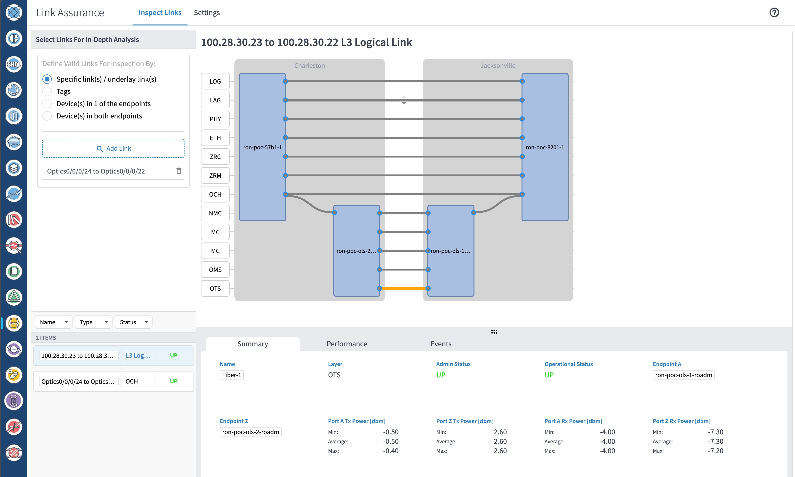
Verify the router optics controller state using the Link Assurance tool in Crosswork Hierarchical Controller. See Step 4 in Provision Routed Optical Networking ML Service Using Crosswork Hierarchical Controller.
-
-
-
Add SR-PCE, NSO, and Routers to Crosswork Network Controller
Perform these steps to add SR-PCE providers, NSO providers, and routers to Crosswork Network Controller.
Note |
When you add or import devices, or create providers, you need to specify the credential profile. |
-
Log in to the Crosswork user interface.
-
To create a credential profile, choose Device Management > Credential Profiles from the main menu. See Manage Credential Profiles.
-
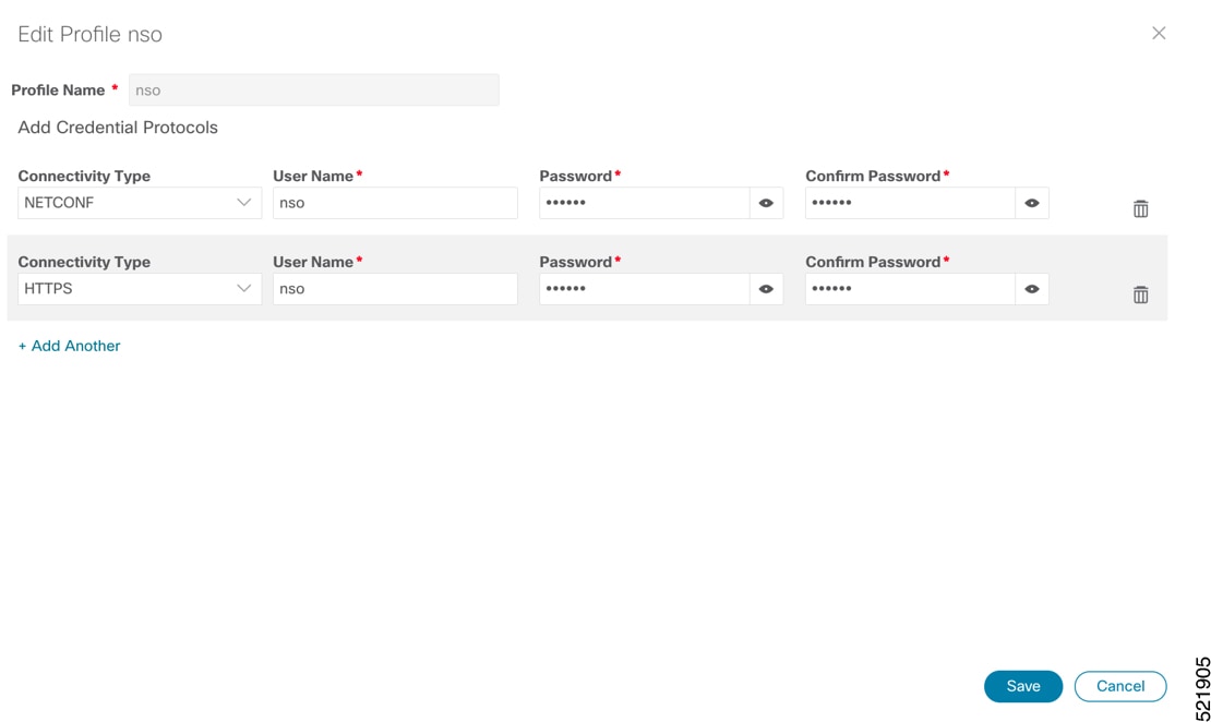
For the NSO credential profile, the connectivity type must be set to NETCONF and HTTPS. Optionally, HTTP can also be defined if HTTPS is not used in NSO.
-
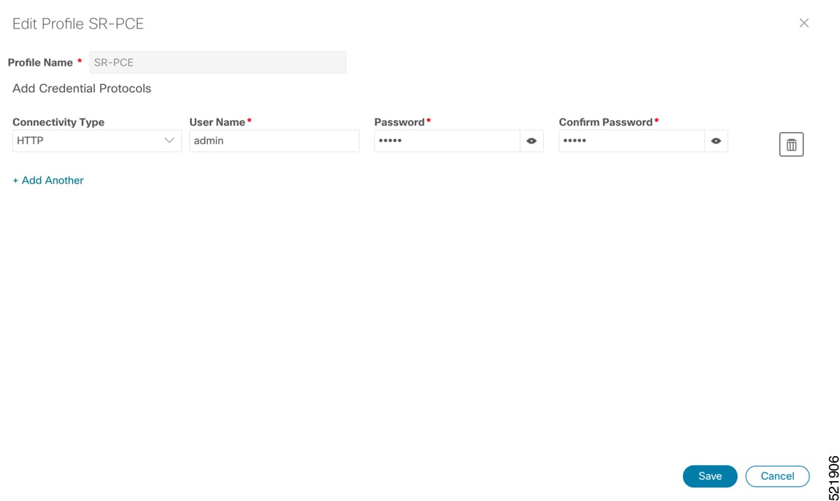
The SR-PCE credential profile requires HTTP credentials to communicate with the SR-PCE Northbound API.
-
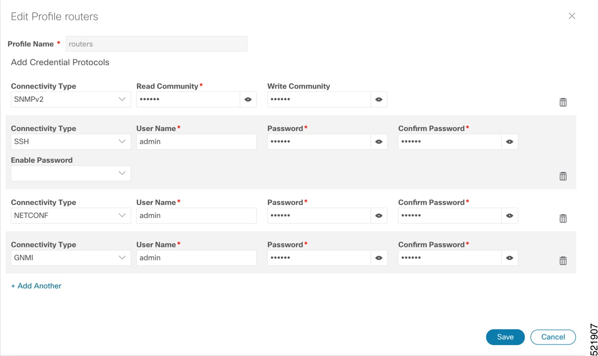
The router credential profile requires at a minimum, the SNMPv2 or SNMPv3 and SSH connectivity types. NETCONF is optional. GNMi is used when utilizing GNMi to configure streaming telemetry sensors on the node.
-
-
Add the providers. See About Adding Providers.
-
To add the SR-PCE or NSO provider, choose Administration > Manage Provider Access from the main menu. See Manage Providers.
-
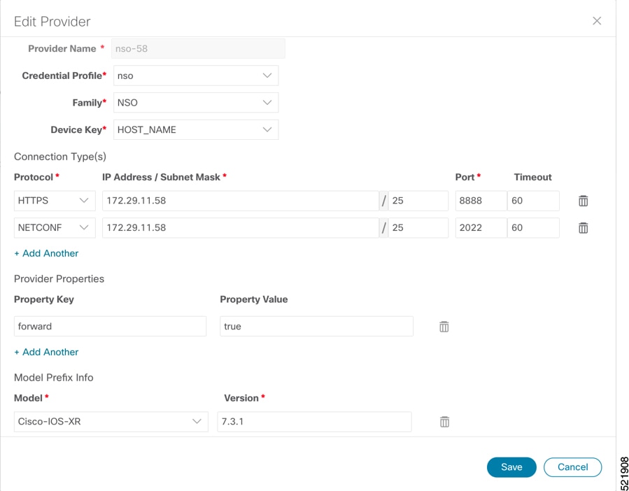
Add the NSO provider. See Add Cisco NSO Providers.
Select the credential profile created for NSO. Select the family as NSO. The Device Key may be set to either the HOST_NAME or INVENTORY_ID depending on the specific deployment.
The following image demonstrates the connectivity to NSO’s RESTCONF API over SSL using port 8888 and NETCONF using the default port of 2022. Since the Routed Optical Networking NSO CFP utilizes the XR CLI NED, the Cisco-IOS-XR model is not applicable and may be set to any version.
-
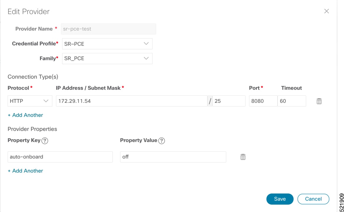
Add the SR-PCE provider. See Add Cisco SR-PCE Providers.
Select the credential profile created for SR-PCE. Select the family type as SR_PCE. The connectivity type for SR-PCE must be the HTTP. In the following image, the default API port of 8080 is specified. When the Property Key, "auto-onboard" is set to a Property value, "off", Crosswork Network Controller does not automatically add nodes that are discovered via the SR-PCE IGP topology to the device inventory. Devices must be added through the Crosswork Network Controller UI or inventory API.
-
-
Validate communications with one or more providers. Check on the provider's reachability using the steps in Get Provider Details.
-
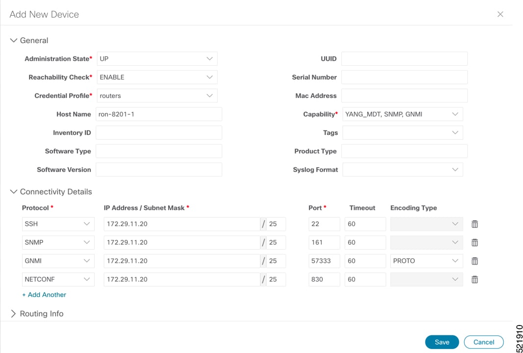
Onboard devices. See Add Devices Through the UI.
-
The Administration State, Reachability Check, and Credential Profile are mandatory elements. The Host Name must be used if the NSO provider device key is set to the Host Name value. If the NSO provider device key is set to Inventory ID that field must be populated. The Software Type, Software Version, UUID, Serial Number, MAC address, and Product Type are filled by device discovery. Optionally, tags can be applied to the device. The GNMI encoding type can be set to JSON or PROTO.
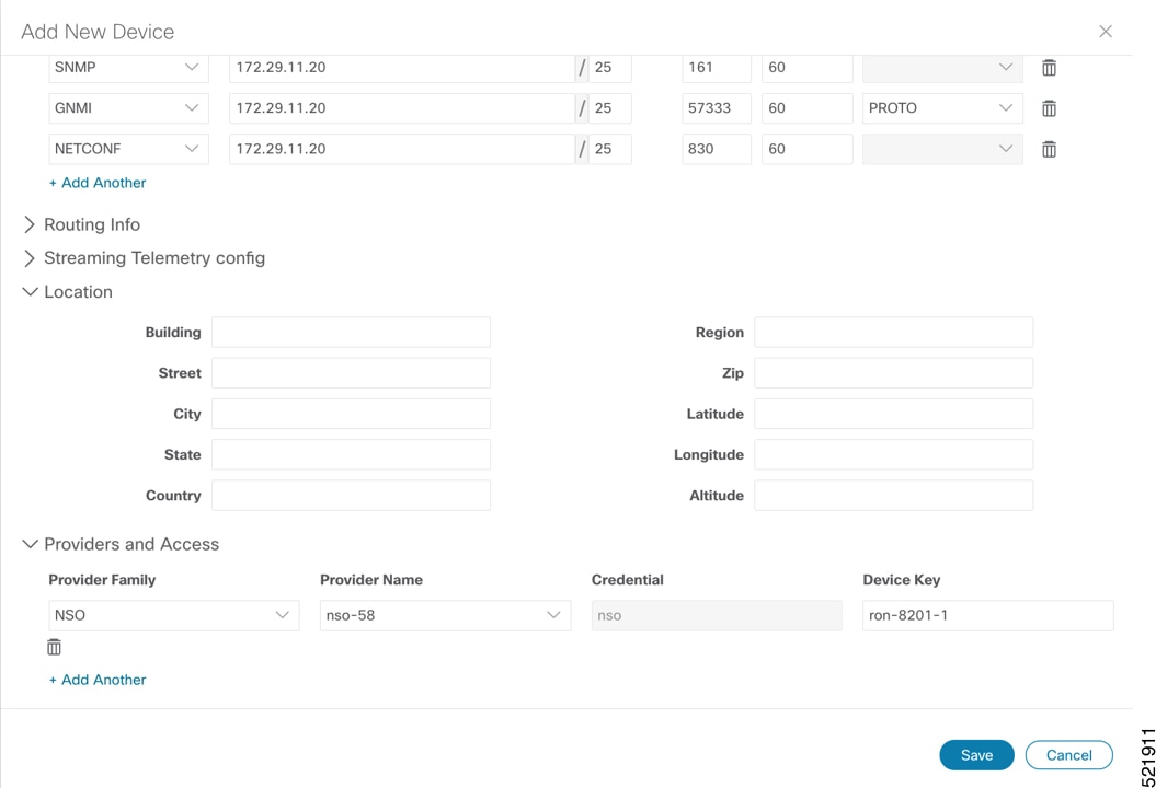
Optionally, location information can be entered. Latitude and Longitude information place the node at a specific location on a geographic map.
Add the previously configured NSO provider as a provider for the device.
-
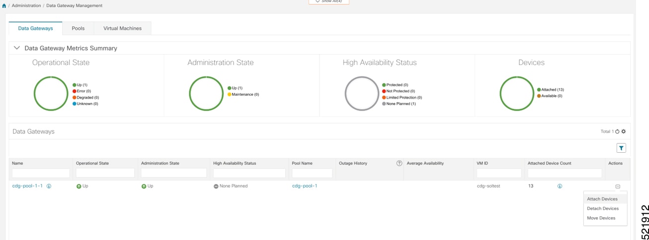
Attach the devices to an active Cisco Crosswork Data Gateway pool to manage them (device discovery).
Review the Data Gateways pane (see Overview of Cisco Crosswork Data Gateway). The operational state of the Cisco Crosswork Data Gateway pool to which you want to attach devices must be Up.
Follow the steps in Attach Devices to Cisco Crosswork Data Gateway.
-
Configure Adapters for Crosswork Hierarchical Controller
Prerequisite
When you work with Crosswork Hierarchical Controller adapters you are required to use credentials. These credentials are used for authentication when a device is assigned to an adapter. The same credentials may be shared by multiple adapters. The credentials are added under the Services > Device Manager > Credentials tab in the Crosswork Hierarchical Controller GUI. The adapters needed for the Routed Optical Networking solution are:
|
Adapter |
Credential Type |
|---|---|
|
Crosswork Network Controller |
HTTP (username/password) |
|
Crosswork Network Controller Crosswork Data Gateway |
HTTP (username/password) |
|
Cisco Optical Network Controller |
HTTP (username/password) |
|
IOS-XR |
SSH - User and password |
Note |
If Cisco Optical Network Controller and Crosswork Network Controller are on the same Crosswork cluster, they can use the same credential profile. |
To add the adapters, perform the following steps:
-
In the applications bar in Crosswork Hierarchical Controller, select Services > Device Manager > Adapters.
-
Click Add new adapter.
-
Enter the adapter details:
-
Adapter Type: Select an adapter type from the list of available adapter types currently installed in Crosswork Hierarchical Controller.
-
Adapter Name: Unique user defined name of this adapter type instance (there can be several instances of the same adapter type).
-
-
To configure the adapter, select the adapter in the Adapters pane. Configure the parameters as displayed in the following images.
-
Crosswork Network Controller Adapter:
Note
API version for Crosswork Network Controller must be V2.
Figure 1. Crosswork Network Controller Adapter Configuration - General Tab 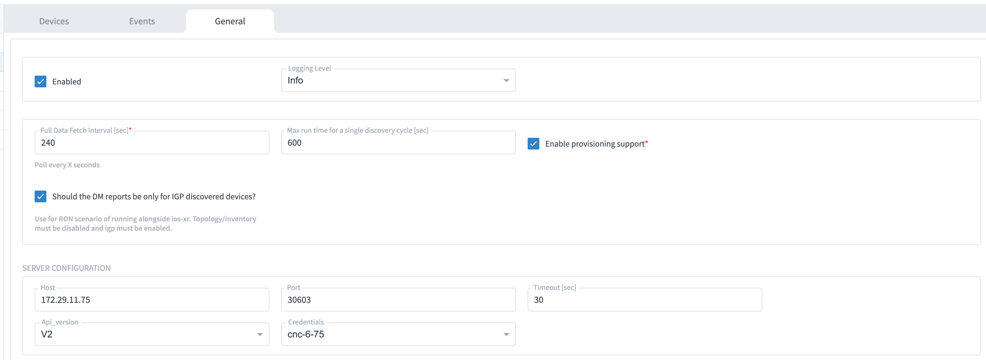
Note
The Full Data Fetch Interval must be set to 300s or higher in a production network.
The following parameters must be configured for Crosswork Network Controller notifications and collection.
Figure 2. Crosswork Network Controller Notifications 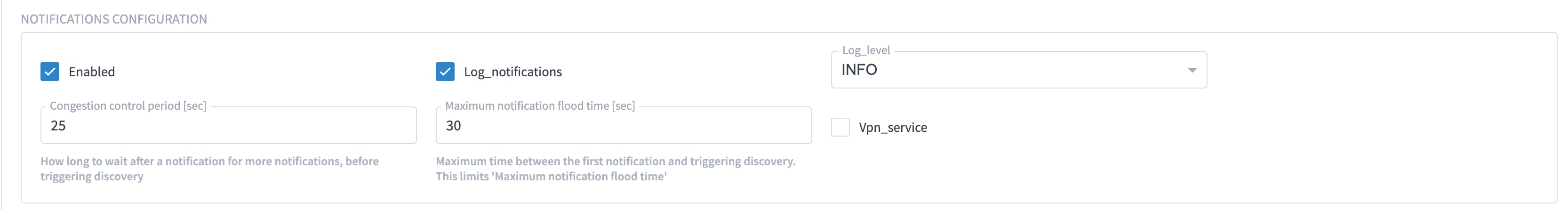
Figure 3. Crosswork Network Controller Collection and Provisioning 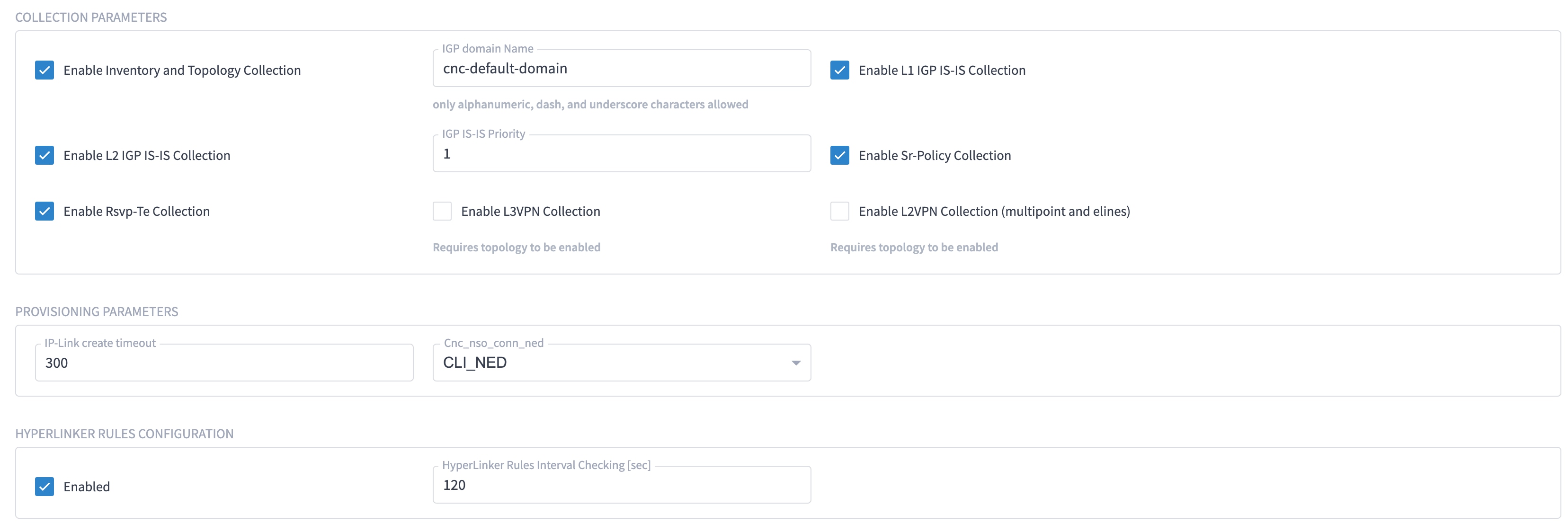
-
IOS-XR Adapter
Figure 4. IOS-XR Adapter - General Tab 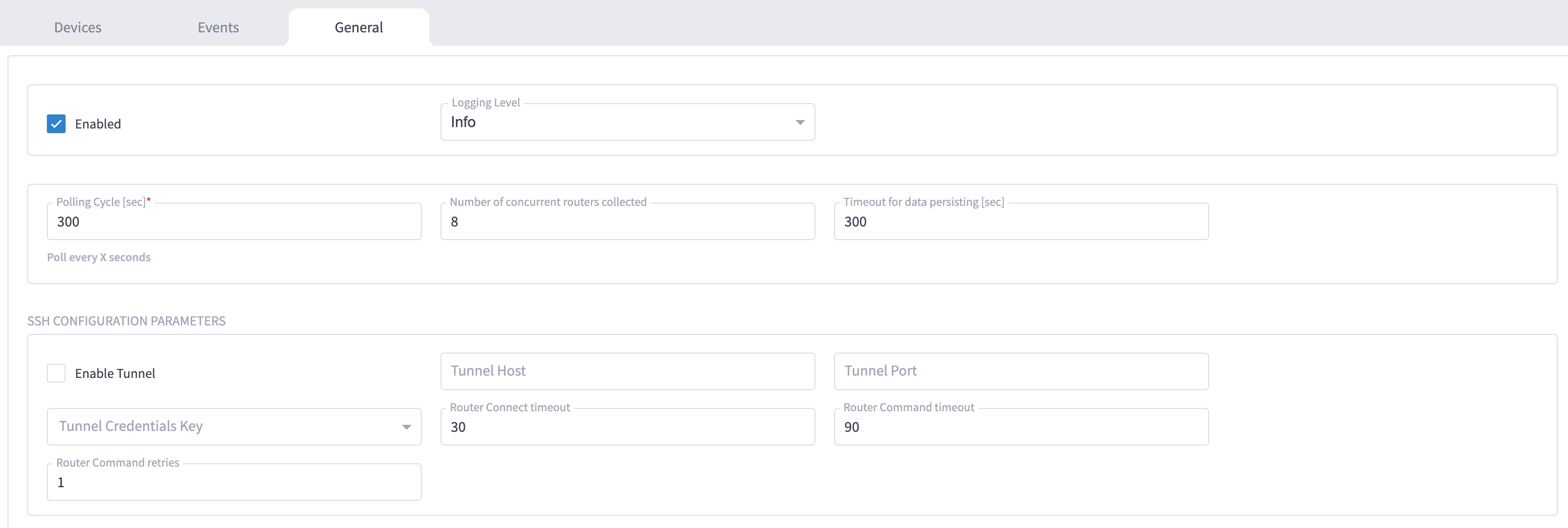
Note
The Polling Cycle should not be less than 300s in a production network. Concurrency can be increased. The Logging Level must be set to Info if everything is working correctly.
The following collection parameters must be configured. These parameters collect optical power values for the link assurance application.
Figure 5. IOS-XR Adapter - General Tab 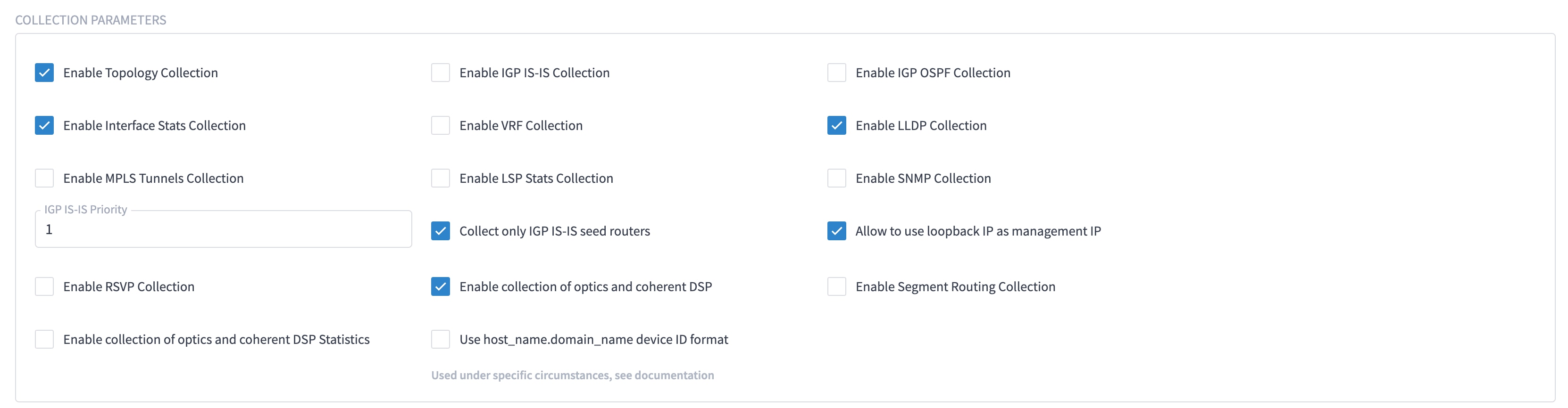
Note
Check the Enable collection of optics and coherent DSP Statistics parameter only when using Automation Starter Solution.
Figure 6. IOS-XR Adapter - General Tab 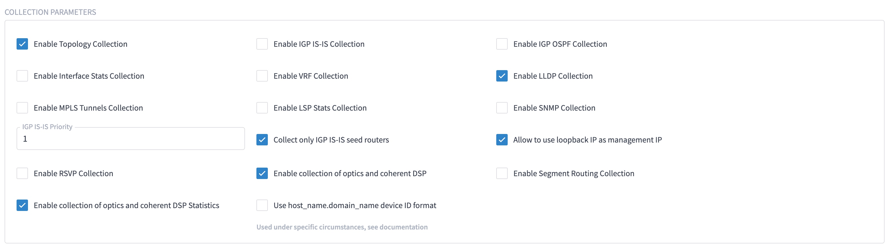
The status of the devices must be ok in the Devices tab after the addition and completion of a successful collection cycle.
Figure 7. IOS-XR Adapter - Devices Tab 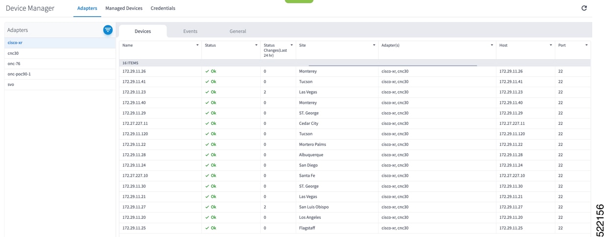
To add routers to Crosswork Hierarchical Controller, click the Managed Devices tab and then + Add Device.
Figure 8. IOS-XR Adapter -Add New Device - General Tab 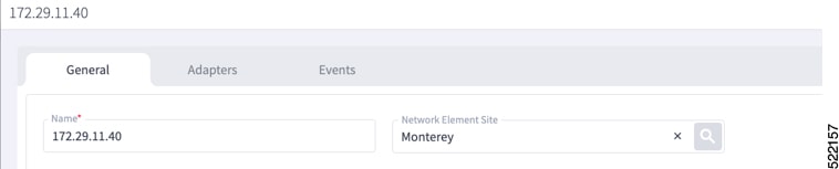
It is recommended to use the hostname+hco (ron-8201-1-hco) or the device IP address. The device must be assigned a site for it to be displayed in the Explorer UI.
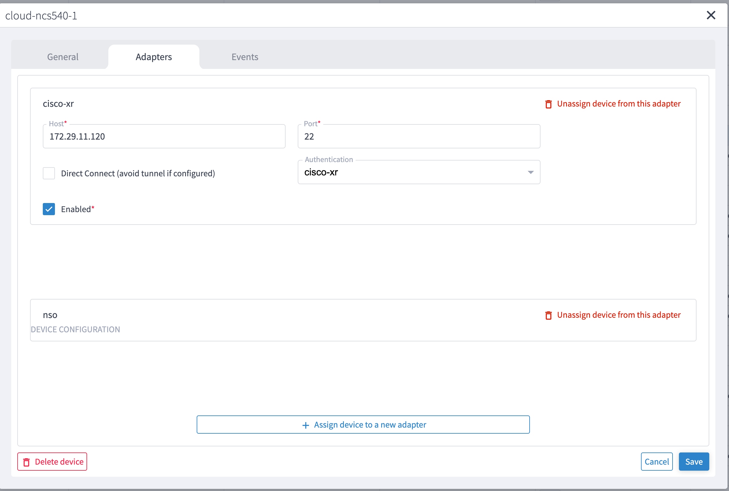
Assign both the IOS-XR and Crosswork Network Controller adapter type to the device. Do not enable discovery for the Crosswork Network Controller adapter.
Figure 9. IOS-XR Adapter -Add New Device - Adapters Tab 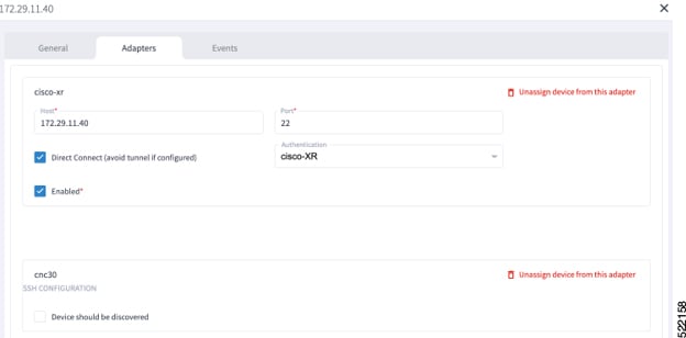
-
Cisco Optical Network Controller Adapter
Figure 10. Cisco Optical Network Controller Adapter - General Tab The Polling cycle must be set to 300s or higher in a production network. Polling retrieves TAPI SIPs, topology, and connectivity services.
The URL in the following figure is for the Cisco Optical Network Controller 3.1.
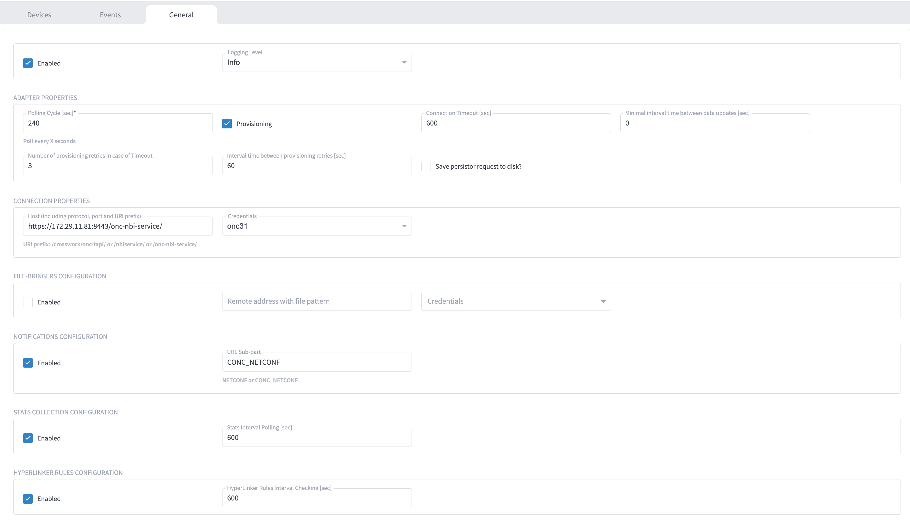
The optical nodes are discovered automatically from Cisco Optical Network Controller. Nodes must be assigned a site for it to be displayed in the Explorer UI.
Figure 11. Cisco Optical Network Controller Adapter - Devices Tab 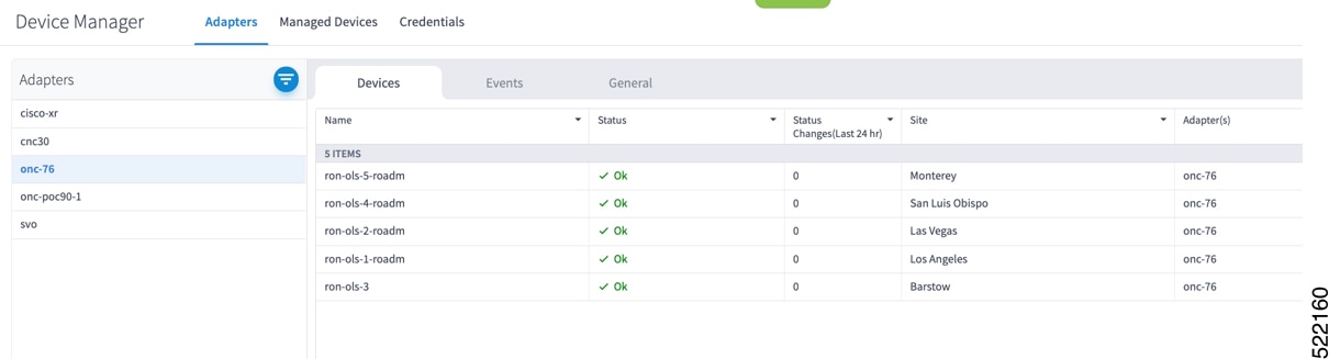
-
Crosswork Network Controller Crosswork Data Gateway Adapter
Crosswork Network Controller Crosswork Data Gateway adapter is used to collect telemetry data via gNMI to the router. In Crosswork Network Controller, the routers must be configured with the gNMI protocol with the encoding type set to “PROTO” and the GNMI capability enabled. In IOS XR, the routers must be configured for gRPC so that Crosswork Data Gateway can create gNMI telemetry subscriptions.
Figure 12. Crosswork Network Controller Crosswork Data Gateway Adapter 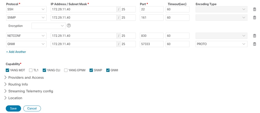
The Crosswork Data Gateway adapter is configured to connect to Crosswork Network Controller controlling Crosswork Data Gateway instance. It can be the same as the Crosswork Network Controller used for the topology or a different Crosswork Network Controller. The collection parameters describe the supported telemetry collection jobs. The statistics show up in the physical interface statistics and in the Link Assurance application.
Figure 13. Crosswork Network Controller Crosswork Data Gateway Adapter - General Tab 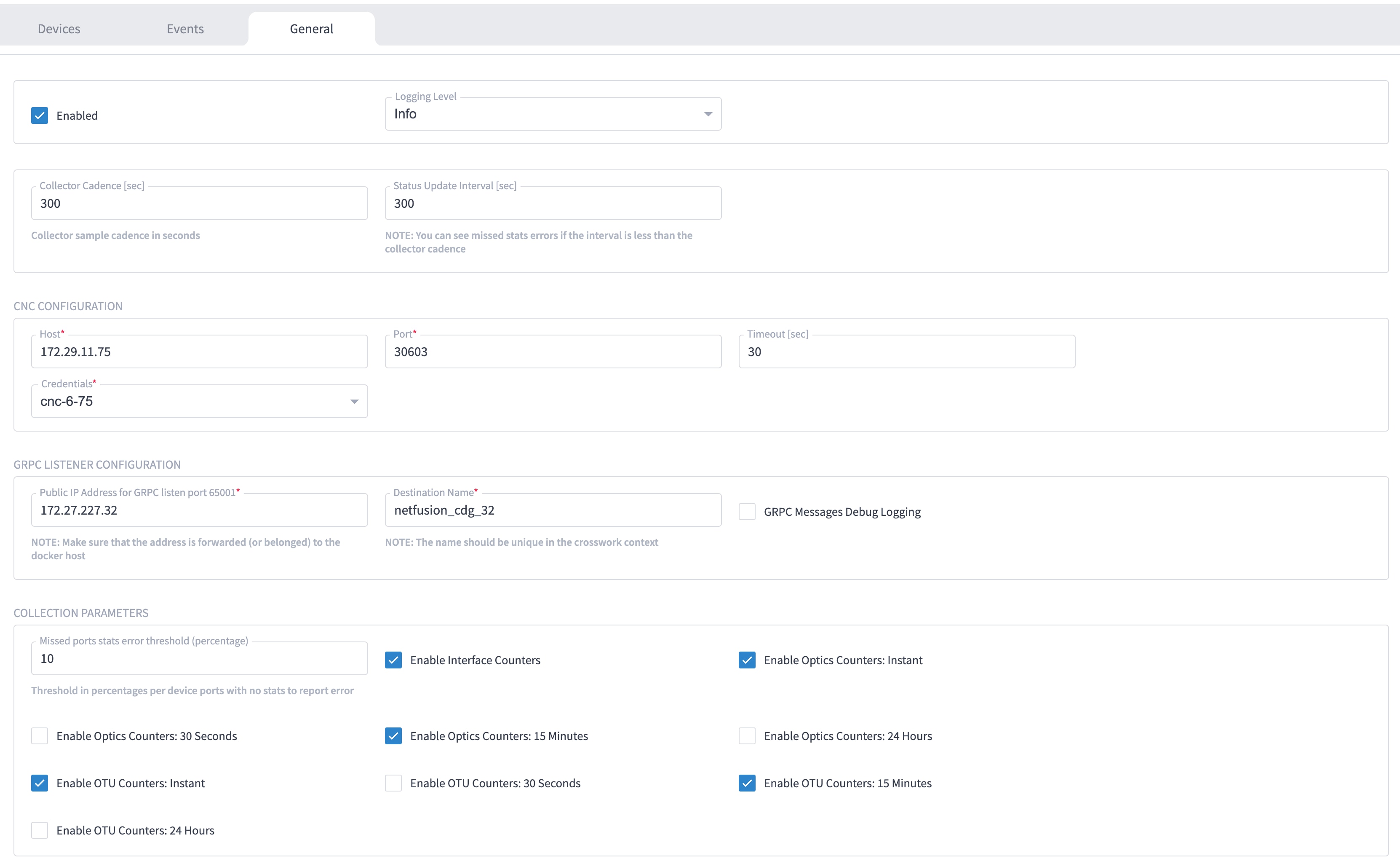
-
The device name in Cisco Crosswork Hierarchical Controller must match the device name in Crosswork Network Controller for successful deployment. If successful, you will see Cisco Crosswork Hierarchical Controller as a new destination in Crosswork Network Controller. This is setup by Cisco Crosswork Hierarchical Controller and user interaction is not required. As Crosswork Data Gateway is enabled on devices, new collection jobs are populated. A single collection job is available for each router collecting multiple KPIs.
Figure 14. Crosswork Network Controller Crosswork Data Gateway Adapter - Data Destinations 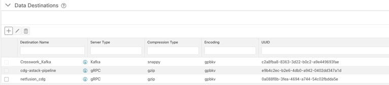
Figure 15. Crosswork Network Controller Crosswork Data Gateway Adapter - Collection Jobs 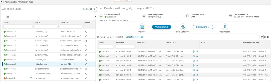
-
NSO Adapter In Hierarchical Controller
In Hierarchical Controller 8.0 there is an embedded NSO installed when Hierarchical Controller 8.0 is installed. The NSO adapter can use the internal NSO or point to an external NSO instance. Provisioning using the NSO adapter requires adding the NSO adapter to the devices you want to provision.
Use the NSO adapter when you use the Automation Starter Solution.
Note
-
If using the internal NSO, the Routed Optical Networking 3.0 Core Function Pack must be installed on the NSO instance.
-
If using the internal NSO, devices must be added to that NSO, adding them to Hierarchical Controller does not automatically onboard them into the internal NSO.
Figure 16. NSO Adapter - General Tab 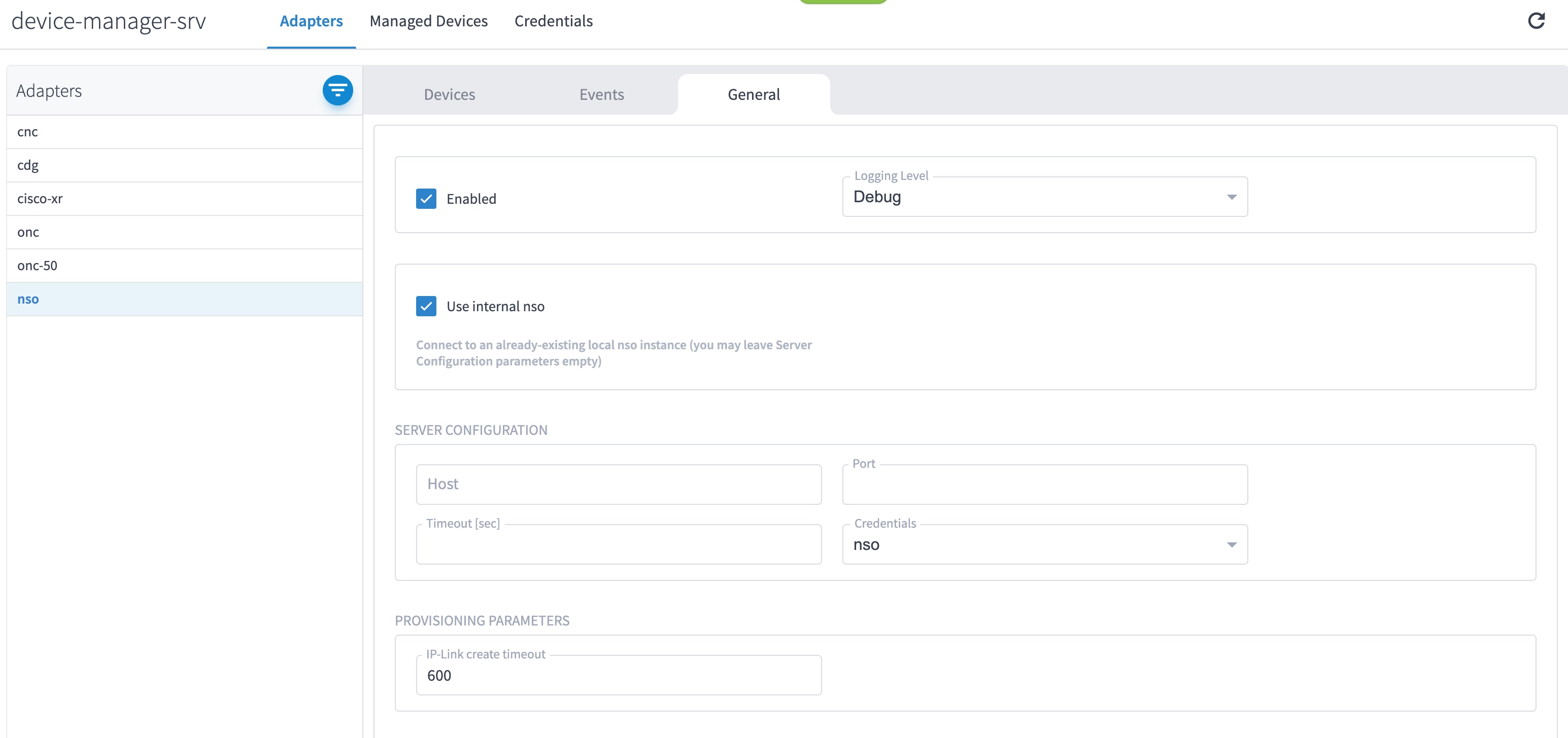
Start configuration with NSO and XR adapters.
-
-
Configure SSO in Crosswork Hierarchical Controller
This section describes how to configure SSO in Crosswork Hierarchical Controller with Crosswork Network Controller as Identity Provider. You can use the same SSO configuration to set up SSO for Cisco Optical Network Controller Release 3.1.
-
Configure Crosswork Hierarchical Controller
-
Click
Enter the necessary information:
-
Login URL: https://<CNC_IP>:<port>/crosswork/sso/idp/profile/SAML2/Redirect/SSO
-
Entity ID: https://<CNC_IP>/idp
-
Certificate: Copy from Crosswork Network Controller metadata frm https://<CNC_IP>:<port>crosswork/sso/idp/metadata
-
Use Groups Attribute Name
authenticationMethod
Figure 17. Crosswork Hierarchical Controller Provider Configuration Sample 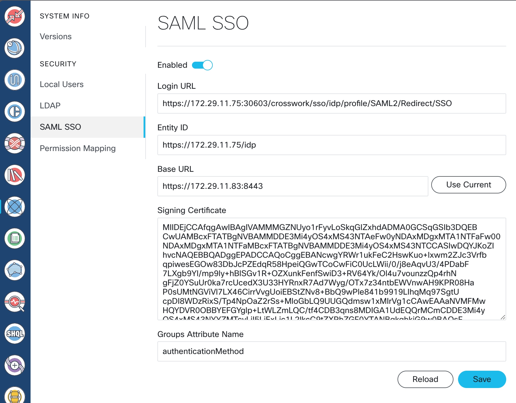
-
-
Click
Figure 18. Crosswork Hierarchical Controller Permission Mapping Sample 
-
Add a Match condition for SAML Group of QueryDatabaseAuthenticationHandler with a permission of
permission/adminFigure 19. Crosswork Hierarchical Controller Permission Mapping Sample 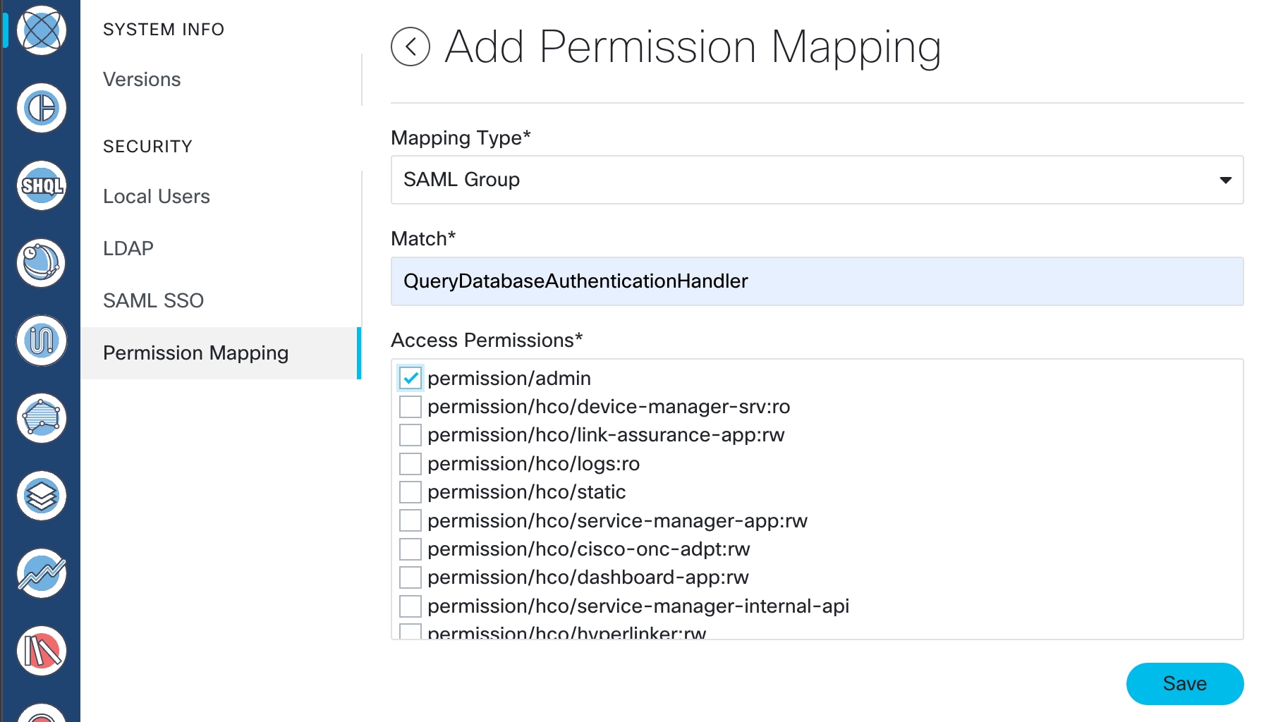
-
-
Copy Crosswork Hierarchical Controller SAML metadata to a file, metadata is located at https://<HCO_IP>:<port>/sso/metadata. The following is a sample.
<EntityDescriptor entityID="https://172.29.11.83:8443" xmlns="urn:oasis:names:tc:SAML:2.0:metadata" xmlns:assertion="urn:oasis:names:tc:SAML:2.0:assertion" xmlns:ds="http://www.w3.org/2000/09/xmldsig#"> <SPSSODescriptor AuthnRequestsSigned="false" WantAssertionsSigned="false" protocolSupportEnumeration="urn:oasis:names:tc:SAML:2.0:protocol"> <NameIDFormat>urn:oasis:names:tc:SAML:1.1:nameid-format:emailAddress</NameIDFormat> <SingleLogoutService Binding="urn:oasis:names:tc:SAML:2.0:bindings:HTTP-Redirect" Location="https://172.29.11.83:8443/sso/logout"> </SingleLogoutService> <AssertionConsumerService index="0" Binding="urn:oasis:names:tc:SAML:2.0:bindings:HTTP-POST" Location="https://172.29.11.83:8443/sso/acs"> </AssertionConsumerService> </SPSSODescriptor> </EntityDescriptor> -
Configure Crosswork Network Controller
-
Login to Crosswork Network Controller, click
Figure 20. Crosswork Network Controller AAA 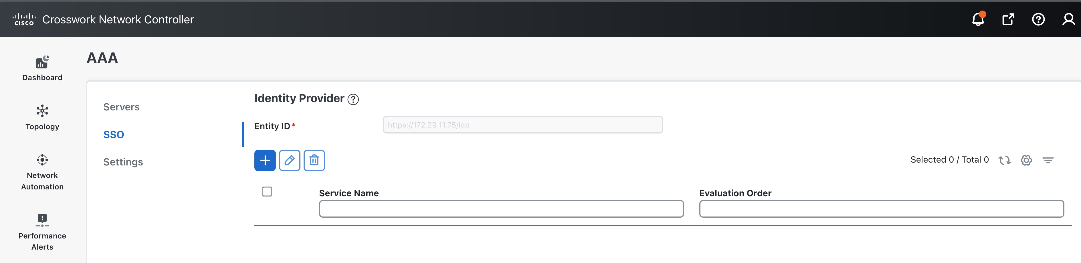
-
Click +
-
Add a name
-
Add a unique evaluation order number
-
Upload HCO’s Metadata file in XML format
Figure 21. Crosswork Network Controller Add new Service Provider 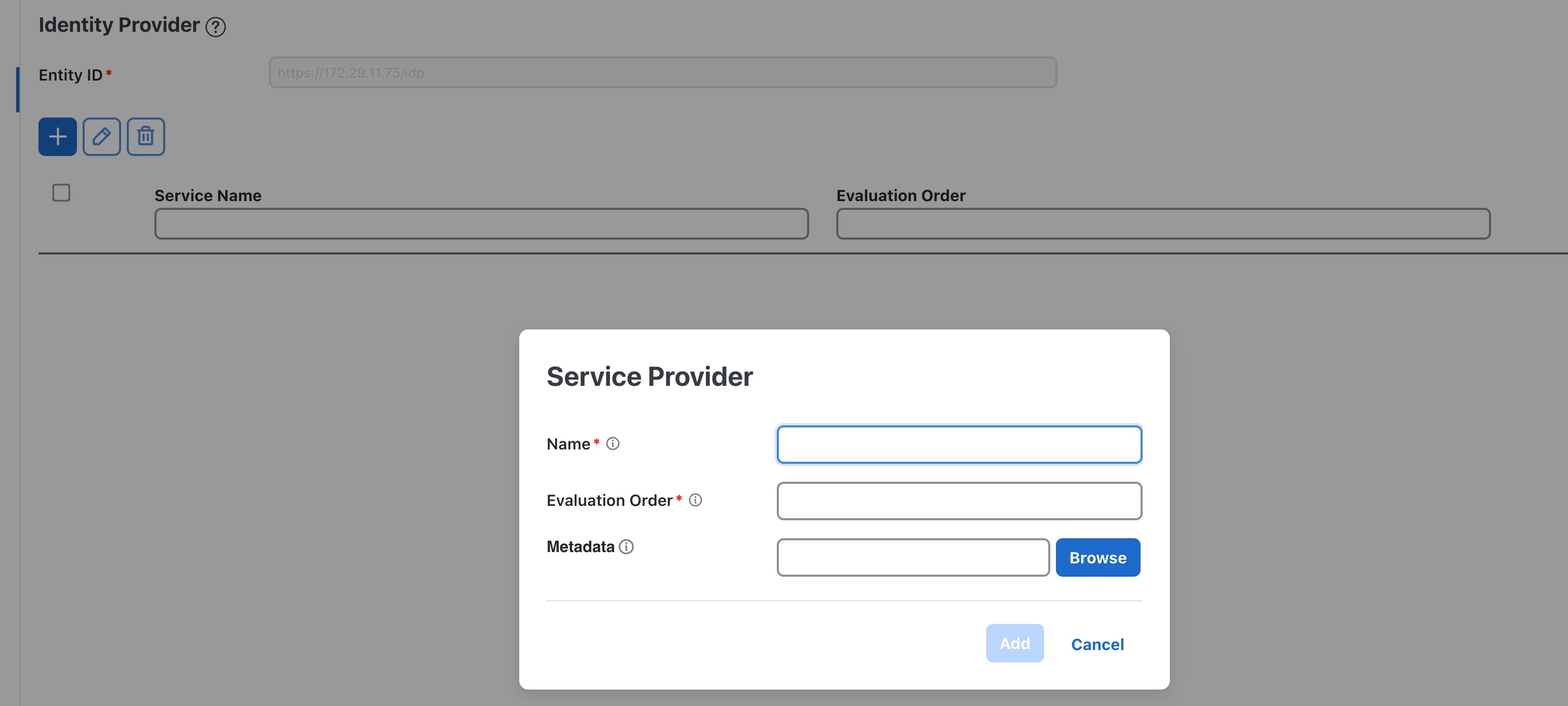
-
-
Click Save
Figure 22. Crosswork Network Controller AAA
-
-
Login to
Figure 23. Crosswork Network Controller AAA 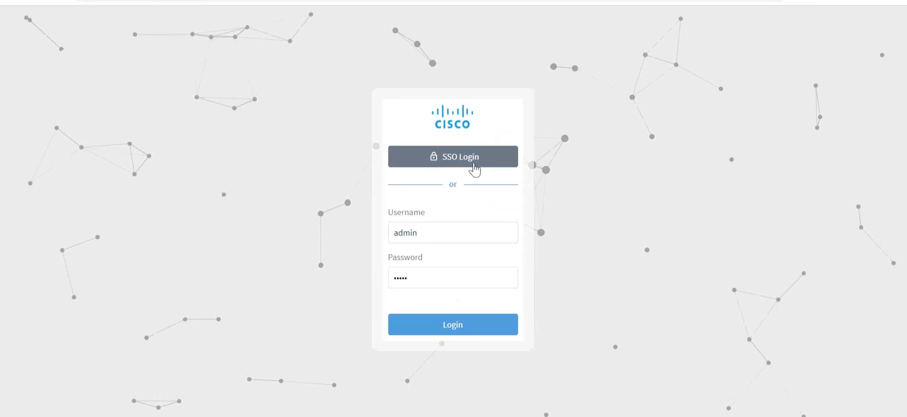
Troubleshooting Cisco Crosswork Hierarchical Controller SSO
-
Use the sedo logs security audit in the Crosswork Hierarchical Controller to get the logs.
-
Ensure time is syncronised between Cisco Crosswork Hierarchical Controller and Cisco Crosswork Network Controller
-
If there is an error related to
QueryDatabaseAuthenticationHandleradd the SAML group mapping in Crosswork Hierarchical Controller configuration, map to group Admin
Examples of Cross Launch
SSO is supported across Hierarchical Controller 8.0, Crosswork Network Controller 6.0, and Cisco Optical Network Controller/Cisco Optical Site Manager.
-
Cross Launch from IGP Link SRC/DST Router in Hierarchical Controller to Crosswork Network Controller
-
Click on
-
Hover over either Source Device or Destination Device, click the ellipsis and click IGP device at Crosswork Network Controller
Figure 24. Network Inventory 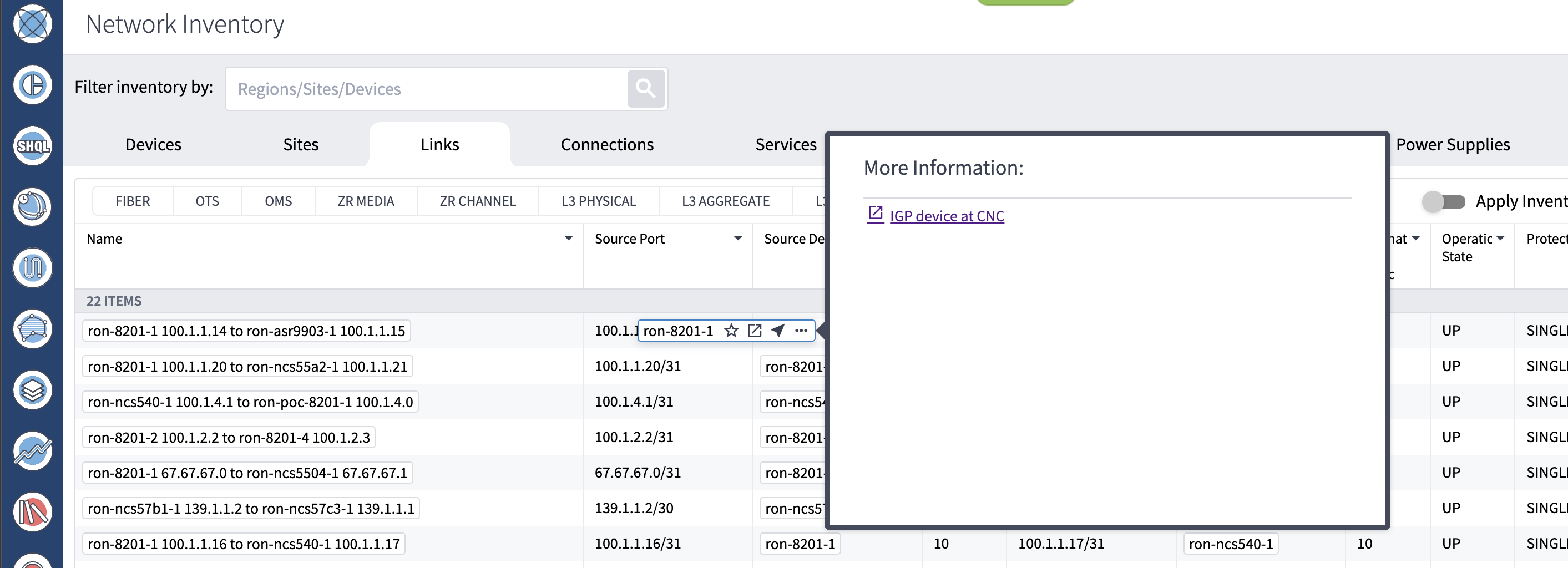
This operation launches the router traffic engineering information in Crosswork Network Controller.
Figure 25. Traffic Engineering 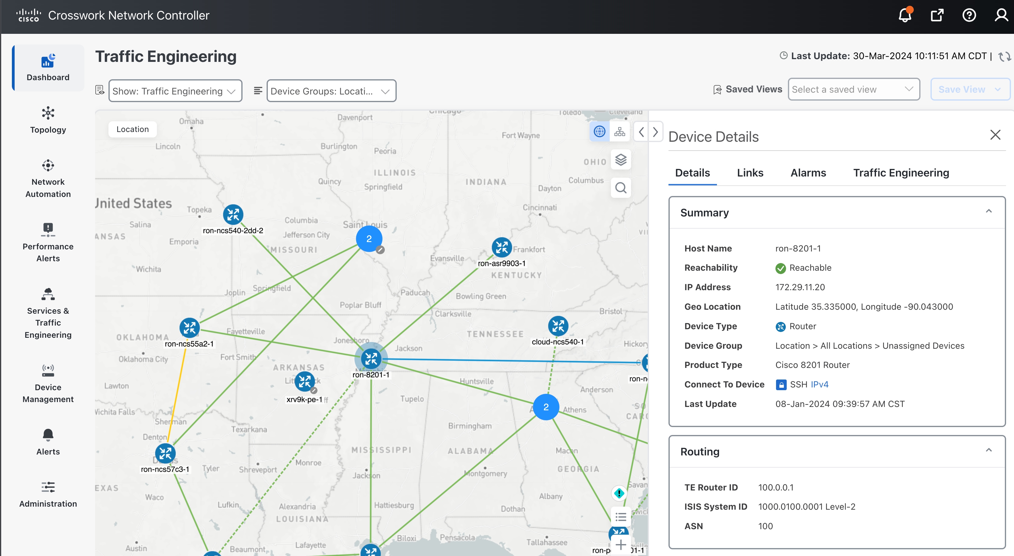
-
-
Hierarchical Controller SR Policy to Crosswork Network Controller
-
Click on
-
Hover over policy and click on ellipses to open cross launch.
Figure 26. Network Inventory 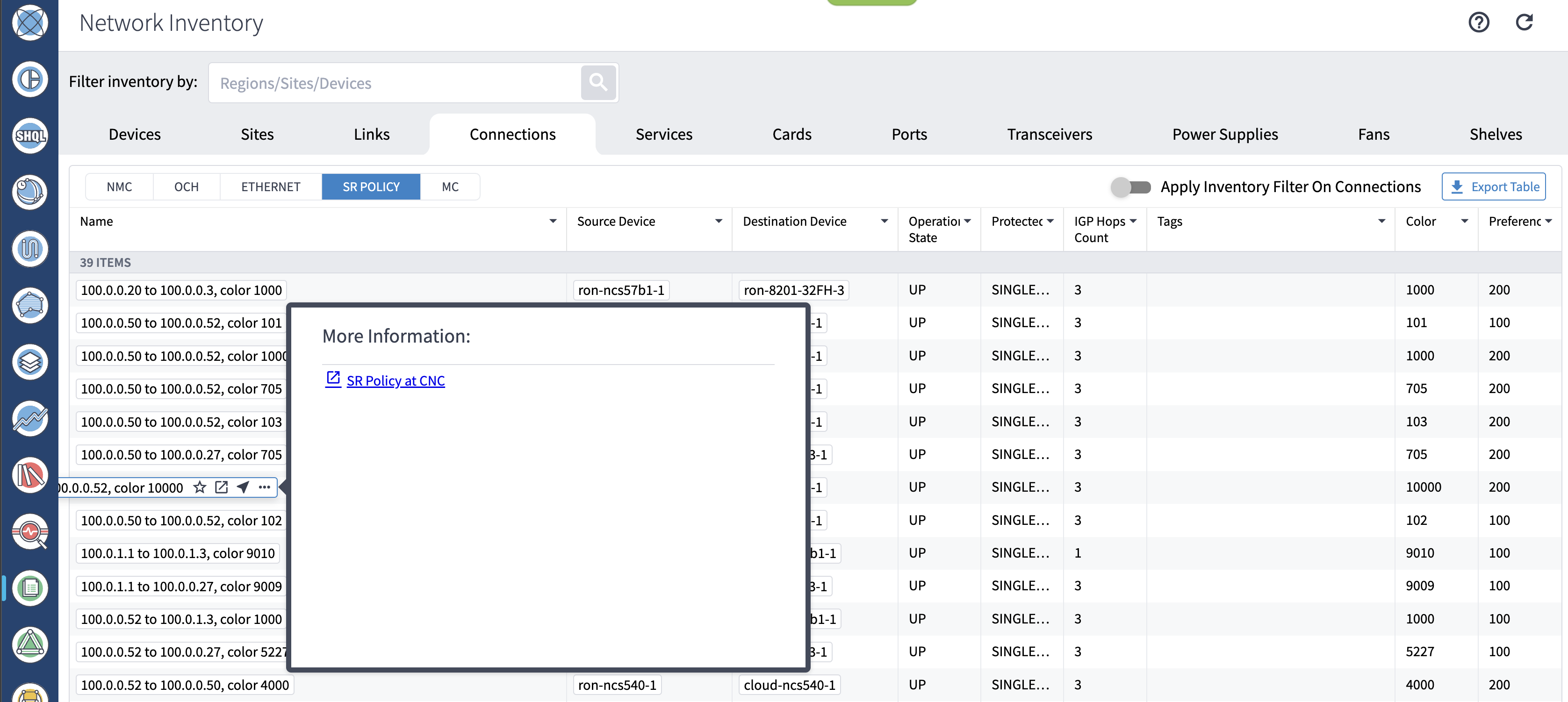
This operation launches detailed policy information in Crosswork Network Controller.
Figure 27. Traffic Engineering 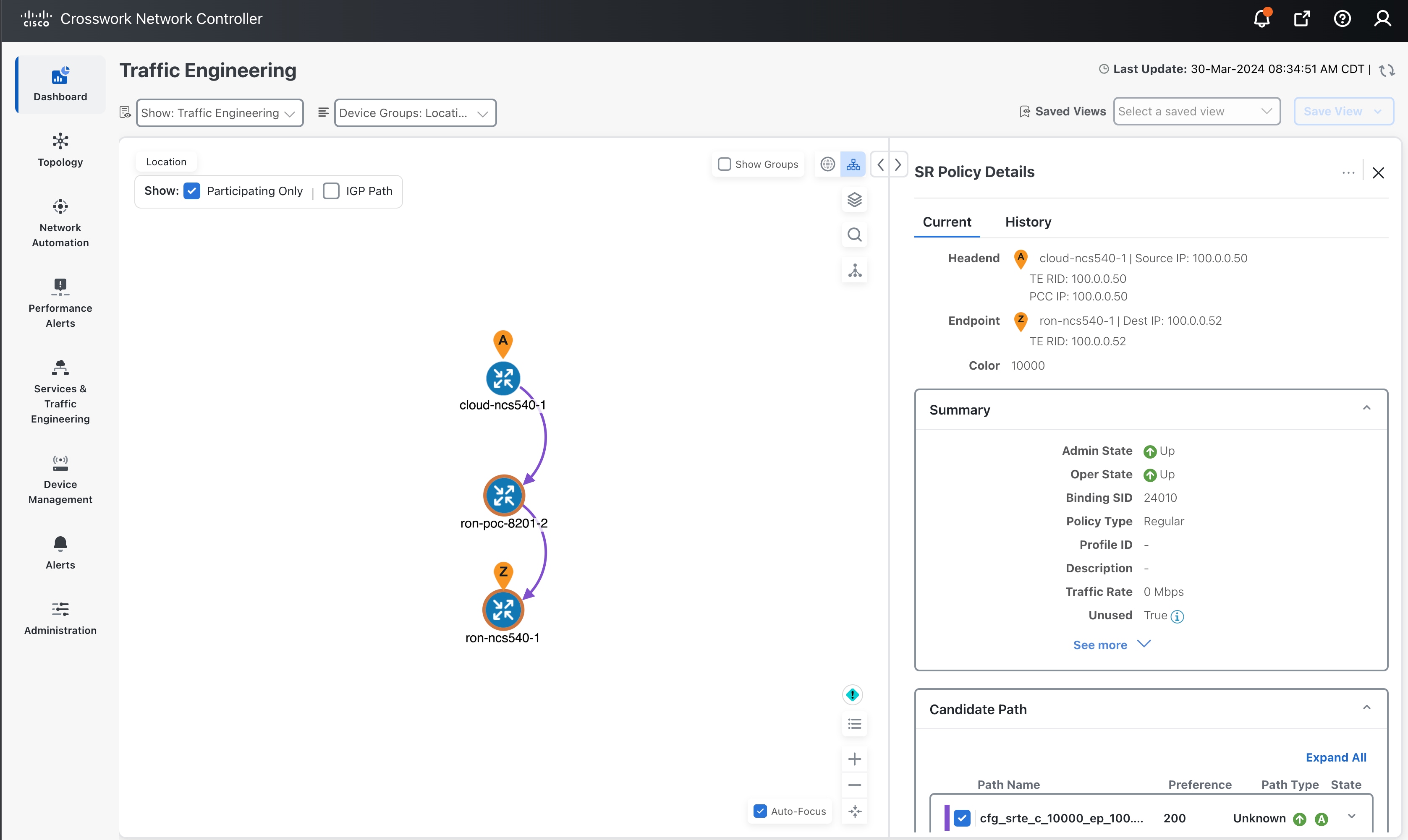
-
-
Hierarchical Controller Optical Node to Cisco Optical Site Manager
-
Click on
-
Hover over a device, click ellipsis and click Optical Node at COSM.
Figure 28. Network Inventory 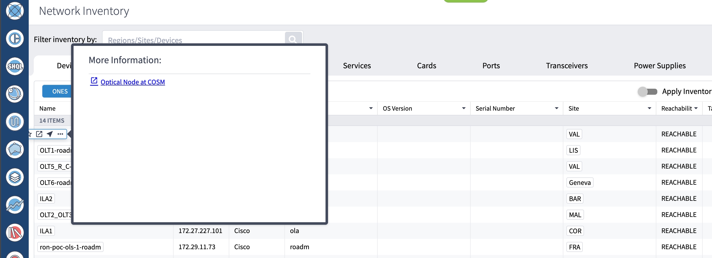
-
-
Hierarchical Controller Optical Port to Cisco Optical Site Manager
-
Click on
-
Hover over a port, click ellipsis and click Optical Port at COSM.
Figure 29. Network Inventory 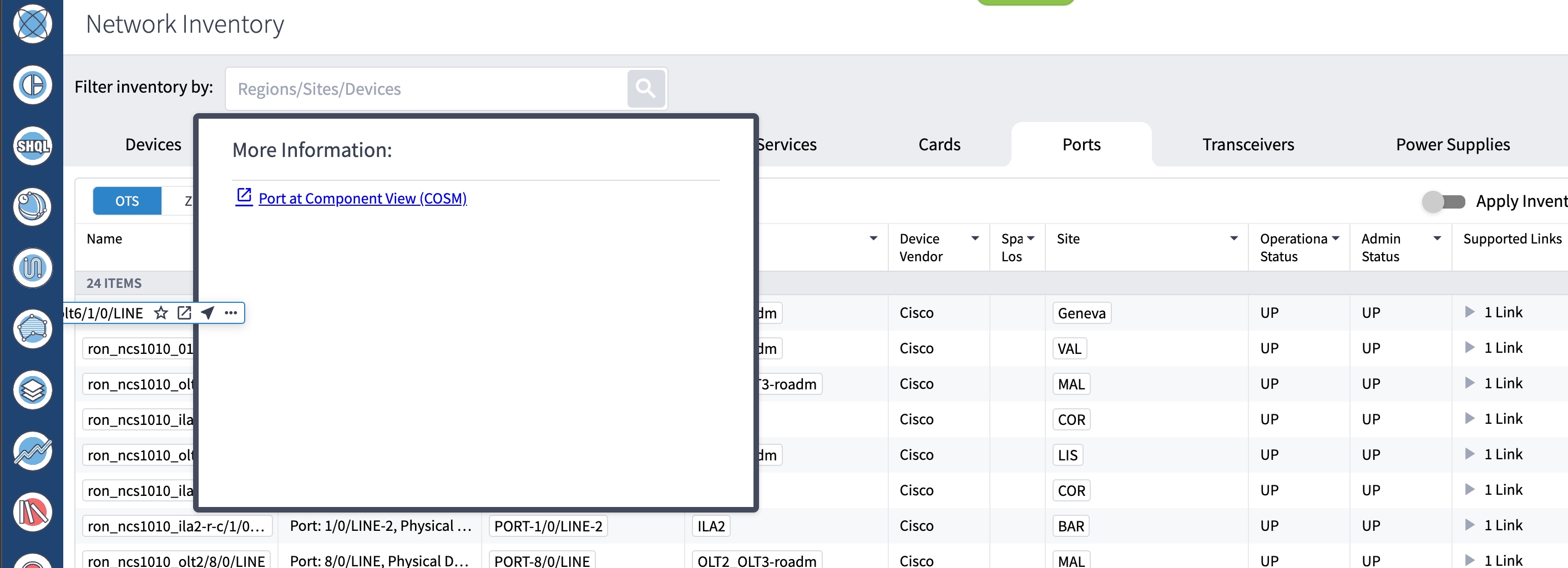
-
-
Hierarchical Controller Link Assurance Node to Cisco Optical Site Manager or SVO
-
Click
-
Hover over a node, click ellipsis and click Optical Node at COSM.
Figure 30. Link Assurance 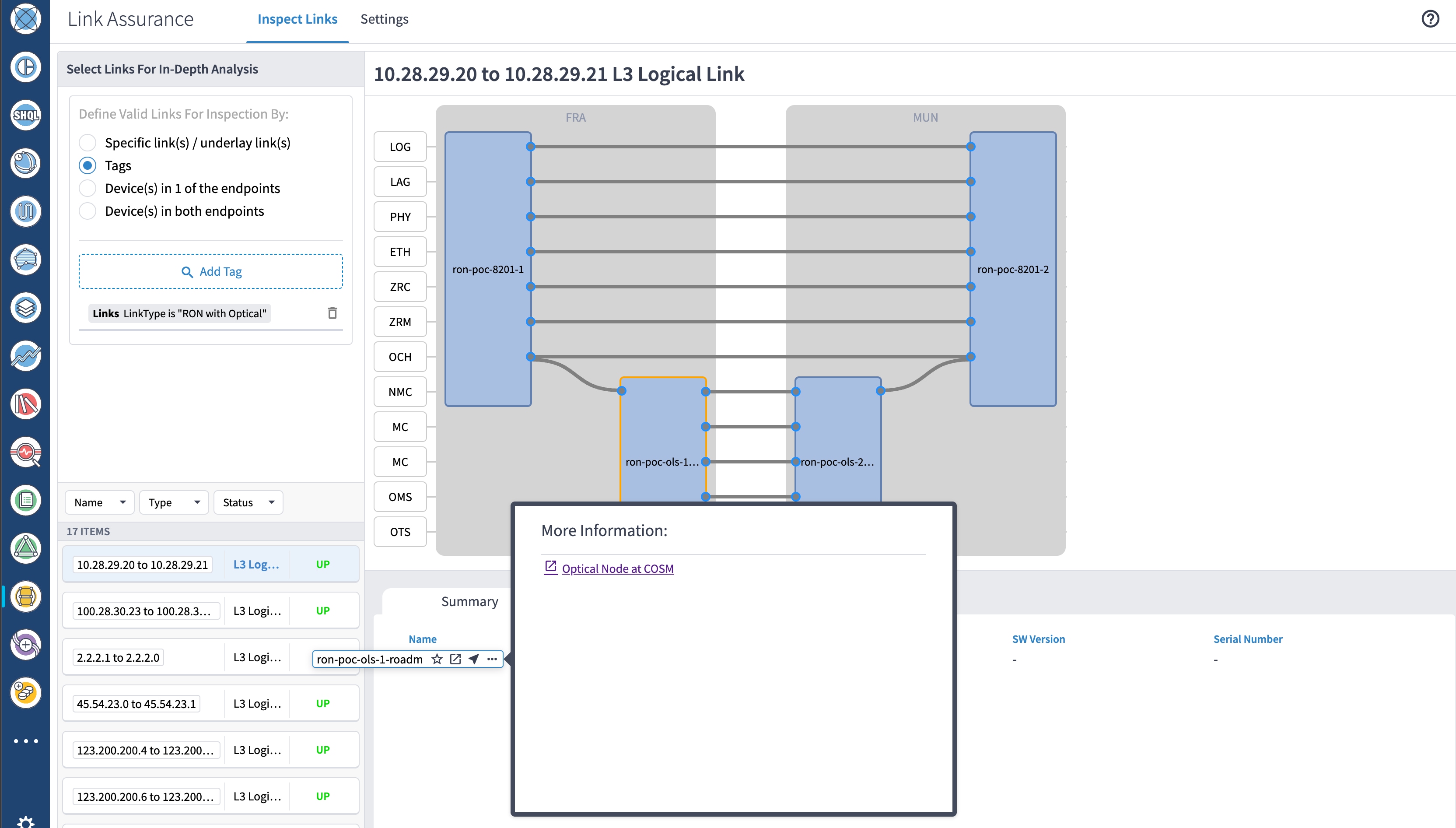
This operation launches the node functional view in Cisco Optical Site Manager (for NCS 1000 series devices) or SVO (for NCS 2000 series devices).
-
-
Hierarchical Controller Link Assurance Port to Cisco Optical Site Manager
-
Click
-
Hover over a port, click ellipsis and click Optical Port at COSM.
Figure 31. Link Assurance 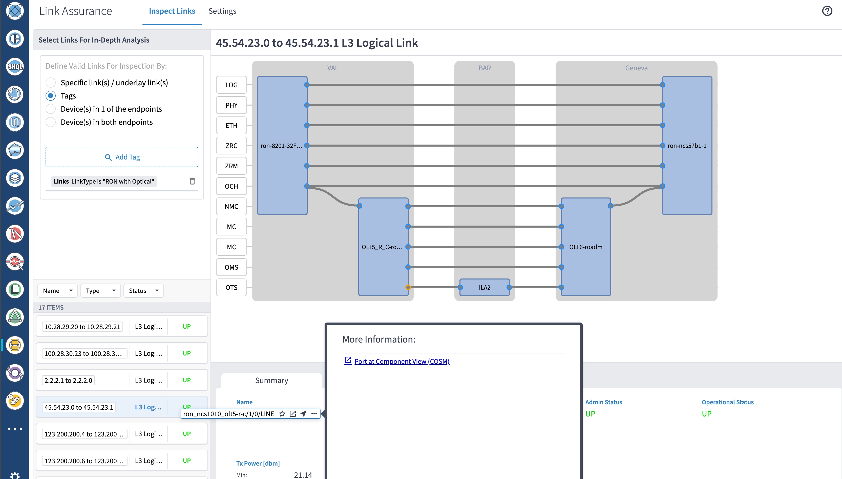
-
Provision ML Service Using NSO Routed Optical Networking CFP
Perform the following steps to provision the Routed Optical Networking ML service using the NSO Web UI.
-
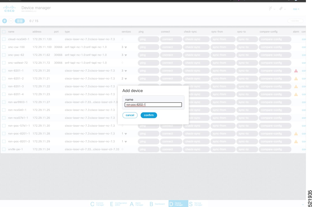
To add a new device, perform these steps:
-
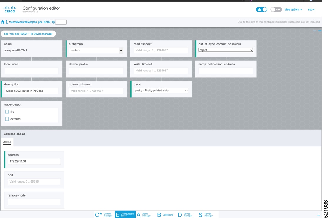
In the Device manager, click the + to add a new device. Specify a name for the new device. Click Confirm.
-
After creating the new device, click the device name to fill required and optional parameters. In this screen, the required parameters are the authgroup and IP address of the device.
-
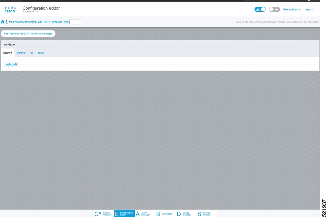
Scroll down in the device configuration screen. Click the “device-type” to bring up the device type selection screen. The device-type that is supported in the Routed Optical Networking ML FP is IOS-XR CLI NED.
-
Click the blue NETCONF text to select the proper NED. The Routed Optical Networking ML FP requires the use of the cisco-iosxr-nc-7.3 NED.

-
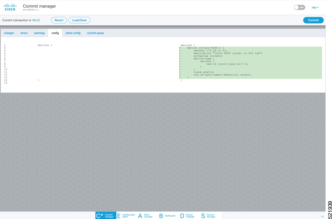
Click the Commit manager to view the NSO CLI configuration being applied. Click Commit to save the device configuration to NSO.
Note
Next we add the multilayer end-to-end service to configure and provision both the optical line system and routers. We recommend you to click check-sync in the Device manager to ensure that the device configuration is properly in sync with NSO before provisioning. If the device is out of sync, initial provisioning fails.
-
-
To create Routed Optical Networking ML service, perform these steps:
-
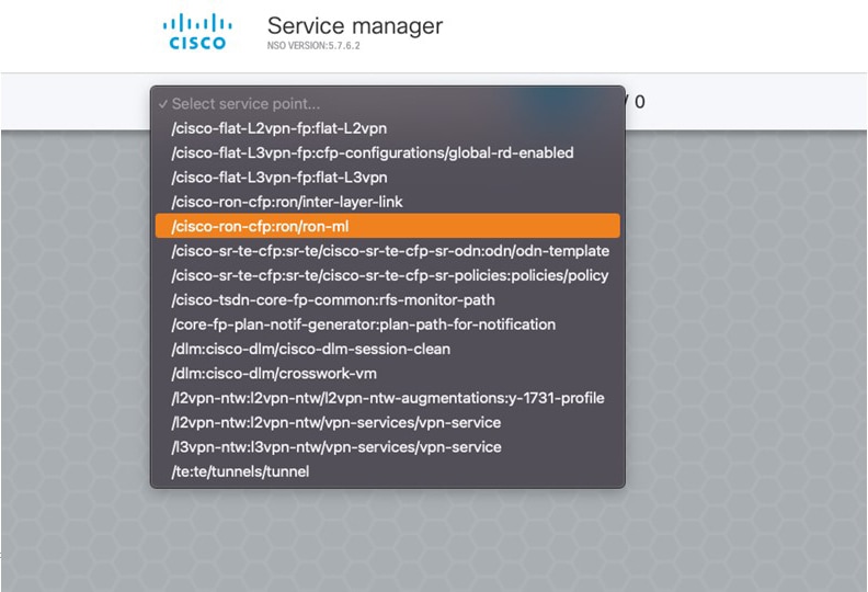
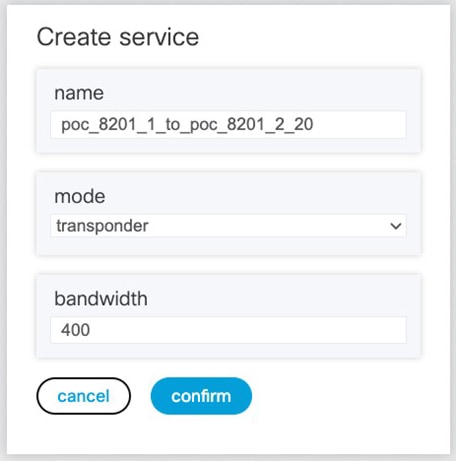
In the Service manager, select the Routed Optical Networking ML service point from the drop-down list. When we create the new Routed Optical Networking ML service, the required components are the service name, mode of the service (transponder or muxponder), and the bandwidth. The bandwidth corresponds to the line rate of the ZR/ZR+ optics. Click Confirm.
-
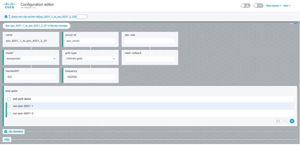
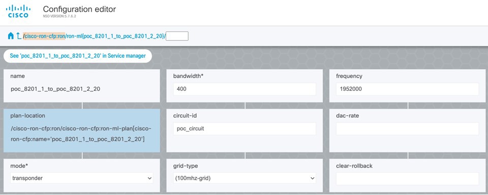
In the Configuration editor, click the newly created service name for editing the additional parameters that are required for the service. In this example, we set the circuit-id name in the global parameters. The frequency is set by the optical controller based on the specified optical add/drop port. The dac-rate is set to the default value.
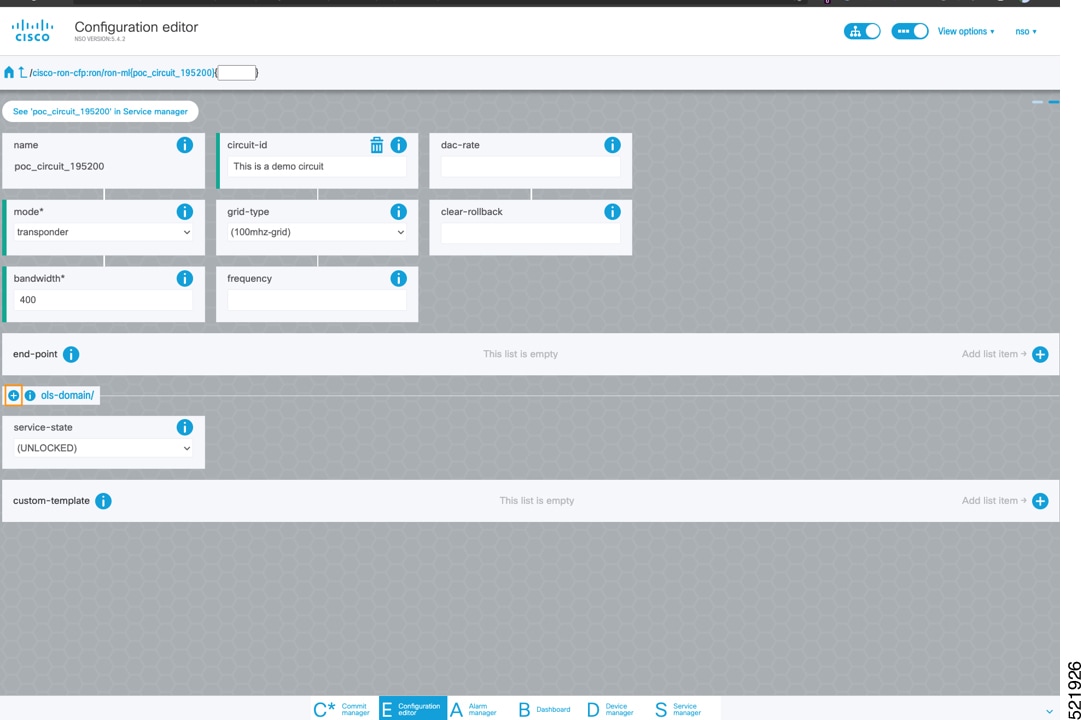
Note
-
User configuration global options are frequency and dac-rate
-
Dac-rate controls the TX shaping parameters: 1x1.25 = enabled, 1x1 = disabled. Leaving it blank uses system default of enabled, and can be used in most circumstances
-
Modulation of 16 QAM is available for 2x100G muxponder mode.
-
-
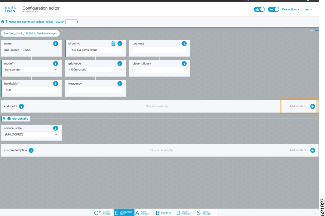
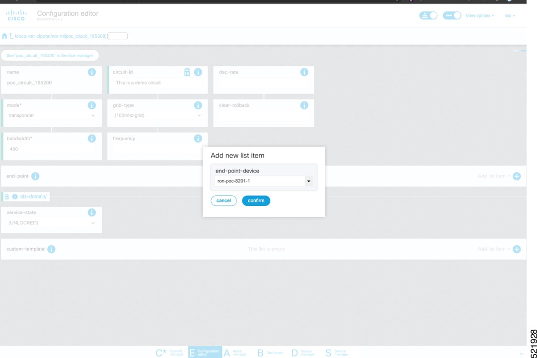
After the ols-domain is added, you must add end-points to the circuit. Two end-points are always required. The end-points are the routers with ZR/ZR+ optics.
-
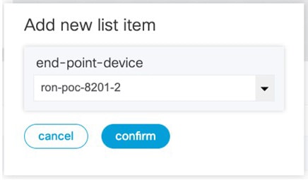
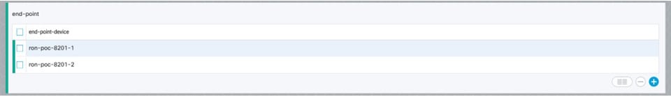
Add the end-point-device to the service. Click Confirm.
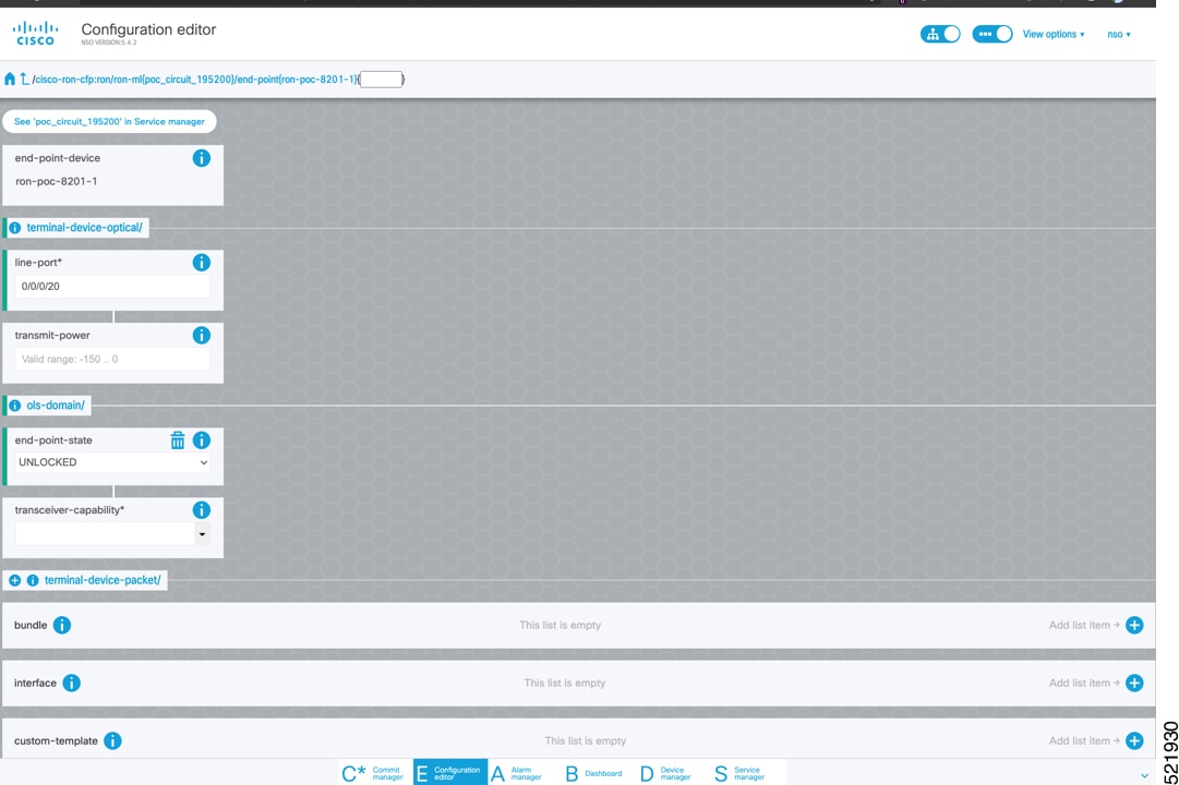
After the end-point is created, click the end-point to edit the end-point parameters. The line-port is a required parameter and refers to the optics port on the router. In this example, this is the same as the line-port specified in the inter-layer-link service for the end-point router.
The transmit-power is an optional parameter for end-to-end provisioning. If it is omitted the optical controller (Cisco Optical Network Controller) will provide the transmit power. Transmit power sets the transmit power, the value is in 100*value in 0.1dBm increments. For example, –100 is -10dBm. If no value is specified the default of -10dBM is used for QDD-400G-ZR-S or QDD-400G-ZRP-S, or 0dBm for DP04QSDD-HE0 (Bright ZR+). The transceiver-capability field specifies the optic type and is only required if no packet layer configuration is being performed. In this example, you are performing packet layer provisioning so specifying the transceiver capability is not required.
Add the line-port of 0/0/0/20 to the Routed Optical Networking ML service.
-
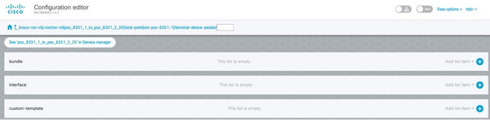
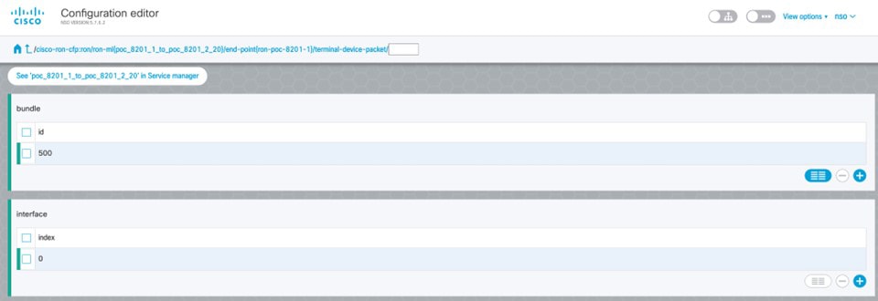
Click end-point to go back to the top-level endpoint configuration, click terminal-device-packet to configure Ethernet/IP parameters
Note
-
Ethernet/IP configuration is optional.
-
Bundle configuration adds an interface to an existing bundle or creates a new bundle and adds the newly created IP interface to it.
Interface configuration is used for configuring IP address parameters on newly created Ethernet interfaces.
In this example we add a new Bundle and assign an IP address to the Bundle.
-
-
Click the plus sign next to bundle to add a bundle, in this case with an identifier of 500. This creates a bundle interface Bundle-Ether 500 on the endpoint router
The interface index for a bundle use case is always 0. In case of a non-bundle configuration in muxponder mode, the index can be 0–3 representing the number of interfaces created as part of the muxponder configuration.
-
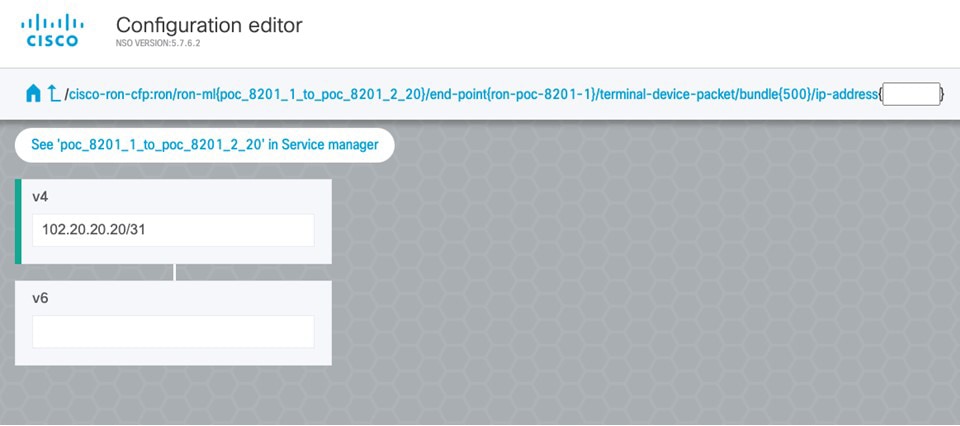
Click the bundle number and ip-address to configure an IP address on the bundle.
-
Return to the top-level endpoint configuration, select the index 0 previously created and click membership to add the interface to the bundle
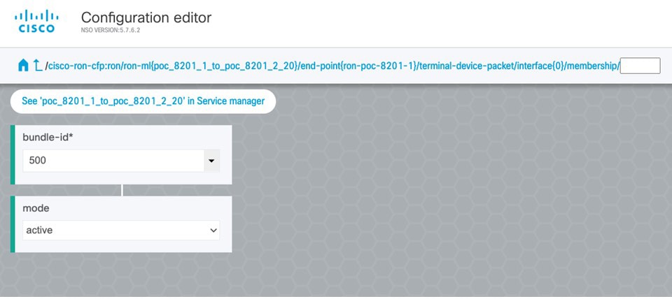
Note
-
Bundle-id selects the previously created bundle.
-
Mode sets the bundle LAG signaling mode. Active=LACP, passive=LACP listener only, on=No active signaling, inherit=Inherit signaling from Bundle interface configuration. Default is active.
-
-
Return to the top level of the service configuration and similarly configure the second endpoint.
-
Click SRLG to perform SRLG configuration
Note
-
Configuration options are to specify a preconfigured group, a list of numeric SRLG values, or a list of SRLG names associated with preconfigured name:value pairs.
-
Each type can be populated in the same configuration.
-
In this example we specify a list of explicit numeric values. An index is used along with the numeric value.
-
-
-
In the Commit manager, click the config tab. The NSO CLI configuration for the end-to-end service is displayed. If the ols-domain component is not specified in the global configuration, no optical line system provisioning is performed, only router provisioning. You can preview and then commit the configuration.
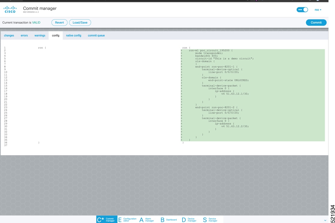
-
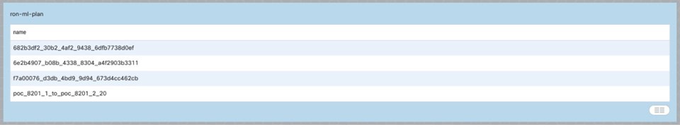
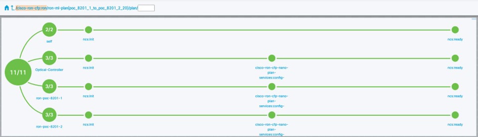
Verify status in NSO UI.
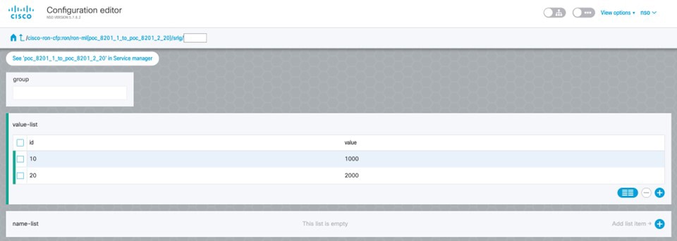
You can verify the status by inspecting the plan associated with the service. You can find the plan under the main ron-ml configuration which you can access by clicking the top portion of the service configuration. An example is highlighted in the following image.
-
Inspect the plan by clicking on the newly created service
If all steps are green and complete, the service has been properly deployed to the network
-
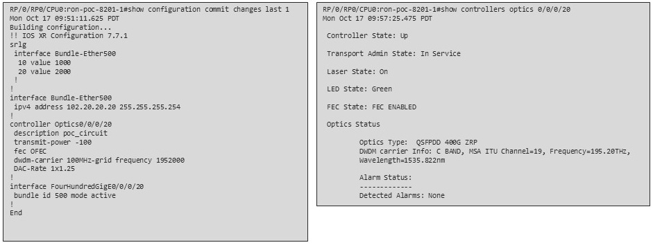
Inspect router configuration.
The show configuration commit changes last 1 command shows the CLI config applied to the device during the NSO provisioning.
The show optics controller 0/0/0/20 command verifies the operational status.
-
Provision Routed Optical Networking ML Service Using Crosswork Hierarchical Controller
-
If you are performing both router and optical line system provisioning, you must create NMC Cross Links between router optics port and optical line system add/drop port.
Crosswork Hierarchical Controller 8.0 in Routed Optical Networking 3.0 also supports “router only” provisioning which provisions optical parameters on router optics port and IP layer parameters but does not provision OLS.
-
Select Link Manager application.
Figure 32. Crosswork Hierarchical Controller 
You get the following initial view that shows the list of Cross Links.
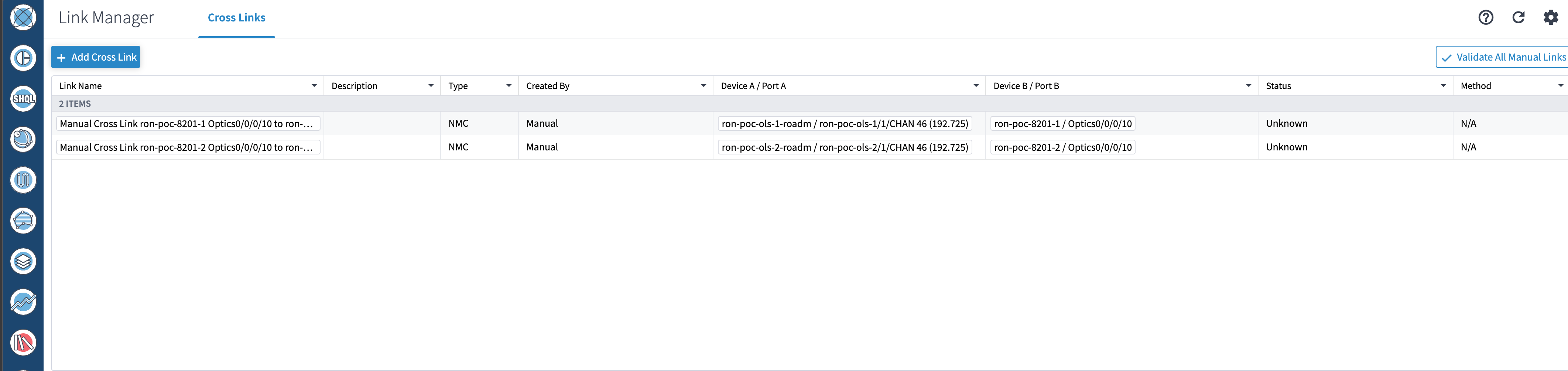
-
Click Add Cross Link.
Figure 33. 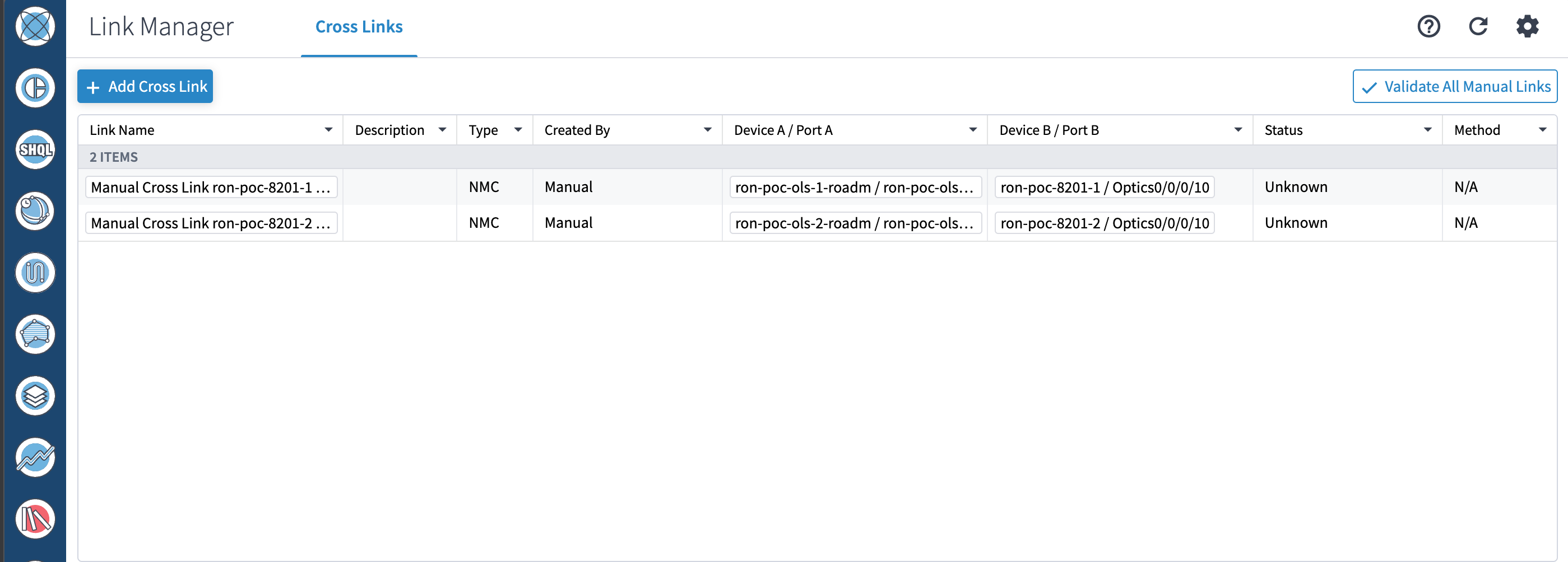
-
Select the NMC cross link type. Cross Link Manager supports ETH and NMC cross links.
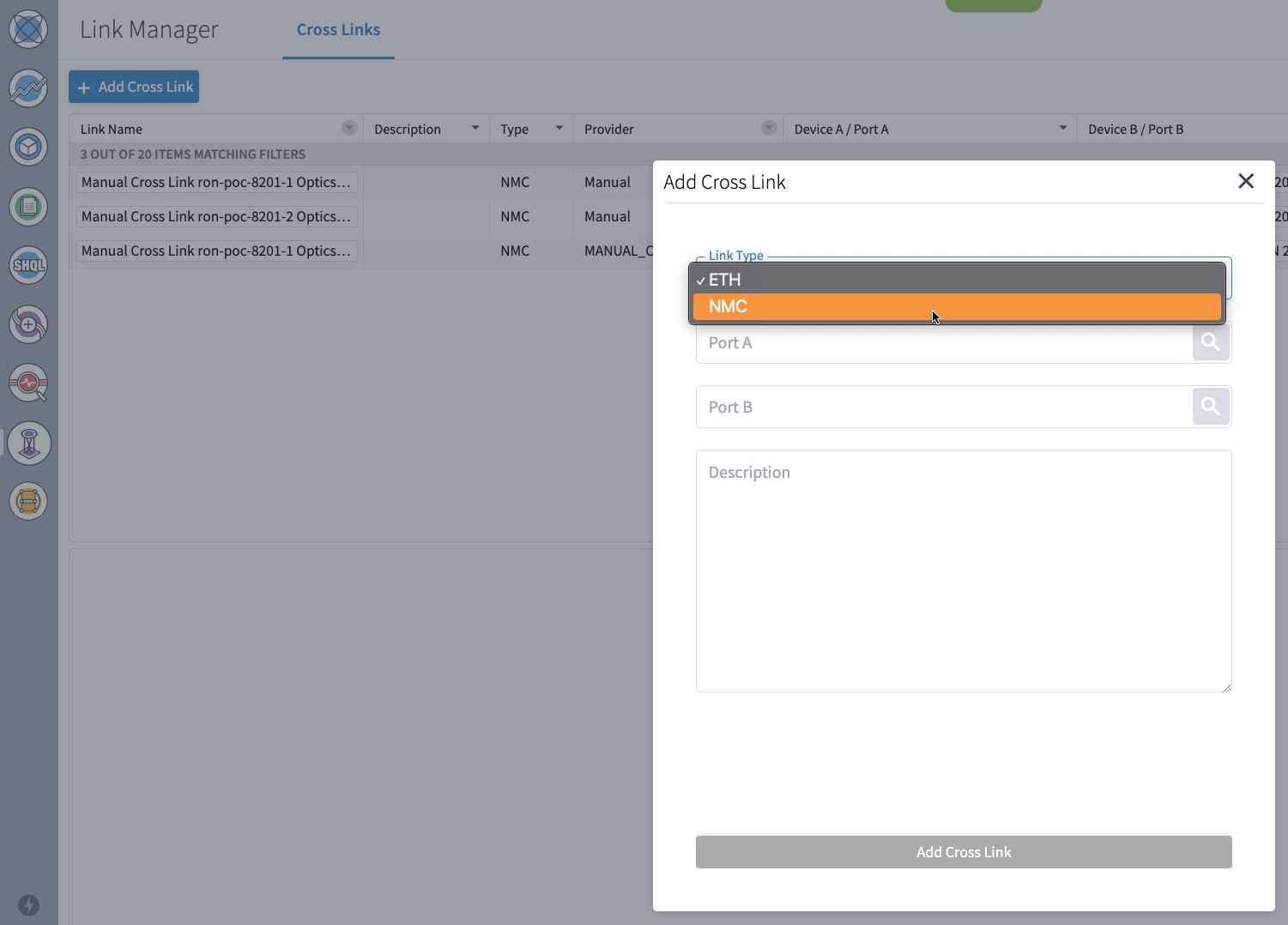
-
The Link Manager application allows you to select either router DCO port or optical add/drop first. In the following image we filter the ports by the router device that we use for our NMC cross link.
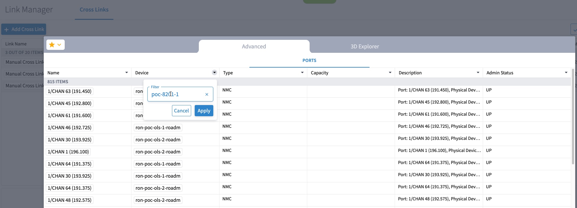
-
The following image shows the filtered list. Our router, ron-poc-8201-1 has a single ZR+ optics port, select the port and click OK

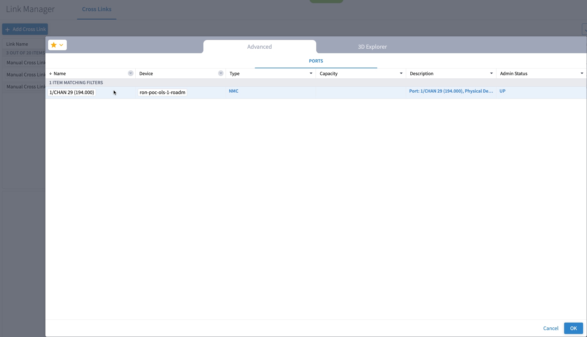
-
Like in the previous step, select the second port which is the optical add/drop port. Filter by device as ron-poc-ols-1 and the Name as 194.000 to filter to the add/drop port
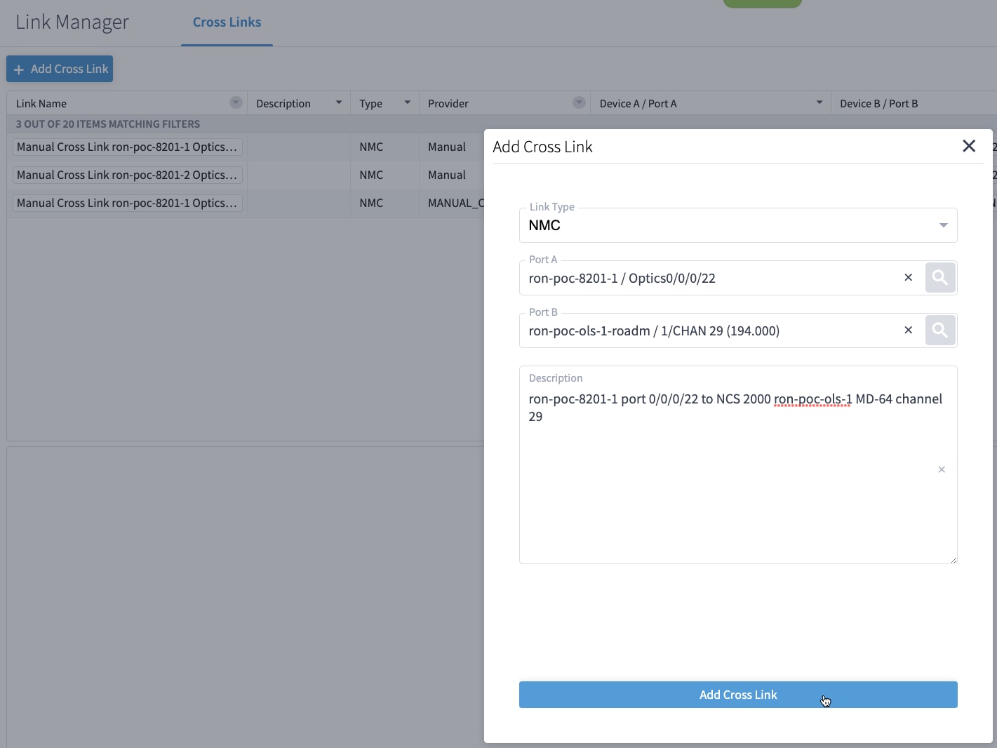
-
Select the two ports (Ethernet and OCH) in your NMC Cross Link. Click Add Cross Link.
(Optional) Add a description
-
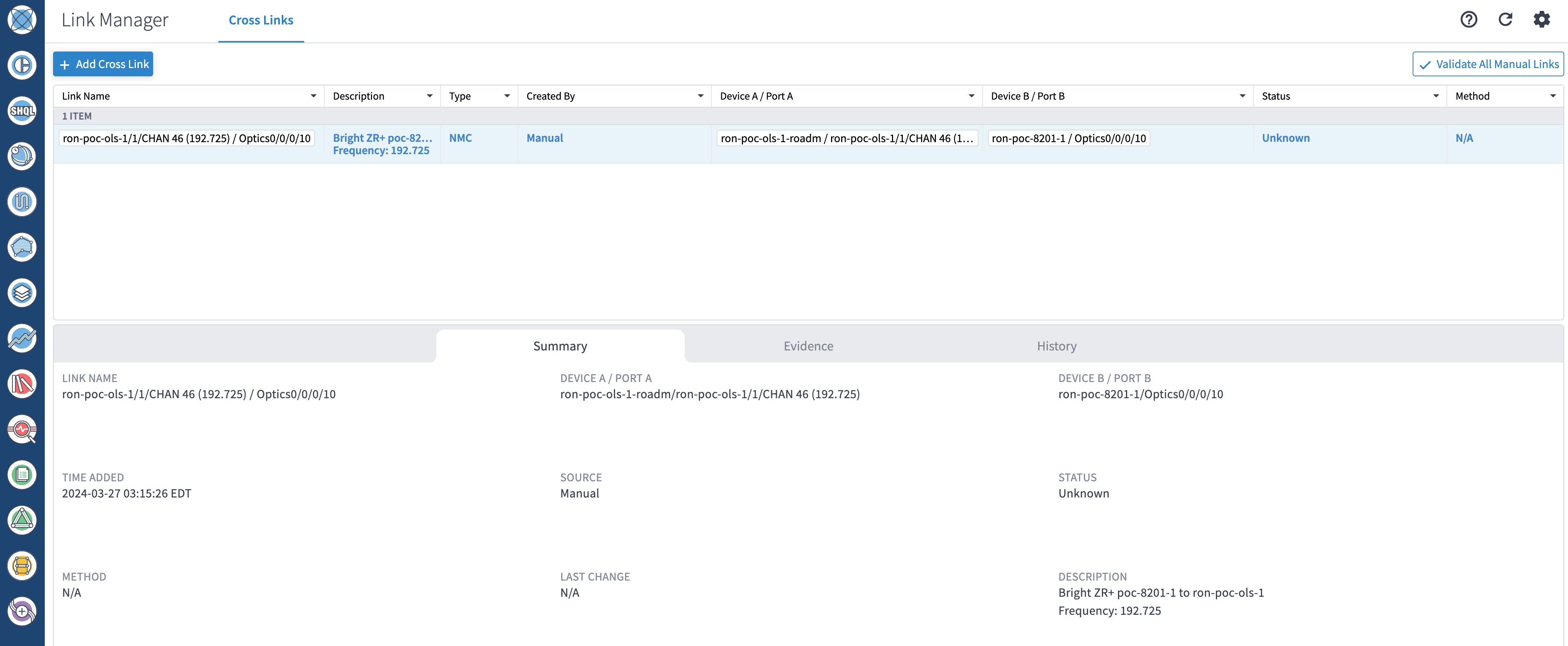
Click the added cross link to see its attributes.
-
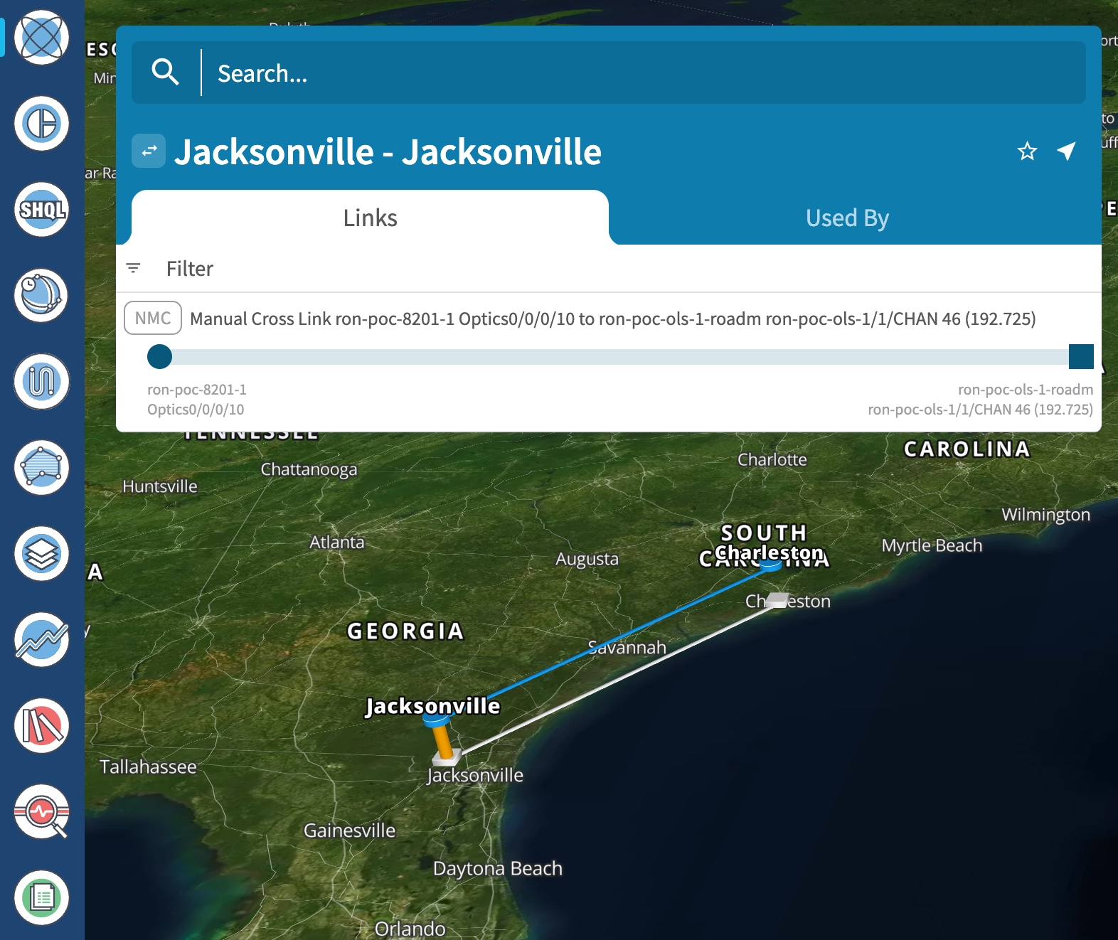
View the added crosslink in the explorer app by clicking on the link.
-
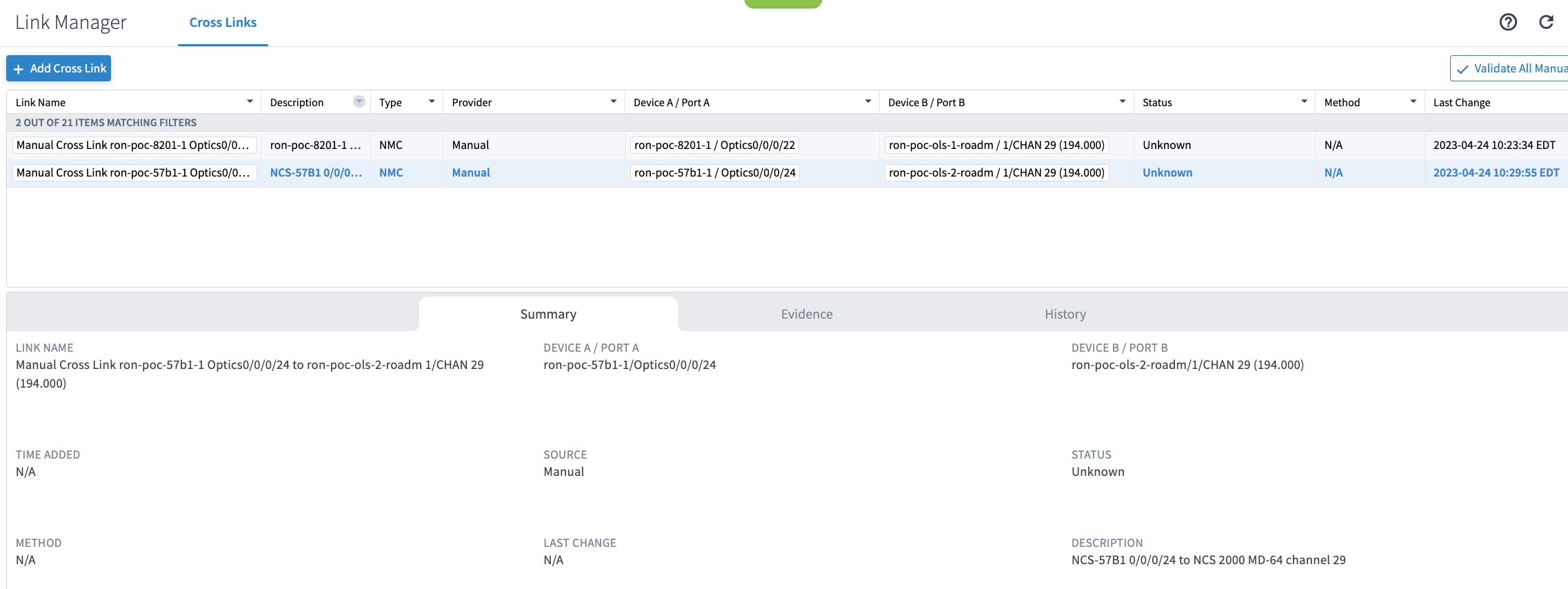
Similar to the previous steps, create the second NMC cross link.
-
View the end-to-end network with both crosslinks in the Explorer app.
-
-
(Optional) Cross-Link Connectivity Verification
-
Cross-Link Connectivity Verification is supported on all router platforms and NCS 1010 with MD-32 and BRK-24 modules.
-
Connectivity Verification uses NSO CLI NED to modify router port state and TX power, is service affecting.
-
When validation starts, Hierarchical Controller continuously checks the RX power on the optical add/drop port. Connectivity Verification is performed in the background.
-
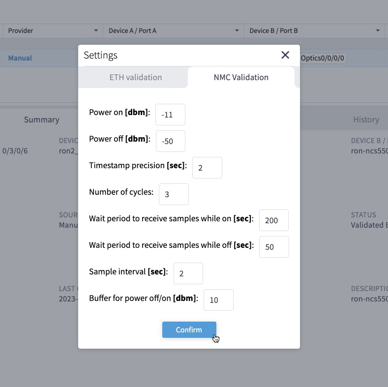
Configure NMC Validation Settings. Settings are used to control validation, Wait period to receive samples while on must be set to 180 seconds, Wait period to receive samples while off must be set to 50.
-
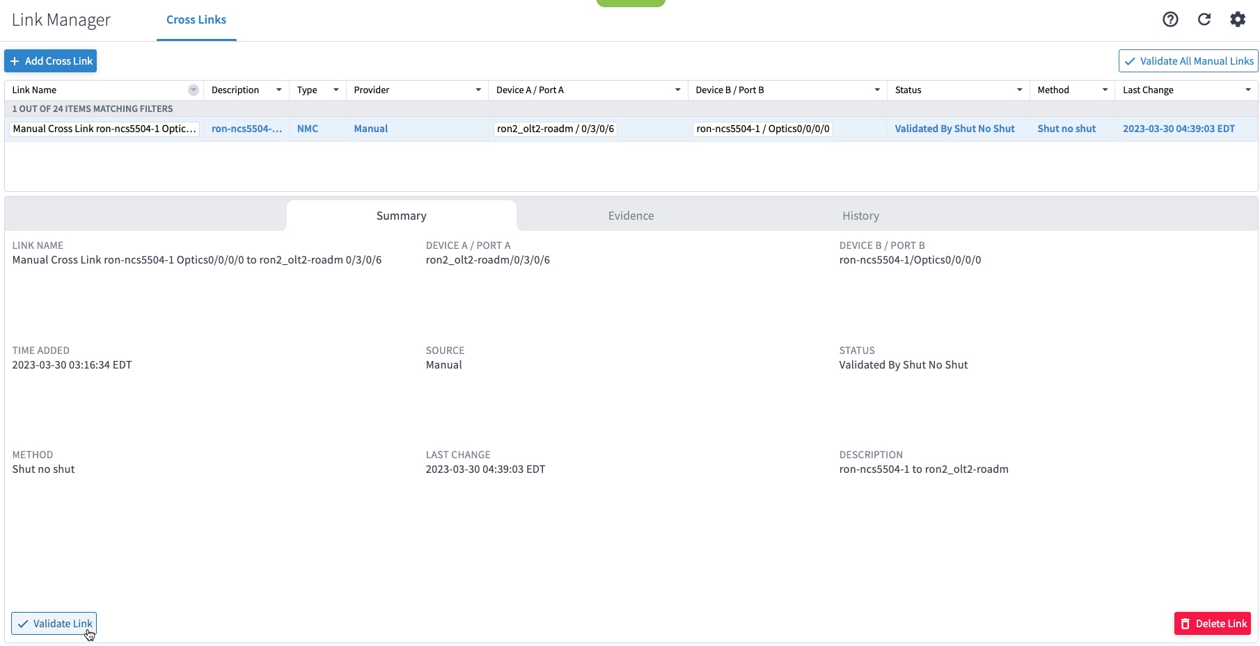
Select a link and click Validate Link. Alternatively, you can click Validate All Manual Links to perform connectivity verification for all links.
-
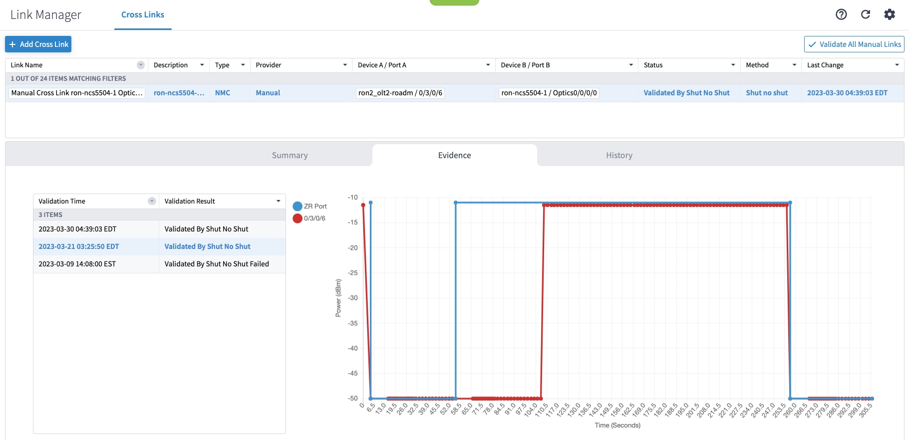
After validation completes, inspect the evidence of either successful or unsuccessful verification. The following image shows a successful verification. Status changes from Unknown to Validated By Shut No Shut. The time it takes for the ZR/ZR+ to start transmitting after no shut is set is typically 60–80 seconds.
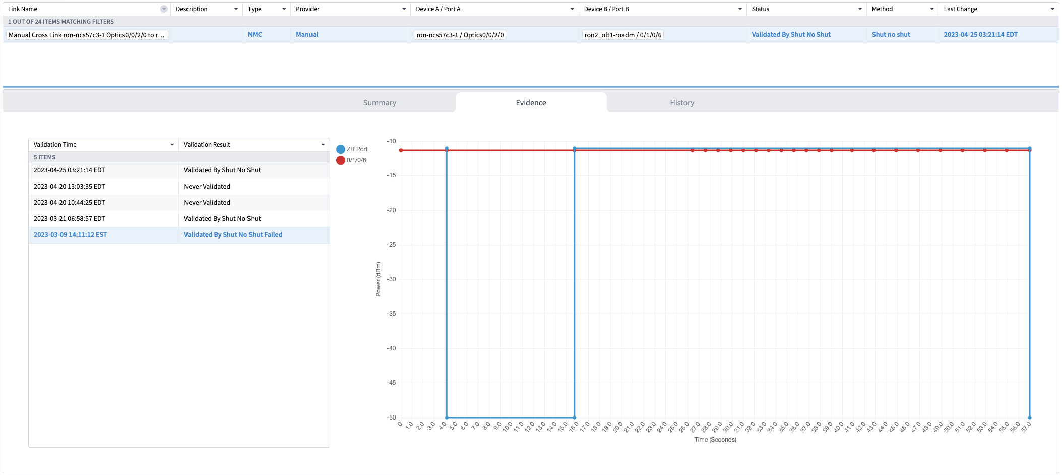
The following image shows a failed verification. There is no change in the optical device port power levels after the no shut operation
-
-
To provision the Routed Optical Networking IP link, perform these steps:
-
In the applications bar in the Crosswork Hierarchical Controller, click the Services Manager icon.
The Service Manager Application shows you a list of services.
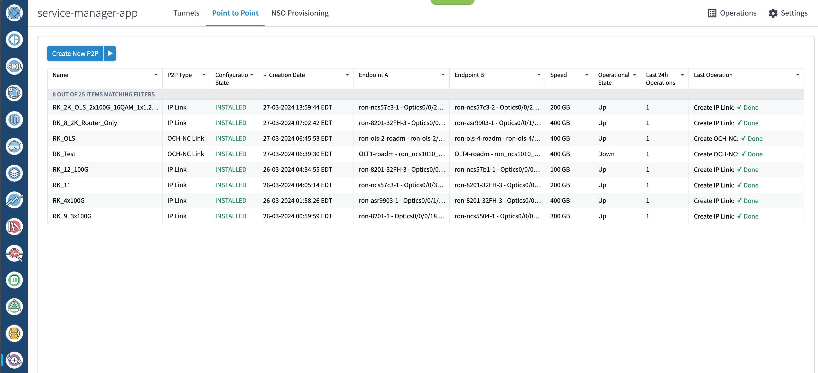
-
Select the Point to Point tab and click IP Link from the Create New P2P drop-down list to create end to end service between router DCO ports.
The IP Link Creation wizard appears.
-
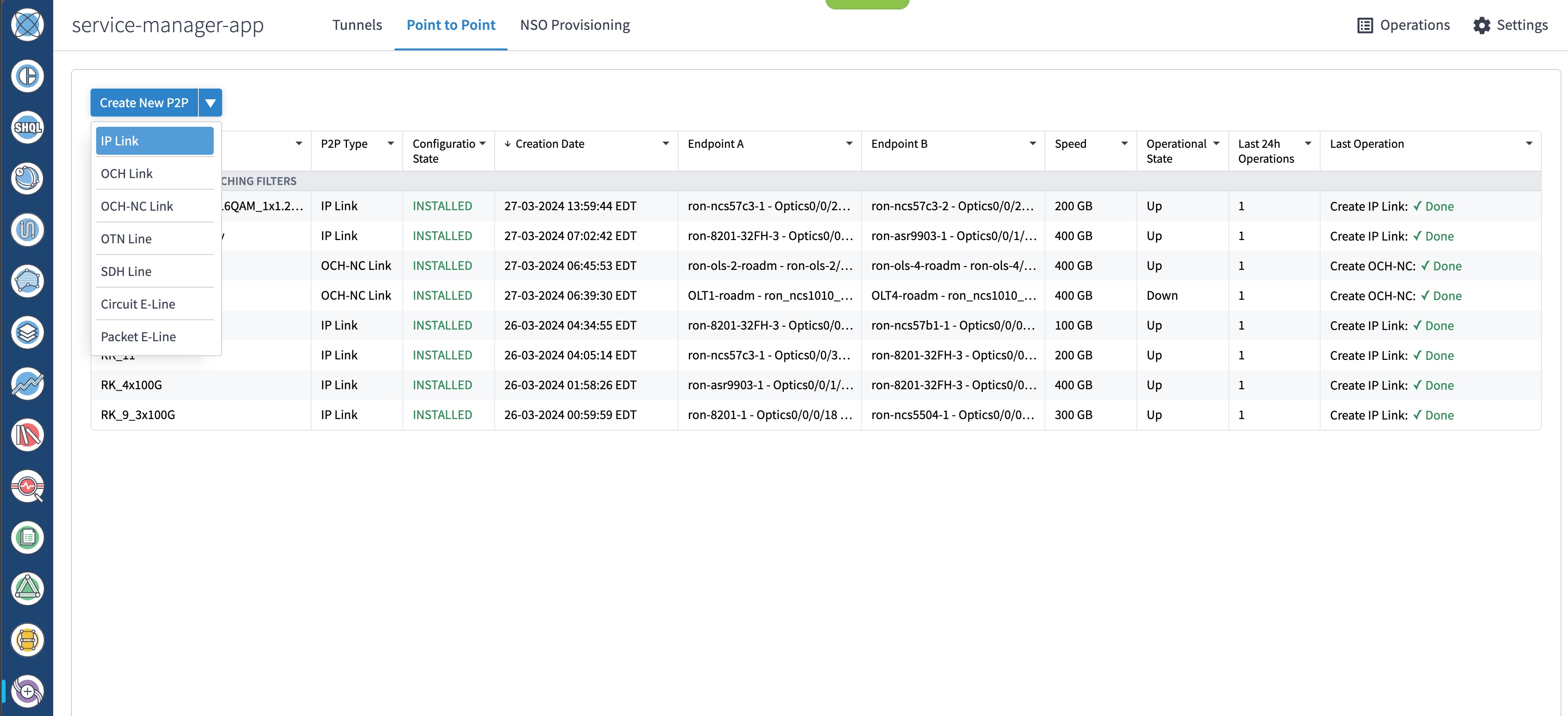
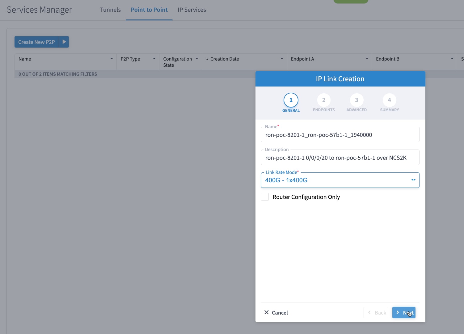
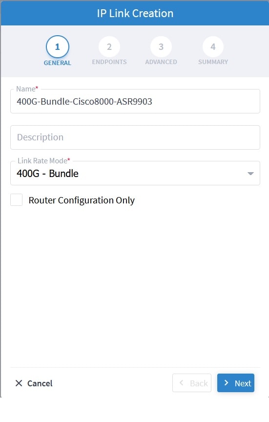
Enter the Cisco Crosswork Hierarchical Controller service name, description of the router optical controller, and the Link Rate Mode in the General tab.
-
Here, we are creating a 1x400G link. In 2x100G, 3x100G, and 4x100G modes, you can choose to create separate IP links or create a Bundle with each channel link added as a member.
-
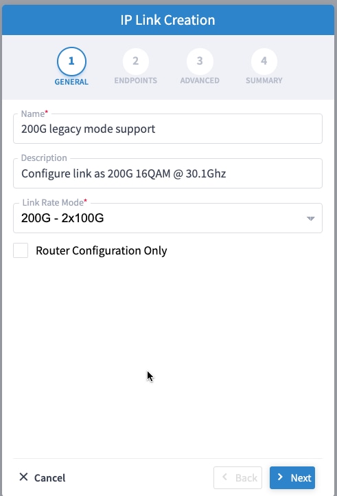
To create a 200G 16-QAM link, Select the 200G – 2x100G link rate mode.
200G 16-QAM allows the use of 200G signals on 50Ghz optical line systems. Default for 200G is QPSK at 60.1Ghz.
-
To create a Bundle interface, Select a bundle option from the link rate mode drop down list.
You can create a 400G bundle interface (400G Member). Alternatively, 300G-bundle (3X100G Members) and 200G-Bundle (2x100G Members) can be created
(Optional) Check the Router Configuration Only check box to configure only the router optical controller and IP information and not the optical line system. This configuration is used when the OCHNC is created outside Cisco Crosswork Hierarchical Controller.
-
-
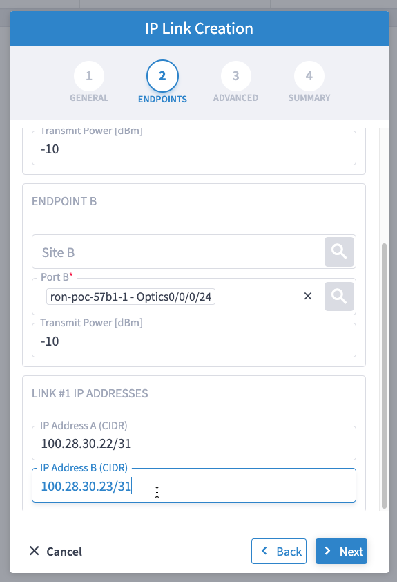
Select the two router ports in the service. This is done by selecting the Site and Port. The transmit power for each endpoint is an optional parameter. The default TX power is used if no value is provided.
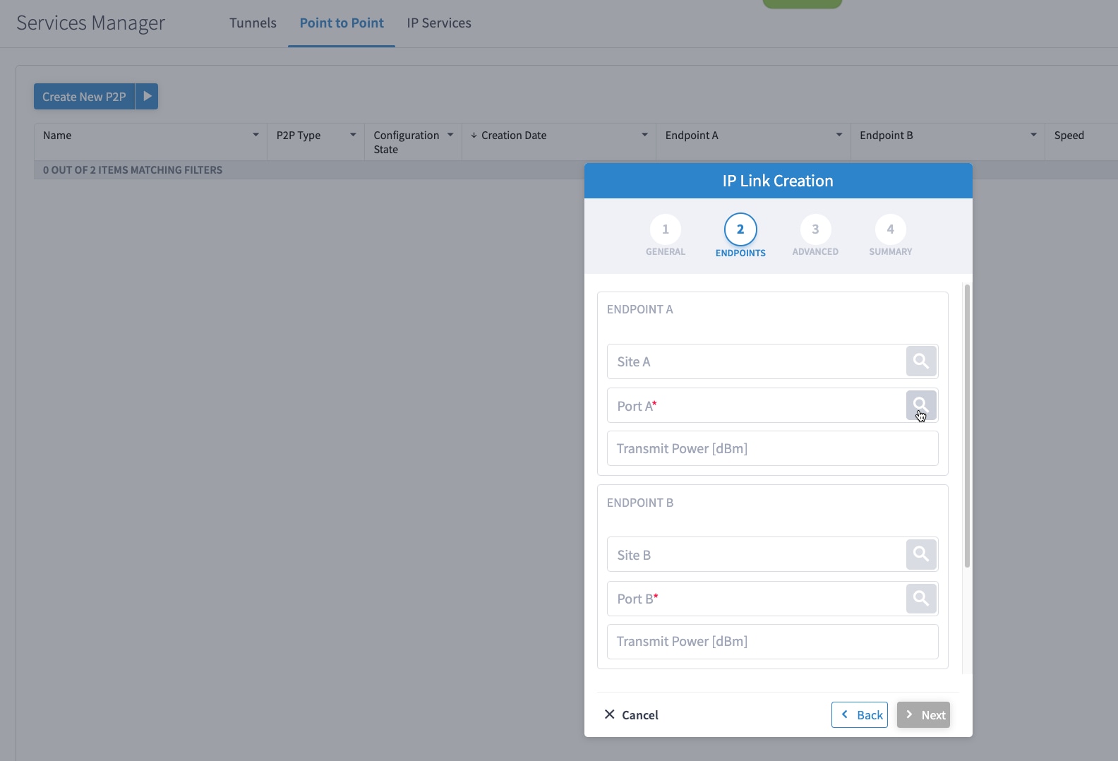
-
Click the magnifying glass icon to select the first router port.
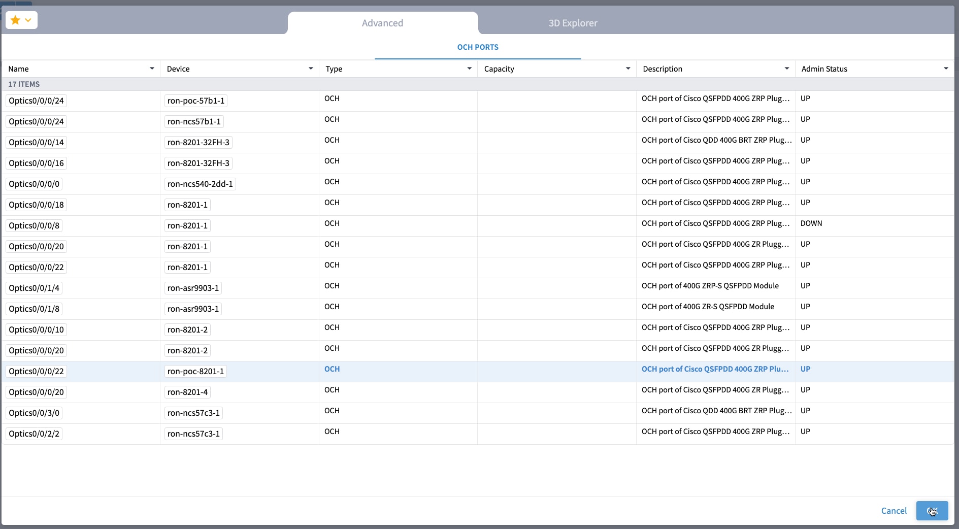
The ports are displayed based on the following criteria:
-
Is a ZR/ZR+ interface
-
Has no existing optics configuration
-
Has a proper NMC cross-connect configured
This page lists all available ZR/ZR+ ports currently unused on all devices. Select the ron-poc-8201-1 Optics0/0/0/22 port.
-
-
Similar to the previous step, choose ron-poc-57b1-1 Optics 0/0/0/24 as the second router port.
-
(Optional) Set the transmit power in dBm on each port. If OLS provisioning is being performed, the OLS controller returns the optical power. If the OLS controller does not return the optical power or router only provisioning is being used, the router default power is used.
-
(Optional) Enter the IP address information for interfaces. If IP addresses are not entered, ZR/ZR+ router optical configuration happens; however, IP addresses are not configured.
-
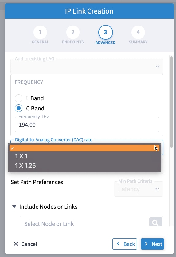
Click Next to move to Advanced configuration.
-
(Optional) Set the Frequency. If optical provisioning is being performed, the OLS controller can return the frequency to be used, and it may be omitted. If router only provisioning is being performed, the Frequency must be specified.
-
(Optional) Set the DAC rate. A DAC rate setting can be used to enable OpenZR+ compatibility mode, disabling TX shaping and enhanced modem mode. See OpenZR+ Compatibility Mode for more information on mode support.
-
(Optional) Set links or nodes to include/exclude in the optical path. This setting is not available in router only provisioning.
-
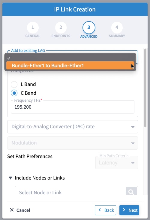
(Optional) To add the new link or set of links to an existing Bundle LAG interface configured on the routers, choose the bundle from the Add to existing LAG drop-down.
-
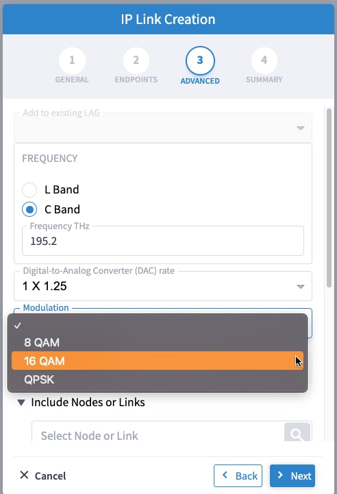
(Optional) If you are configuring a 200G 16-QAM link, set the DAC rate to 1x1.25.
200G link rate mode enables the Modulation selection drop-down. Modulation selection is not available in any other mode. Select the16 QAM (30Ghz) modulation.
-
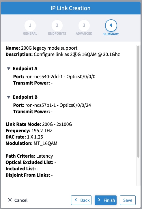
Click Next to review the final configuration. Verify the router endpoint and optical line system parameters. Click Finish to start provisioning, or click Save to save for later provisioning.
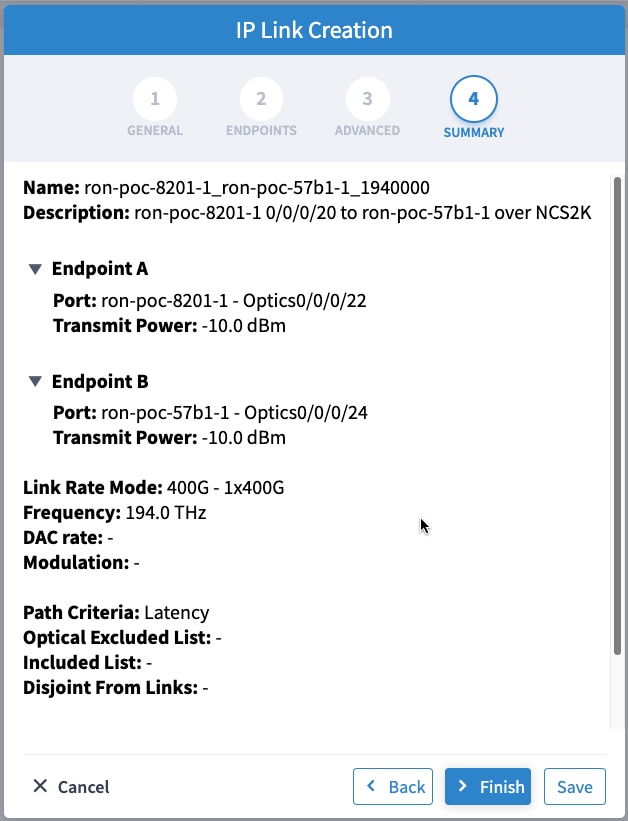
The following image shows a sample summary for a 200G 16-QAM link.
-
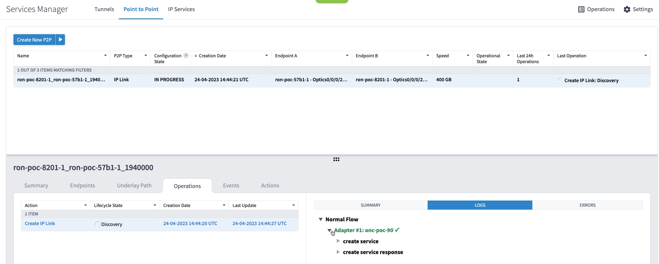
Go to Services Manager to view provisioning progress.
Click the tab to view the provisioning API calls used and responses. The logs show API calls and responses for both optical line system provisioning via Cisco Optical Network Controller and router provisioning via Crosswork Network Controller.
If the provisioning is successful, the Configuration State field changes to INSTALLED state and the Operational State field changes to UP state.
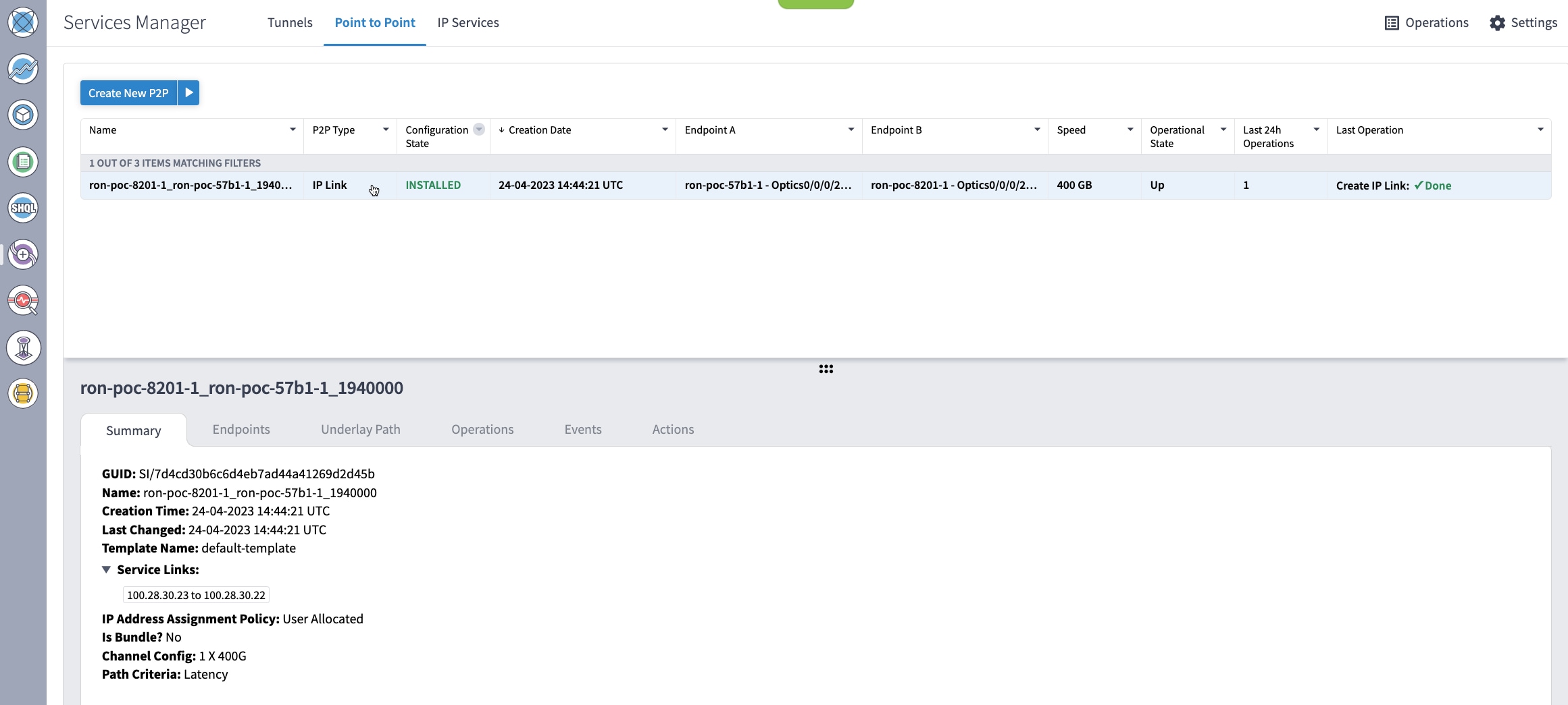
The Summary tab displays the new service link.
-
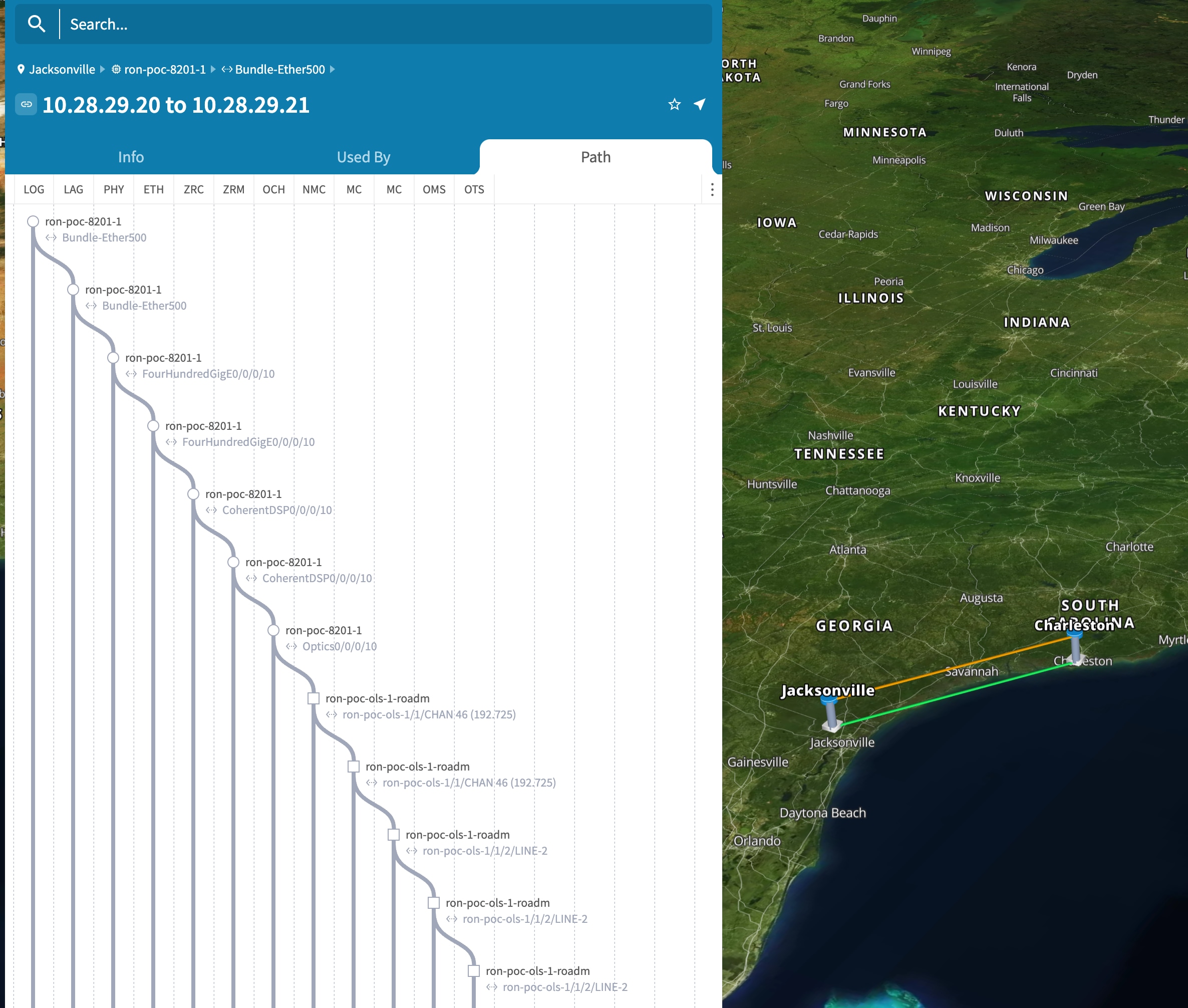
Verify the end to end link across both IP and optical layers in the Explorer view.
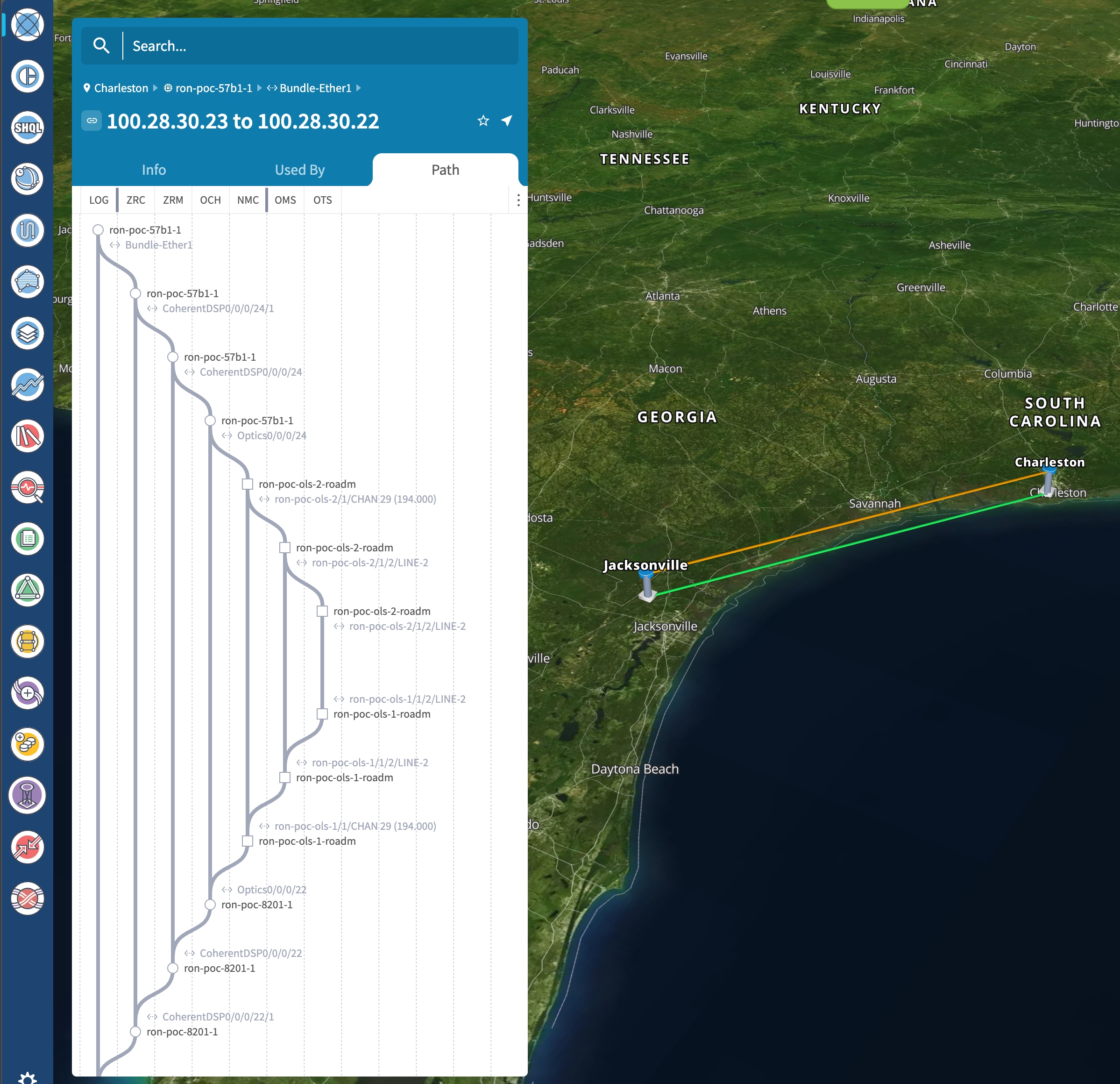
-
-
Use the Link Assurance application to verify the end to end path and relevant PM data. Select a link or port to see data on the ZRM, OCH, and OTS layers.
Operate Phase
To monitor the ZR/Z+ optics:
-
Use either CLI commands or EPNM to monitor router ZR/ZR+ optics for proper operation. See Monitor ZR or ZR+ Optics Using EPNM.
-
(Optional) Setup router ZR/ZR+ optics data collection in CW Health Insights. See Monitor Performance of ZR/ZR+ Optics Using KPIs.
To monitor NCS 1010, use Cisco Optical Network Controller and Cisco Optical Site Manager:
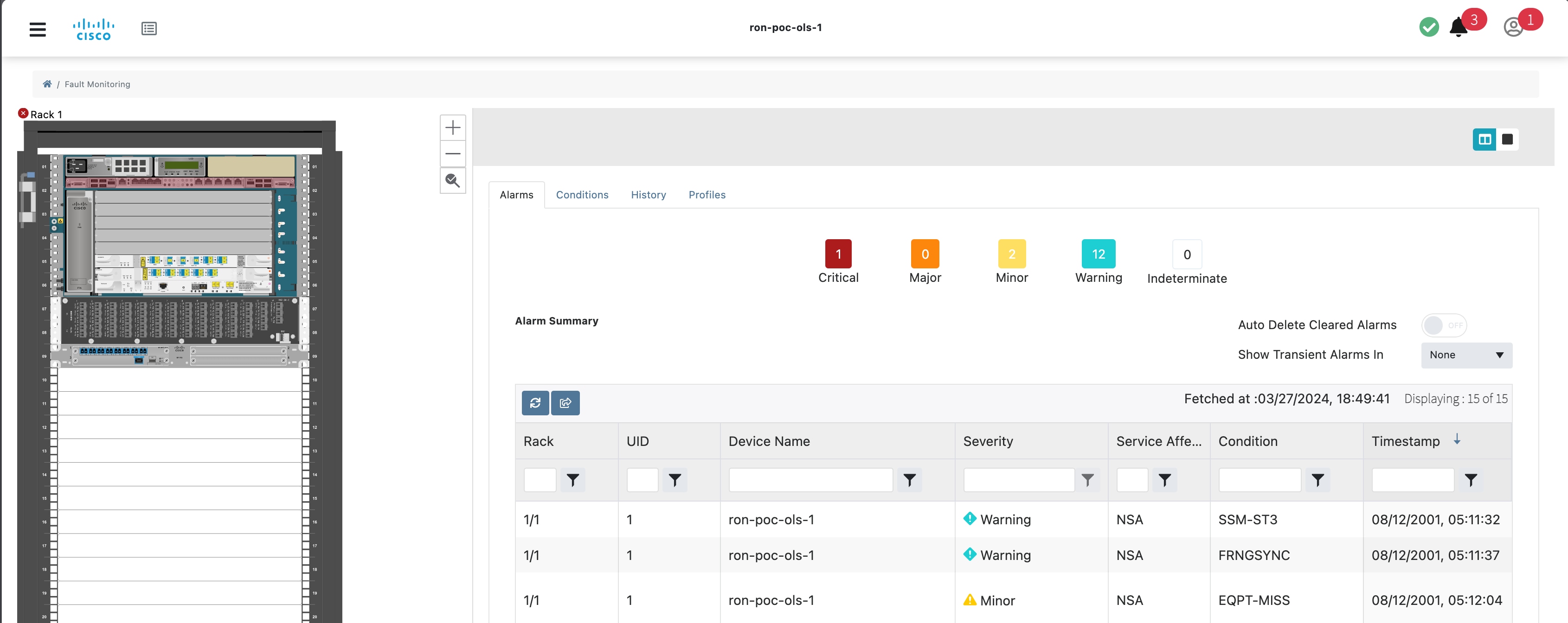
Monitor ZR or ZR+ Optics Using EPNM
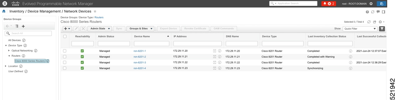
This section adds the 8201 router to EPNM for monitoring the PM parameters on the ZR or ZR+ optics.
-
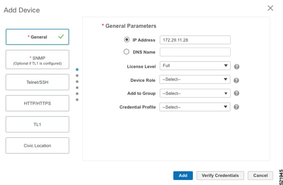
To add a new device to EPNM choose Inventory > Device Management > Network Devices. Click Routers or a subgroup if it is already defined in the left panel.
-
Click the
 icon above the Network Devices table, then choose Add Device.
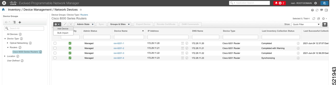
-
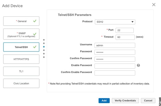
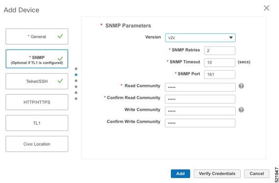
Configure the General, SNMP, and SSH parameters as seen in that following figures. Click Verify Credentials to validate that Cisco EPN Manager can reach the device. Click Add to add the device to EPNM.
-
To open the chassis view from the Network devices table, click the device name link. The following figure displays the chassis view of the 8201 router.
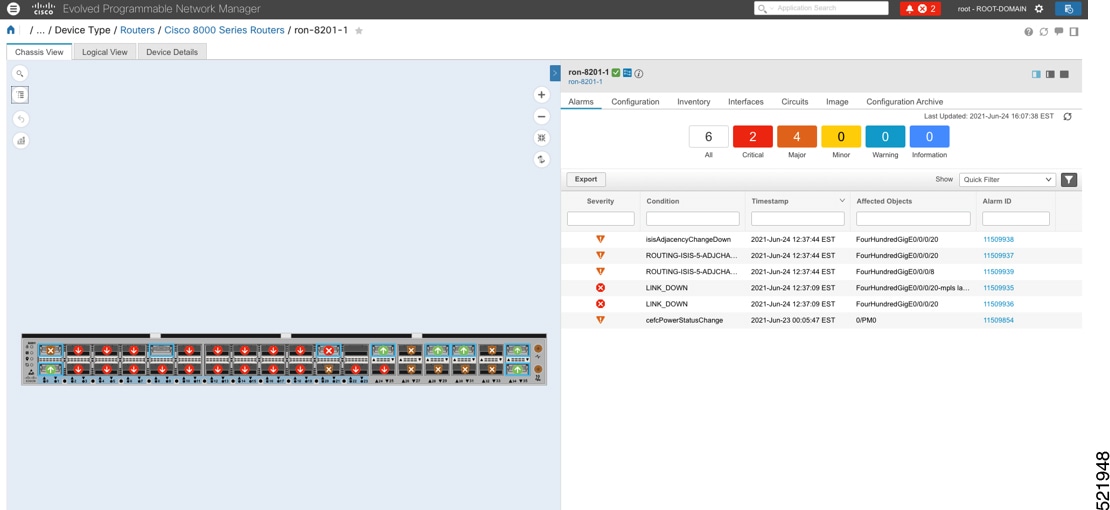
-
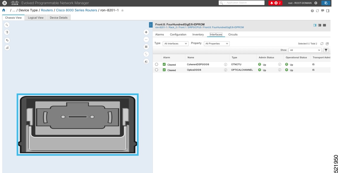
Click the QSFP-DD ZR+ port to see specific data about that port.
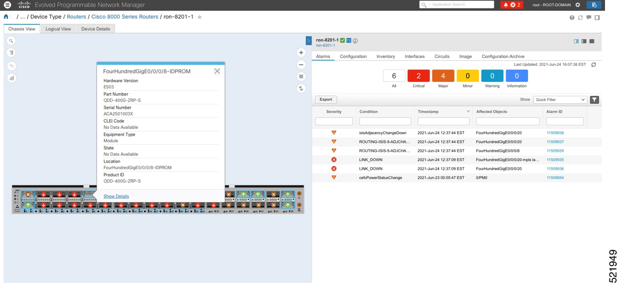
Here you can view the port and specific optical channel and CoherentDSP entities.
-
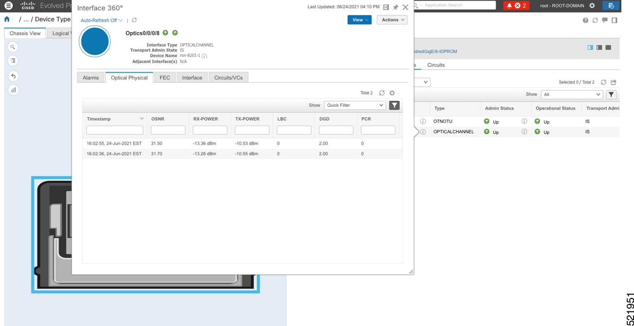
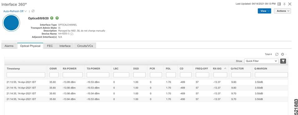
Clicking the additional information icon for the optical channel and then the Optical Physical measurement tab displays the relevant optical PM values such as RX/TX signal power and OSNR values.
-
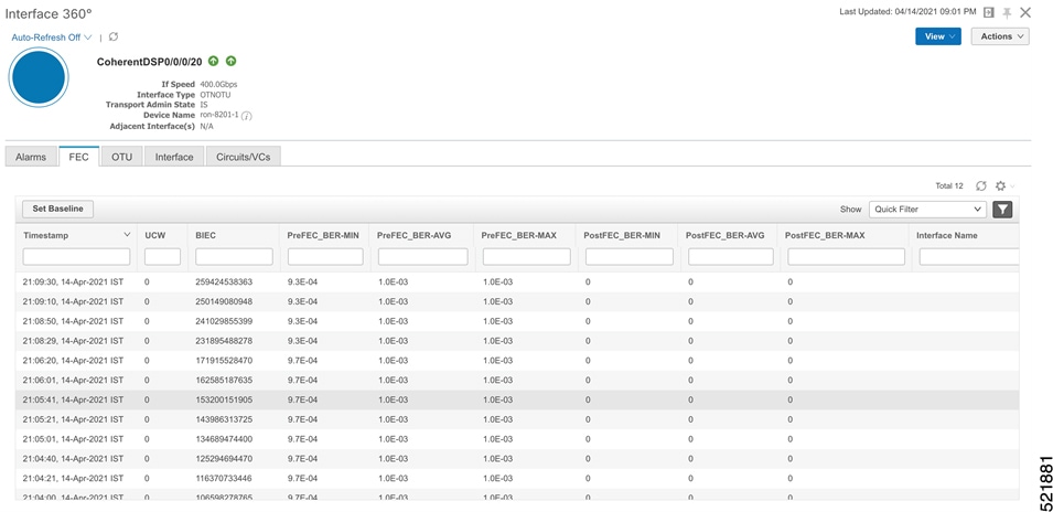
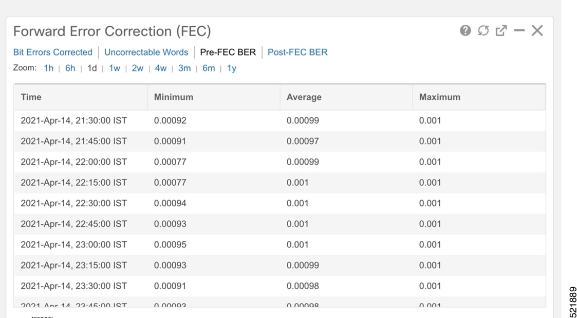
Clicking the additional information icon for the coherent DSP and then the FEC measurement tab displays the relevant coherent DSP FEC statistics such as PreFEC Bit Error Rate, Bit Error Rate Count (BIEC), and Uncorrected Words (UCW). The UCW value must remain 0.
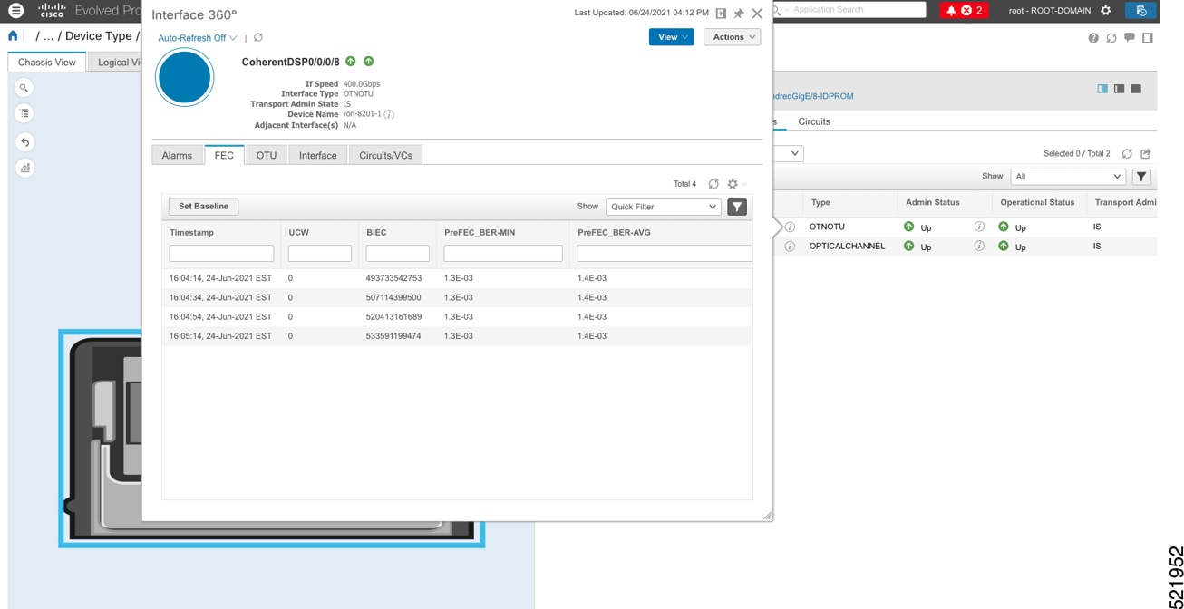
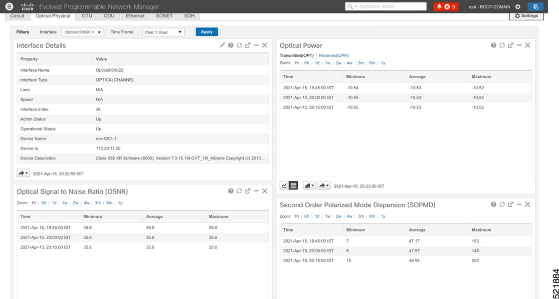
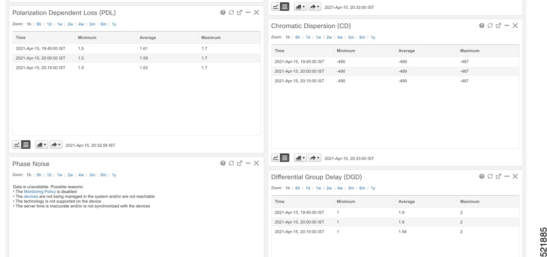
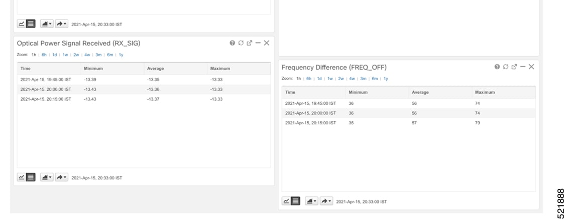
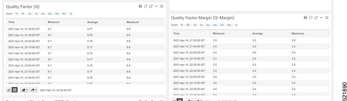
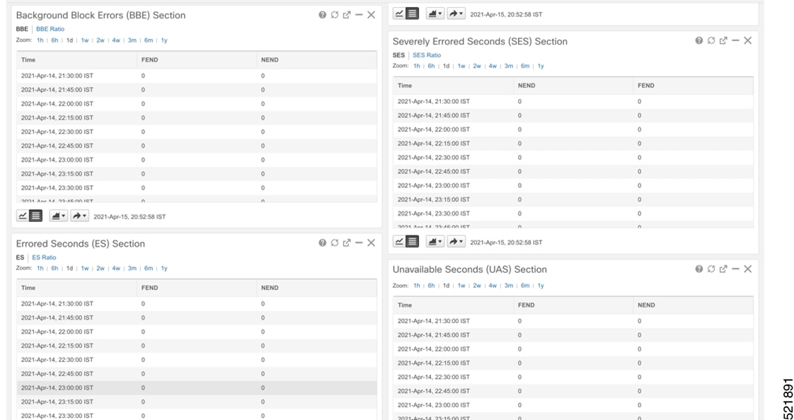
The following figures display the current and historical performance monitoring data in EPNM that is specific to the ZR or ZR+ optics.
Monitor Performance of ZR/ZR+ Optics Using KPIs
Perform the following steps to create KPI Profiles in Health Insights and enable them on the devices to monitor network health.
Note |
Plan which Cisco-supplied KPIs you want to begin using, based on each device's function and the device performance characteristics you want to monitor. Review the Cisco-supplied KPIs documented in List of Health Insights KPIs. In the following image, you see the available default L1 optics KPIs. 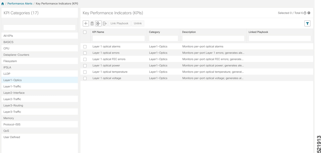 |
-
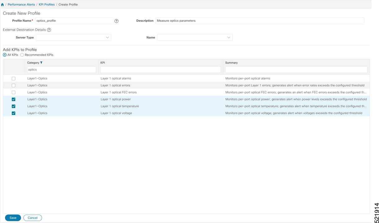
Group the relevant KPIs to form a KPI Profile. A KPI profile can have many different KPIs assigned. In this case, the focus is only on some specific optics KPIs to add to the optics_profile KPI profile.
-
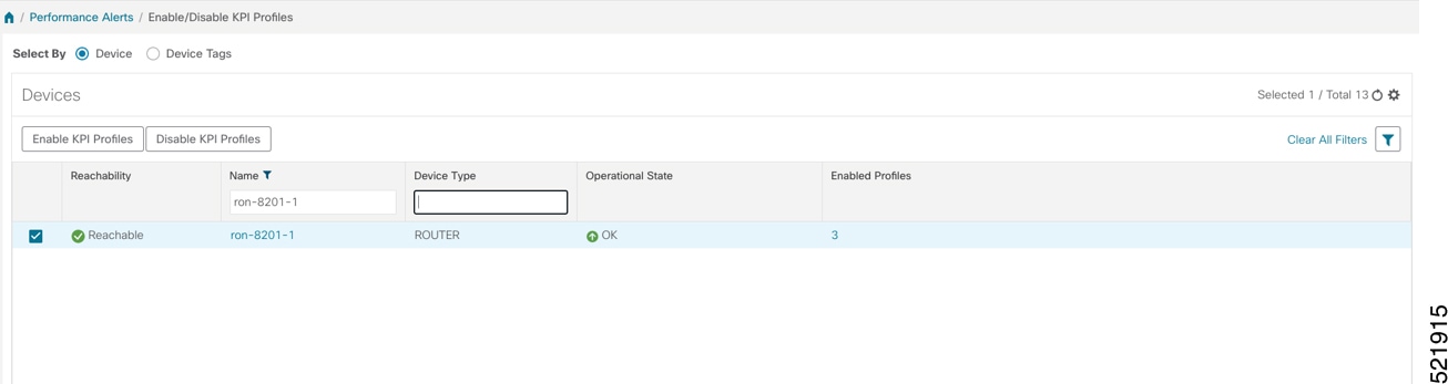
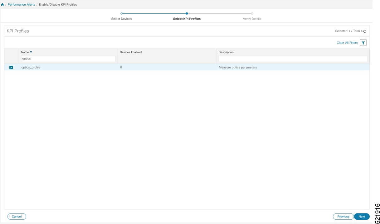
Enable the appropriate KPI Profiles on the devices you want to monitor. From the main menu, choose Performance Alerts > Enable/Disable KPI Profiles. Check the checkboxes of all the nodes to which the profile must be applied to, and click Enable KPI Profiles.
Multiple nodes may be selected. In the following figure, we are applying the KPI profile to a single node.
-
Select the optics_profile KPI profile that was created in the previous step and click next to finalize enabling the KPI for the selected device.
-
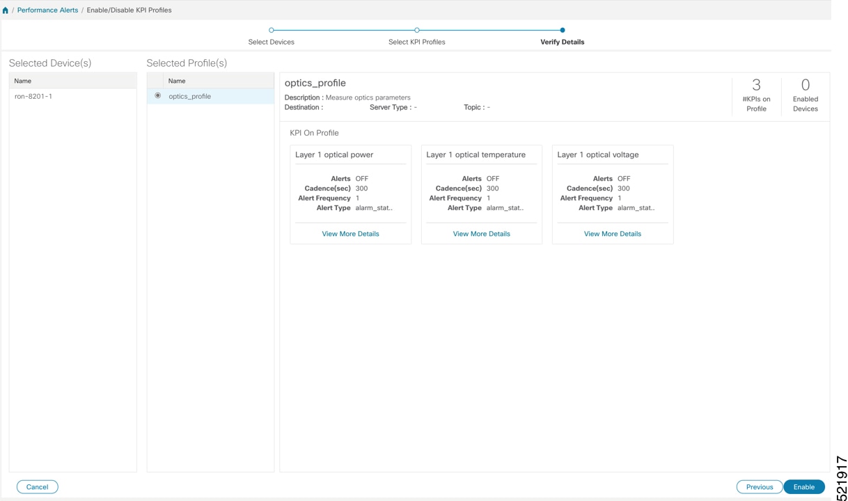
The following image displays the final page before enabling the KPI profile for the router. After you click Enable, the appropriate configuration is applied to the router to begin streaming the telemetry sensors data for the selected optical KPIs.
-
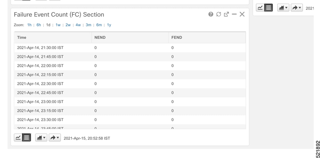
To view alerts from network devices, see View Alerts for Network Devices.
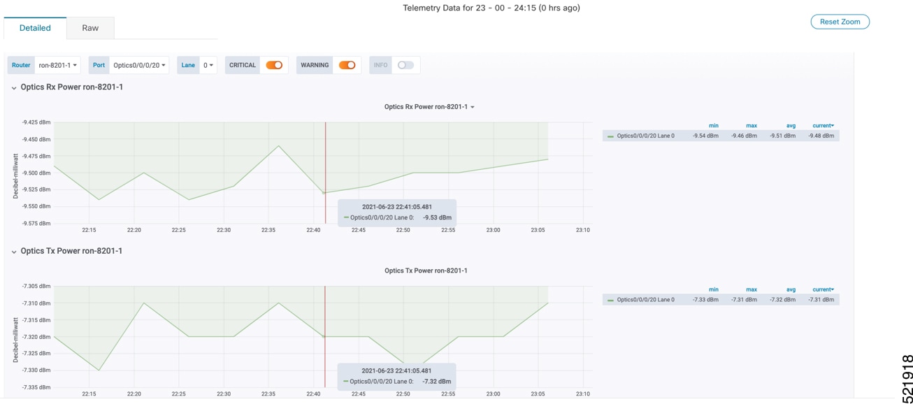
The following figure displays the RX and TX power of the QDD-400G-ZR-S transceiver.
Optimization Phase
The optimization phase involves:
-
Return to planning stage.
-
Continue to add or change circuits on the network to match packet demands.
 Feedback