Sequence for Installation of Routed Optical Networking Components
We recommend this installation sequence:
 Note |
Cisco Crosswork Network Controller (Crosswork Optimization Engine, CAT) and Cisco Optical Network Controller are the minimum required components for the Routed Optical Networking solution. |
-
Install Cisco Optical Network Planner. Cisco Optical Network Planner is used to determine the optical layer feasibility and components used to support the network. A BoM is generated for hardware to be utilized in the planned deployment. For more information, see Cisco Optical Network Planner Installation Guide .
-
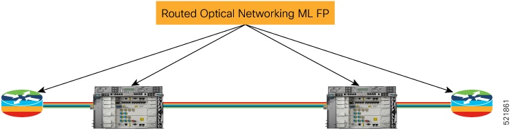
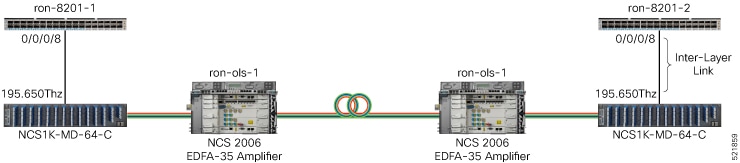
Install the router and optical hardware as specified in the network design. Complete the physical wiring between all the components. For more information see, Deployment Topologies.
-
Install SVO to manage the NCS 2000 optical components. Create SVO instances to manage NCS 2000 devices. For more information, see Cisco NCS 2000 Series SVO Configuration Guide, Release 12.2.
-
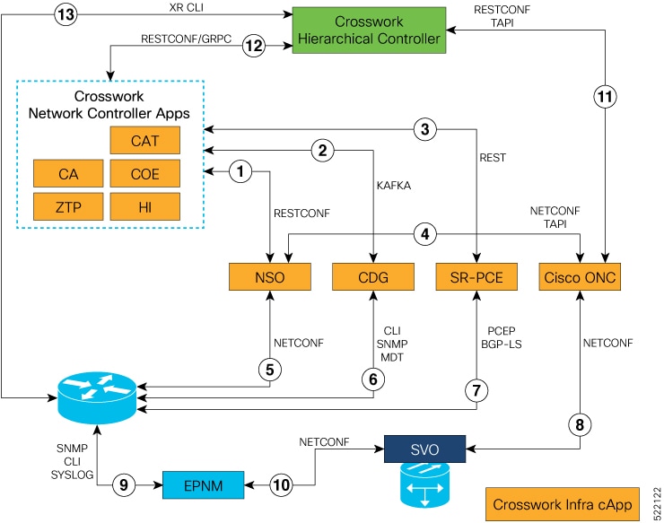
Install the Crosswork Infrastructure 4.0, Crosswork Data Gateway, and supporting Crosswork Network Controller 3.0 applications (Crosswork Optimization Engine, CAT, Hi). For more information, see Cisco Crosswork Infrastructure 4.1 and Applications Installation Guide.
-
Install Cisco Optical Network Controller 1.1. For more information, see Cisco Optical Network Controller 1.1 Configuration Guide.
-
Install EPNM 5.1.3. EMS to manage the physical router and the optical network nodes. For more information, see Installation Guide for Cisco Evolved Programmable Network Manager 5.1 .
-
Install Cisco NSO 5.5.2.9, Routed Optical Networking Multi-layer Function Pack 1.0, and Crosswork DLM function pack. Optionally, install the Cisco Transport SDN Function pack for SR-TE and xVPN service management. For more information, see the Cisco Network Services Orchestrator Installation Guide, Cisco NSO Routed Optical Networking Core Function Pack Installation Guide, Cisco NSO Transport-SDN Function Pack Bundle User Guide 3.0Cisco NSO Transport-SDN Function Pack Bundle User Guide 4.0, Cisco Network Services Orchestrator DLM Service Pack Installation Guide 4.1.0.
-
Add SVO devices to Cisco Optical Network Controller for the optical service management. For more information, see Cisco Optical Network Controller 1.1 Configuration Guide.
-
Install SR-PCE in the network for SR-TE or RSVP-TE discovery and visualization.
-
Add NSO, SR-PCE, and Cisco routers to the Crosswork cluster. For more information, see Add Cisco NSO Providers, Add Cisco SR-PCE Providers, Adding Devices to Inventory.
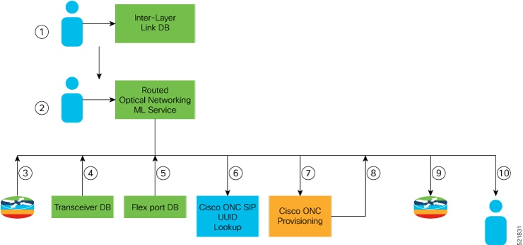
Add the Cisco Optical Network Controller instance as a device in NSO to support end-to-end multi-layer provisioning. For more information, see the Cisco NSO Routed Optical Networking Core Function Pack User Guide.
 Feedback