Provision Control Cards

This chapter describes the control cards used in Cisco NCS 2000 SVO and its related tasks.

The following table lists the package support for the control cards.

Card

SSON Package

(12.xx-xxxx-xx.xx-S-SPA)

MSTP Package

(12.xx-xxxx-xx.xx-L-SPA)

SVO

TSCE

TNC

TNCE

TNCS

TNCS-O

TNCS-2

TNCS-2O

SVO Card

In this chapter, "SVO" refers to the NCS2K-SVO-K9 card.

The Shelf Virtualization Orchestrator (SVO) card is a two-slot card, which allows better management and control of multichassis solutions for the Cisco NCS 2000.

SVO extends the Network Services Orchestrator (NSO) application by network topology-aware virtualization, thereby improving the management of Cisco NCS 2000 through alarms, status and connection verifications, and so on.

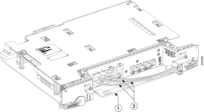
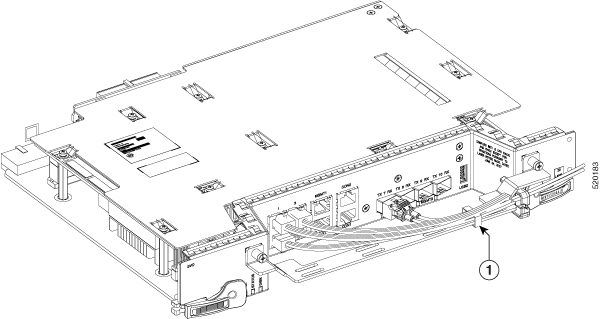
SVO card enables High Availability functionality by connecting the two SFP+ 10GE optics back-to-back with another SVO card

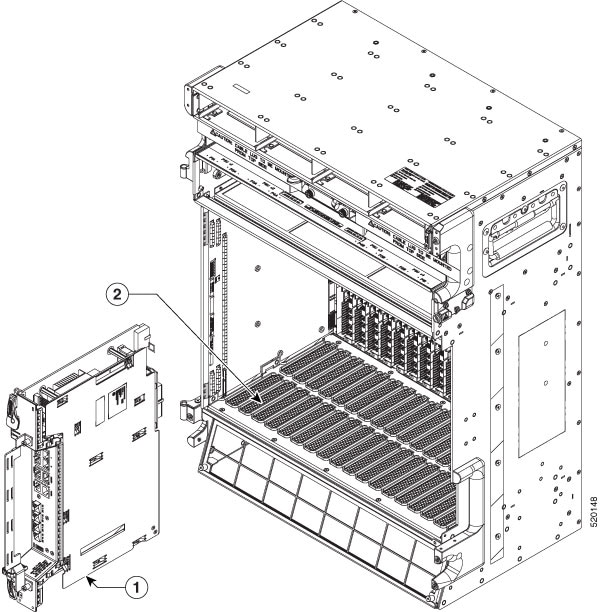
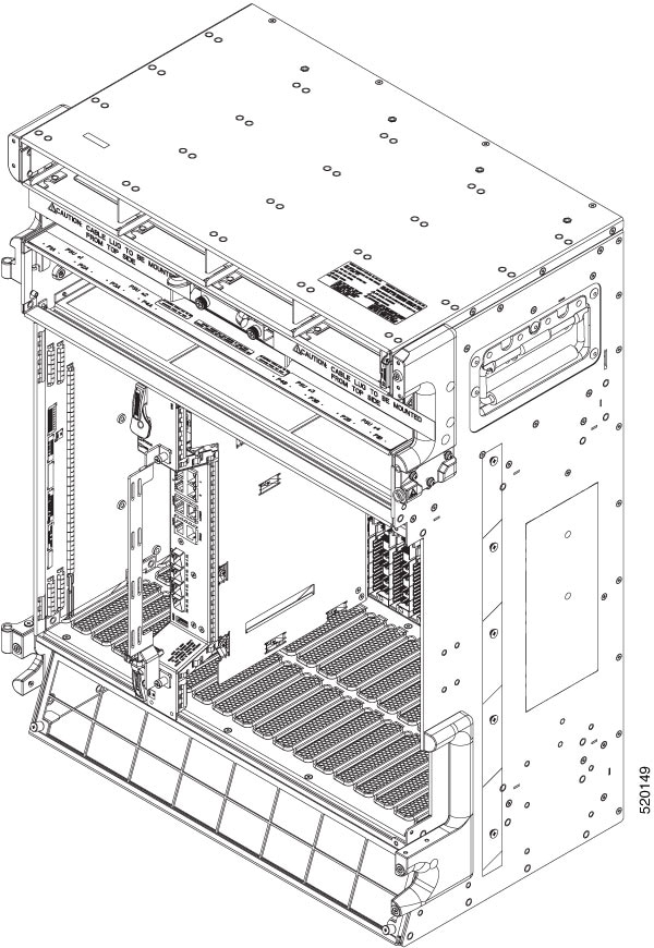
The SVO card is provisioned as active and standby in the Cisco NCS 2006 or Cisco NCS 2015 chassis.

SVO card has a powerful 12 core 2GHz Intel Xeon processor with 64GB DDR4 RAM, 240GB SSD, 4x SFP+ ports, 5x 1GE copper for External Switch, 2x USB 3.0 along with Ethernet management and Console port.

On the Cisco NCS 2015 shelf, the cards can be installed in slots 2 to 15.

On the Cisco NCS 2006 shelf, the cards can be installed in slots 2 to 6.

The following pluggables on the four front panel ports.

SFP+ (10G)

SFP (1G)

ONS-SC+-10G-SR=

ONS-SI-GE-SX=

ONS-SC+-10G-LR=

ONS-SI-GE-LX=

SFP-10G-SR=

ONS-SE-ZE-EL=

SFP-10G-LR=

The card has the features:

  • Introduces a NETCONF interface with Cisco YANG models and a Nodal Craft web application.

  • Hosts up to 15 OLA, DGE, or TXP container along with one ROADM in Release 12.3 and earlier.

  • Hosts up to 20 OLA, DGE, or TXP container along with one ROADM in Release 12.3.1.

  • Runs in complete redundancy mode with another standby SVO card.

  • Provides selfmonitored hardware status with on board logging.

  • Provides virtualization of nodes in a network.

TNC and TNCE Card

Cisco NCS 2002 and Cisco NCS 2006

On the NCS 2006 shelf, install redundant TNC or TNCE cards in slots 1 and 8. If the active TNC or TNCE card fails, the system traffic switches to the redundant TNC or TNCE card.

The NCS 2006 shelf has dual power supply. The TNC or the TNCE card monitors both supply voltage inputs on the NCS 2006 shelf. The TNC or TNCE card raises an alarm if one of the supply voltage inputs has a voltage out of the specified range.

You can insert and remove the TNC or TNCE card without impacting the system traffic, even when the system is online.


Note


The TNC and TNCE cards are not supported on NCS 2015. When these cards are inserted into the active or standby slots of the NCS 2015 chassis, the cards do not start and become active.


TSCE Card

Cisco NCS 2002 and Cisco NCS 2006

The TSCE card is provisioned as active and standby in the NCS 2006 shelf. The TSCE card serves as the processor card for the shelf.

The NCS 2006 shelf has dual power supply. The TSCE card monitors both supply voltage inputs on the NCS 2006 shelf. The TSCE card raises an alarm if one of the supply voltage inputs has a voltage out of the specified range.

You can insert and remove the TSCE card without impacting the system traffic, even when the system is online.

The TSCE card does not support optical service channel (OSC) and SFP ports.


Note


The TNC, TNCE, and TSCE cards cannot be inserted in the same shelf.

The TSCE card is not supported on NCS 2015. When the card is inserted into the active or standby slots of the NCS 2015 chassis, the card does not start and become active.


TNCS Card

In this chapter, "TNCS" refers to the NCS2K-TNCS-K9 card.

The TNCS cards are provisioned as active and standby in the Cisco NCS 2006 or NCS 2015 shelves. On the NCS 2015 shelf, the TNCS cards can be installed in slots 1 and 17. On the NCS 2006 shelf, the cards can be installed in slots 1 and 8. If the active TNCS card fails, the system switches to the redundant TNCS card.

The NCS 2015 shelf is powered by DC power modules with 3+1, 2+2, 2+1, or 1+1 redundancy. A minimum of one power module is required to turn up the chassis. The number of power modules to be connected is dependent on the chassis load. The TNCS cards raise an alarm if one of the supply voltage inputs has a voltage out of the specified range.

You can insert and remove the TNCS cards without impacting the system traffic, even when the system is online.

TNCS-O Card

In this chapter, "TNCS-O" refers to the NCS2K-TNCS-O-K9 card.

The TNCS-O card is provisioned as active and standby in the Cisco NCS 2006 or NCS 2015 shelves. On the NCS 2015 shelf, the TNCS-O card can be installed in slots 1 and 17. On the NCS 2006 shelf, the card can be installed in slots 1 and 8. If the active TNCS-O card fails, the system switches to the redundant TNCS-O card.

The TNCS-O cards support only Fast Ethernet (FE) and wavelength of 1518 nm in OSC transmissions.


Note


OC-3 and ONE-GE payloads are not supported by the TNCS-O card.
The OSC transmission ranges are:
  • Standard range: 12 - 43 dB

  • Reduced range: 5 - 30 dB


Note


The OTDR feature of TNCS-O and TNCS-2O cards is not supported over DWDM network configuration having PSM card at the line side of booster amplifier. In this configuration, the PSM Working (W) and Protect (P) ports are connected to the fiber. The OTDR signal is split into both W and P fibers and back reflected light from both the fibers leads to inconsistent OTDR results.


TNCS-2 and TNCS-2O Cards

In this chapter, "TNCS-2" refers to the NCS2K-TNCS-2-K9 card. "TNCS-2O" refers to the NCS2K-TNCS-2O-K9 card.

(NCS 2002, NCS 2006, NCS 2015)

The TNCS-2 and TNCS-2O cards are provisioned as active standby in the NCS 2006 or NCS 2015 chassis.

On the NCS 2015 shelf, the TNCS-2 and TNCS-2O cards can be installed in slots 1 and 17.

On the NCS 2006 shelf, the cards can be installed in slots 1 and 8.

On the NCS 2002 shelf, the cards can be installed in slot 1.

You can insert and remove the TNCS-2 and TNCS-2O cards without affecting the system traffic, even when the system is online.

The card has the following features:

  • The TNCS-2 and the TNCS-2O cards work in redundant mode with another TNCS-2, TNCS-2O, TNCS, TNCSO, or TNCE cards.

  • Synchronous Ethernet is supported on all GE and FE ports of the TNCS-2 and the TNCS-2O cards.

  • The TNCS-2 and TNCS-2O cards address CPU EOL and SDRAM supply issues on the existing controller cards.

  • The TNCS-2 and the TNCS-2O cards supports a secure boot.

  • The TNCS-2 and TNCS-2O cards exhibit chassis control functions including the control of power supplies, fans, ECU, optical modules, clock synchronization, and line card configuration. It can also configure the field programmable devices present in the TNCS-2 or TNCS-2O card.

  • The TNCS-2 and TNCS-2O cards support environment monitoring and alarm reporting features.


  • Note


    The TNCS-2 and TNCS-2O cards cannot be installed in the chassis that runs software earlier than R11.0.


  • All packages are supported on the TNCS-2 and TNCS-2O cards.

The Lamp Test button is not available on the TNCS-2 and TNCS-2O cards.


Note


When the EMS port is configured with 10 Mbps speed for TNCS-2 and TNCS-2O cards, it causes unicast storm control over the EMS peer port connected to the switch. However, when the storm controller is enabled on the EMS port for unicast packets on the switch, the EMS link goes down.


Table 1. The TNCS-2 and TNCS-2O cards support the following shelf control options:

Standby Slot

Active Slot

Support

TSC

TNCS-2O

Not Supported

TSC-E

TNCS-2O

Not Supported

TNC

TNCS-2O

Not Supported

TNC-E

TNCS-2O

Yes

TNCS

TNCS-2O

Yes

TNCS-O

TNCS-2O

Yes

TNCS-2

TNCS-2O

Yes

TSC

TNCS-2

Not Supported

TSC-E

TNCS-2

Not Supported

TNC

TNCS-2

Not Supported

TNC-E

TNCS-2

Yes

TNCS

TNCS-2

Yes

TNCS-O

TNCS-2

Yes

TNCS-2O

TNCS-2

Yes

Power Settings of TNCS-O and TNCS-2O OTDR Ports

OTDR ports of TNCS-O and TNCS-2O operate in two modes:

  • High Power

  • Low Power

These power changes occur based on the settings of the Max Expected Span Loss parameter. If the Max Expected Span Loss parameter is set to 28 dB or less, OTDR ports operate in low power and if the Max Expected Span Loss parameter is set to more then 28 dB, OTDR ports operate in high power.

After changing the value of Max Expected Span Loss parameter, you must perform Launch ANS from CTC as it is an ANS parameter.

Installing the TNC, TNCE, TSCE, TNCS-2, TNCS-2O, TNCS-O, or TNCS Card

This task installs active and standby cards on the Cisco NCS 2006 or Cisco NCS 2015 shelf.


Caution


Do not remove the control cards during the software installation process, which is indicated by the alternate flashing of the FAIL and ACT/STBY LEDs. Removing the control cards during the software installation process corrupts the system memory.


Note


Allow each control card to boot completely before installing the redundant control card.


Note


TNCS and TNCS-O cards are having new bootcode version from R12.2. Due to this, TNCS and TNCS-O cards go for an additional reboot during software upgrade to R12.2.


Note


You cannot insert the control cards in other slots due to mechanical constraints. To identify the card slot, match the symbol placed on the lower side of the card front panel with the symbol on the shelf.


Procedure


Step 1

Open the latches or ejectors of the first control card that you will install.

Step 2

Use the latches or ejectors to firmly slide the card horizontally along the guide rails until the card plugs into the receptacle at the back of the slot (slot 1 or 8 in the NCS 2006 shelf, slot 1 or 17 in the NCS 2015 shelf).

Note


The cards slide vertically in the NCS 2015 shelf.

Step 3

Verify that the card is inserted correctly, and close the latches or ejectors on the card.

If you insert a card into a slot assigned for a different card, all LEDs turn off.

Step 4

If needed, verify the LED activity on the control card.

  • The red FAIL LED, PWR LED turn on briefly.

  • The red FAIL LED turns on for about 10 seconds.

  • The red FAIL LED and the amber ACT/STBY LED turn on for about 30 seconds.

  • The red FAIL LED blinks for about 10 seconds.

  • The red FAIL LED turns on for about 15 seconds.

  • All the LEDs including the CRIT, MAJ, MIN, REM, SYNC, and ACO LEDs blink once and turn off for about 10 seconds.

  • ACT/STBY LED blinks for about 1 second.

  • All the LEDs including the CRIT, MAJ, MIN, REM, SYNC, and ACO LEDs turn off for about 10 seconds.

  • The ACT/STBY, ACO, and PWR LEDs turn on.

  • The boot process is complete when the PWR LEDs turn green and the amber ACT/STBY LED remains on. The ACT/STBY LED turns green if this is the first control card installed, but turns amber if this is the second control card installed.

    Note


    It might take up to four minutes for the power alarms to clear.

    Note


    During the control card initialization, the SFTWDOWN alarm appears twice. The alarm clears after the control card boots completely.

    Note


    If the FAIL LED is on continuously, see the note in Step 8 about the control card automatic upload.

Figure 1. Installing TNC and TNCE Cards on the NCS 2006 Shelf
Figure 2. Installing TNCS/TNCS-O Cards on the NCS 2015 Shelf


1

TNCS/TNCS-O Card

2

Guide Rail

Step 5

Verify that the ACT/STBY LED is green if this is the first powered-up control card installed or amber if this is the second powered-up control card. The IP address, temperature of the node, and time of day appear on the LCD. The default time and date is 12:00 AM, January 1, 1970.

Step 6

The LCD cycles through the IP address (the default is 192.1.0.2), node name, and software version. Verify that the correct software version is shown on the LCD. The software text string indicates the node type (SDH or SONET) and software release. (For example: SDH 09.20-05L-20.10 indicates it is an SDH software load, Release 9.2. The numbers following the release number do not have any significance.)

Step 7

If the LCD shows the correct software version, continue with Step 8. If the LCD does not show the correct software version, refer to your next level of technical support, upgrade the software, or remove the control card and install a replacement card. Refer to the release-specific software upgrade document to replace the software.

Step 8

(NCS 2006 or NCS 2015 shelf only) Repeat Steps 1 through 7 for the redundant control card.

Note

 
If you install a standby control card that has a different software version than the active control card, the standby control card copies the software version from the one in the active control card. When the standby card is first inserted, the LEDs follow the normal boot-up sequence. However, after the red FAIL LED turns on for about 5 seconds, the FAIL LED and the ACT/STBY LED begin to flash alternately for up to 30 minutes. After loading the new software, the upgraded control cards LEDs repeat the appropriate bootup sequence, and the amber ACT/STBY LED turns on.

Step 9

Return to your originating procedure.


Installing the SVO Card

This task installs the SVO card on the Cisco NCS 2006 or the Cisco NCS 2015 shelf.


Note


Install and configure the SVO card before installing any other line cards into the shelf assemblies.

When you install the SVO card on the NCS 2000 chassis, the PWR-CON-LMT alarm is raised when the power consumption limit is exceeded. We recommend that you remove the SVO card and place it in another chassis that supports the required power.


Procedure


Step 1

Align the SVO card so the markings on the card and the chassis are on the same side.

Step 2

Open the latches or ejectors of the first SVO card that you will install.

Step 3

Use the latches or ejectors to firmly slide the card horizontally along the guide rails until the card plugs into the receptacle at the back of the slot (any slot from slot 2 to 6 in the NCS 2006 shelf or slot 2 to 15 in the NCS 2015 shelf).

Step 4

Verify that the card is inserted correctly, and close the latches or ejectors on the card.

Figure 3. Installing SVO Card on the NCS 2015 Shelf

1

SVO Card

2

Guide Rail

Figure 4. Installed SVO Card on the NCS 2015 Shelf
Figure 5. Installing SVO Card on the NCS 2006 Shelf

1

SVO Card

2

Guide Rail

Figure 6. Installed SVO Card on the NCS 2006 Shelf

Cable Routing for SVO Card

This task routes the cables on the SVO card that you are installing on the Cisco NCS 2006 or Cisco NCS 2015 shelf.

Before you begin

Procedure


Step 1

Route the optical fiber cables under the cable management bracket through the optical fiber clip as shown below.

1

Cable Management Bracket

2

Optical Fiber Cables

3

Clip for Optical Fibers

Step 2

Route the Amphenol, CAT6 FTP flat cable or an equivalent on top of the cable management bracket.

1

Cable Management Bracket

2

CAT6, FTP flat cable.

For 1G copper ports use Amphenol CAT6, FTP flat cables (CMP compatible) or Equivalent.

Note


The CMP compliant flat cable manufacturer is Amphenol and the MPN's for the same are 1 meter, 3 meters, and 10 meters.

Step 3

Wrap the velcro tape over the cable management bracket to retain the cables in position.

1

Velcro tape over the cable management bracket to retain the cables in position.


Provision PPM

Use this task to provision the Pluggable Port Module (PPM) on the control card.

Before you begin

Procedure


Step 1

Click the Provisioning > Pluggable Port Modules tabs.

Step 2

Click the + button.

The Add PPM dialog box appears.

Step 3

Choose the PPM port from the PPM drop-down list and click Apply.

The newly created PPM appears in the Pluggable Port Modules tab.


Provision Operating Mode

Use this task to provision the operating mode on the control card.

Before you begin

Procedure


Step 1

Click the Provisioning > Card Mode tabs.

Step 2

In the Card Mode area, choose TNC-MODE or TNCO-MODE and click Apply.

The control cards can be configured either in TNC or TNCO operating mode. The TNC mode is the default operating mode for the cards. A card is configured in TNCO mode if the actual card that must be inserted into a shelf is a TNCS-O card.


Provision UDC

Use this task to provision the UDC on the control card.

Before you begin

Procedure


Step 1

Click the Provisioning > UDC tabs.

The UDC tab displays the port and its service type. Only the service type port can be manually changed.

Step 2

Click on the Service Type cell for the port you wish to change the service type.

A drop-down list appears with options NONE and UDC.

Step 3

Choose the Service Type mode from the drop-down list.

Step 4

Click Apply.


Provision RMON Thresholds

Use this task to provision the RMON thresholds on the control card.

Before you begin

Procedure


Step 1

Click the Provisioning > RMON Thresholds tabs.

Step 2

Click the + button.

The Create RMON Threshold dialog box appears.

Step 3

From the Port ID drop-down list, choose the port number.

Step 4

From the Variable drop-down list, choose a variable.

Step 5

From the Alarm Type drop-down list, indicate whether the event is triggered by the rising threshold, falling threshold, or both thresholds.

The available options are Rising Threshold, Falling Threshold, and Rising and Falling Threshold.

Step 6

From the Sampling Type drop-down list, choose either Relative or Absolute.

Relative restricts the threshold to use the number of occurrences within the user-set sample period.

Absolute sets the threshold to use the total number of occurrences, regardless of the time period.

Step 7

Enter the appropriate number of seconds in the Sampling Period field.

Step 8

Enter the appropriate number of occurrences in the Rising Threshold field.

For a rising type of alarm, the measured value must move from below the falling threshold to above the rising threshold. For example, if a network is running below a rising threshold of 1000 collisions every 15 seconds and a problem causes 1001 collisions in 15 seconds, the excess occurrences trigger an alarm.

Step 9

Enter the appropriate number of occurrences in the Falling Threshold field.

In most cases, a falling threshold is set lower than the rising threshold.

Step 10

Click Apply.


Change Admin State for SVO Card Ports

Use this task to change the admin state of the ports on the SVO card.

Before you begin

Procedure


Step 1

Click the Provisioning tab.

The different ports along with their rates, reach distances, and admin states are displayed in the Ports pane.

Only the admin state of each port may be changed. For ANSI node, the admin state options are IS, OOS, and AINS. For ETSI nodes, the admin state options are unlocked, locked, or maintenance.

Step 2

Change the admin state as appropriate and click Apply.

Step 3

(Optional) Choose a port from the drop-down list and click Reset to Defaults to reset the port to default values.


Provision Optical Threshold Settings for the SVO Card

Use this task to provision the optical thresholds on the SVO card.

Before you begin

Procedure


Step 1

Click the Provisioning > Optics Thresholds tabs.

Step 2

Choose the type of threshold that you want to change, 15 Min TCA, 1 Day TCA, or Alarm.

Step 3

Click Refresh to view the latest values.

Step 4

Modify any of the following threshold settings as needed by double-clicking the threshold value, deleting it, and entering a new value.

  • Port—(Display only) Displays the port number and port type.

  • Laser Bias High—Sets the maximum laser bias in percentage.

  • RX Power High—Sets the maximum optical power received in dBm.

  • RX Power Low—Sets the minimum optical power received in dBm.

  • TX Power High—Sets the maximum optical power transmitted in dBm.

  • TX Power Low—Sets the minimum optical power transmitted in dBm.

Step 5

Click Apply.

Step 6

Click Yes to complete the changes.


Backup the System Database

From R12.01 onwards, you can back up the database of SVO instance and NCS 2000 on the SVO card. You can backup the database on an individual node on which the SVO node-level software is running. The SVO instances of SVO node-level database include ROADM nodes, and NCS 2000 nodes connected to ROADMs.

You can request the backup using the NETCONF command (RPC call). For example, you can use the following XML for backup.


backup='''
<action xmlns="http://tail-f.com/ns/netconf/actions/1.0">
<data>
<svo-backup xmlns="http://cisco.com/yang/svo/diag">
<commands>
<backup>
</backup>
</commands>
</svo-backup>
</data>
</action>

The backup is performed and the database is stored on the SVO. You can view the backups taken from the SVO web UI. You can take any number of backups as required but the last backup taken is only available to download.

View the System Database Backup

Use this task to view the backup taken for the system database.

Procedure


Step 1

Click the hamburger icon at the top-left of the page, and Select Database.

In the Database page, you can view the following information:

  • Latest Backup File Name

  • Latest Backup Timestamp

  • Current Status

  • Log Message

  • Current Log Status Timestamp

Step 2

Click Download to download the current backup.

The current backup is downloaded to your system.

Step 3

In the Database page, you can view a list of backups taken with the following information for the ROADM and NCS 2000 nodes:

  • Component—Displays the list of ROADM and NCS 2000 node names.

  • Log message—Displays whether the backup for the component is performed or not.

  • Timestamp—Displays the date and time at which the backup is taken.


Restore the System Database from a Backup

You can back up the database of SVO instance and NCS 2000 on the SVO card. You can back up the database on an individual node on which the SVO node-level software is running. The SVO instances of SVO node-level database include NCS 2000 nodes.

The following steps describe how to perform the database restore operation.

  1. Click the hamburger icon at the top-left of the page, and Select Database.

    In the Database page, you can view a list of backups that are taken for the ROADM and NCS 2000 nodes.

  2. (Optional) Click Upload to upload a backup file.

    The backup file that you upload is the latest backup file.

  3. Click Restore to restore the SVO node to the latest backup file.

    The restore process takes some time to complete. After the restore process, you have to log in to the SVO container again.


Note


When you create a new container and restore the database:

  • If the SVO instance name and Device name are the same as in the backup file, but the SVO instance IP address is different, database restore operation takes place.

  • If the SVO instance name is different from the one in the backup file, database restore operation fails with the following error message.

    Request cannot be executed: Backup file was generated in SVO 'old-name' but current SVO is 'new-name' 
  • If the Device name is different from the one in the backup file, database restore operation fails with the following error message.

    DB Restore of all devices completed with some error.
    SVO_NAME (SVO) restore-procedure of component is busy saving recent modifications. Please retry this operation later.	
    DEVICE_NAME (NCS2K)	restore-procedure of component is failed.
  • If the backed-up database contains both SVO and NCS2K components, add the NCS2K component to the SVO container before restoring. Otherwise, database restore operation fails with the following error message.

    Request cannot be executed: Backup file was generated with '1' device(s) but currently '0' present(s)