Remove and Replace Cisco NCS 1010 Modules

This chapter describes the tasks to remove and replace Cisco NCS 1010 modules.


Caution


Always populate the modular slots in the Cisco NCS 1010 chassis with respective modules (line card, controller, PSU, and fan trays). Perform the replacement or upgrade of the modules (Online Insertion or Removal (OIR)) only when the ambient temperature is below 30-degree Celsius. Complete the OIR of modules within five minutes to prevent overheating of the components.


Warning


Statement 1028—More Than One Power Supply

This unit might have more than one power supply connection. To reduce risk of electric shock, remove all connections to de-energize the unit.


Warning


Statement 1073—No User-Serviceable Parts

There are no serviceable parts inside. To avoid risk of electric shock, do not open.


Warning


Statement 1089—Instructed and Skilled Person Definitions

An instructed person is someone who has been instructed and trained by a skilled person and takes the necessary precautions when working with equipment.

A skilled person or qualified personnel is someone who has training or experience in the equipment technology and understands potential hazards when working with equipment.

There are no serviceable parts inside. To avoid risk of electric shock, do not open.


Warning


Statement 1090—Installation by Skilled Person

Only a skilled person should be allowed to install, replace, or service this equipment. See statement 1089 for the definition of a skilled person.

There are no serviceable parts inside. To avoid risk of electric shock, do not open.


Warning


Statement 1091—Installation by an Instructed Person

Only an instructed person or skilled person should be allowed to install, replace, or service this equipment. See statement 1089 for the definition of an instructed or skilled person.

There are no serviceable parts inside. To avoid risk of electric shock, do not open.


Note


The maximum operating altitude for OIR is 1800 m.


Remove and Replace Controller

Use this task to remove and replace the controller in the Cisco NCS 1010 chassis.

Procedure


Step 1

Using a screwdriver, unfasten the two captive screws on the controller.

Step 2

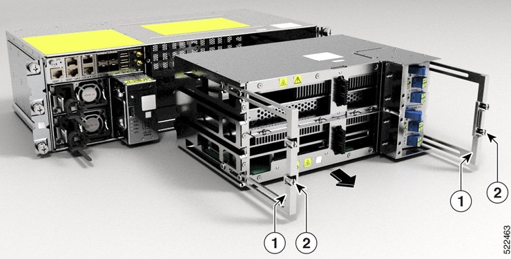
Pull out the handle from the controller

Step 3

Holding the handle with one hand and supporting the controller with the other, gently remove the controller from the slot.
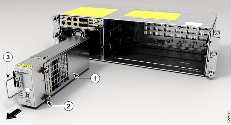
Figure 1. Removing the Controller

1

Controller

2

Captive screws

3

Handle


What to do next

To replace the controller, see Install Controller.

Remove and Replace PSU

Use this task to remove and replace a PSU in the Cisco NCS 1010 chassis.

Before you begin

Remove the connections to the PSU:

  • Disconnect power from the breaker before disconnecting power from the PSU.

  • Remove the cable from the retainer and the PSU, in case of an AC PSU installation.

  • Disengage the latch available in the DC Cable connector from the DC PSU to remove the cable.

Procedure


Step 1

Press the locking latch towards the right to release the lock.

Figure 2. Locking Latch of AC Power Supply
Figure 3. Locking Latch of DC Power Supply

1

Latch

Figure 4. Removing the PSU

Step 2

Supporting the PSU with the one hand, gently pull out the PSU from the slot.


What to do next

To replace the PSU, see Install PSU.

Remove and Replace Fan Filter

The fan filter removes dust from the fan that is drawn into the chassis by the fan trays. If the fan filters are damaged, dirty, or clogged with dust, they must be replaced with a new fan filter. Failure to replace a compromised fan filter can result in insufficient fan circulation through the chassis and temperature-related environmental alarms.

Use this task to remove and replace the fan filter.


Note


First inspection of the fan filter must be performed six months after the first installation of the fan filter. Air filters must be inspected every three months after the initial six-month inspection and replaced if found to be dirty. Cleaned fan filters cannot be reused. Replace with a new fan filter. We recommend having spare fan filters in stock.


Procedure


Step 1

Loosen the four captive screws in the fan filter from the standoffs in the fan trays.

Figure 5. Removing the Fan Filter

1

Fan filter

2

Captive Screw

Step 2

Gently remove the fan filter from the fan tray.


What to do next

To replace the fan filter, see Install Fan Filter.

Remove and Replace Fan Tray

Use this task to remove and replace a fan tray in the Cisco NCS 1010 chassis.


Caution


Online Insertion and Removal (OIR) duration for the fan tray unit at 30 degree Celsius ambient temperature, is five minutes.

Only one fan tray should be removed at a time. Removing both fan trays simultaneously leads to overheating and may result in an unexpected system shutdown.


Before you begin

Remove the fan filter.

Procedure


Step 1

Loosen the captive screws (one on the left side and other on the right side) using a screwdriver.

Step 2

Using the handle pull the fan tray out of the chassis.

Figure 6. Removing the Fan Tray

1

Fan

2

Captive Screw

Step 3

Repeat Step 1 and Step 2 to remove the second fan tray.


What to do next

To replace the fan tray, see Install Fan Tray.

Remove and Replace Line Card

Use this task to remove and replace the line card in the Cisco NCS 1010 chassis.

Before you begin


Caution


  • Perform the removal and replacement procedure for the line card only when the ambient temperature is below 30 degree Celsius and complete it within five minutes to prevent overheating of the chassis components.

  • Ensure that you perform the removal and replacement of the fan filter, fan trays, protection cover, and line card within the five minutes of time limit.

  • As the fan trays draw power through the line card, you must complete the line card replacement before installing the fan trays on top of it.


Procedure


Step 1

Loosen the captive screws available in the line card handles.

Step 2

Pull the handles out of the line card, and gently remove the card from the chassis.

Caution


Use the handles only to push and pull out the line card from the chassis. Do not use the handles to carry the line card. To prevent any accidental drop, support the top and bottom of the line card with your hand while you remove or insert it.

Figure 7. Removing the Line Card

1

Handle

2

Captive Screws


What to do next

To replace the line card, see Install Line Card.

Wipe Data in Disk Using Secure Erase

When NCS 1010 becomes faulty, contact TAC to open a Return Material Authorization (RMA) request. Before opening an RMA request, you can securely erase data on NCS 1010 disks using the Secure Erase feature.


Warning


Use this procedure only during RMA.


Before you begin

  • The NCS 1010 unit that is planned for RMA must be taken out of the data center and the network. You must access NCS 1010 only using the console port.

  • You must perform the RP cold reload for the successful CPU disk wipe.

  • You must perform the chassis cold reload for the successful Chassis disk wipe.

Procedure


Step 1

When NCS 1010 boots during RP cold reload or chassis cold reload, the following message appears.


Version 2.19.1266. Copyright (C) 2022 American Megatrends, Inc.
BIOS Date: 06/22/2022 08:29:52 Ver: 0ACHI0420
Press <DEL> or <ESC> to enter setup.
Press DEL or ESC key to enter BIOS.

Press DEL or ESC key to enter BIOS.

Step 2

Select the Advanced tab using the arrow keys.

The disk security details such as HDD Secure Erase are displayed in the Advanced tab.

Step 3

Select HDD Secure Erase to securely erase data.

Step 4

Select the SSD using the arrow keys.

  1. Select the SSD under D: 13 for RP cold reload.

  2. Select the SSD under D: 14 for chassis cold reload.

Step 5

Click Yes on the Warning message box to erase the selected SSD data.


Upgrade an NCS 1010 EDFA only Network to a Raman Network

The following topics describe how to upgrade an NCS 1010 EDFA only network to a Raman network.

Prerequisites

  • Maintain the same physical connections as the EDFA only NCS 1010 nodes.

  • You need E2000-LC patch cords for the NCS 1010 Raman ports on the NCS 1010 MPO faceplate. Make sure you have E2000-LC patch cords for each MPO faceplate Raman port. For LC faceplate OLTs, use LC-LC patch cords.

  • Raman amplification is sensitive to reflection and loss. Make sure you have the necessary cleaners and fiber scope for any troubleshooting.

Copy Configuration

On each existing EDFA device on the network, perform the following steps:

  1. Use the show running-config command to get the controller configuration.

  2. Copy the configuration to a file on your local system and save the file.


Note


This configurations include all the cross-connect configuration on OLTs. Copying these configurations to the Raman module ensures that you do not need to recreate the cross-connect configuration on the Raman node.


Replace the Hardware

You have the following two options to replace the hardware.

  • Replace the whole chassis with a Raman OLT or ILA chassis.

  • Replace the OLT or ILA line card with a corresponding Raman line card.

Replace all OLT and ILA nodes with corresponding Raman nodes.

1: Replace the Entire NCS 1010 Chassis

For instructions to assemble the NCS 1010 chassis, see Install Cisco NCS 1010 Modules.

  1. Remove the existing fiber connections from the NCS 1010 chassis.

  2. Loosen the screws of the NCS 1010 chassis in the rack or adapter brackets.

  3. Support the top and bottom of the NCS 1010 chassis with your hand to extract the chassis.

  4. Install the Raman ILA or OLT module by following the instructions at Install Cisco NCS 1010.

  5. Make the fiber connections maintaining the previous connections.

2: Replace the Line Card Only

Prerequisites:

  1. Remove the existing fiber connections from the NCS 1010 chassis.

  2. Remove the OLT or ILA line card by following the instructions at Remove and Replace Line Card.

  3. Install the Raman line card. For steps to install the line card, see Install Line Card.

  4. Make the fiber connections maintaining the previous connections.

Apply Configuration to Raman Nodes

Boot up the new nodes. For instructions to boot, see Boot NCS 1010.

Apply the configurations copied in Copy Configuration to the newly installed Raman nodes.

Initial Setup of Raman Nodes

Initiate Raman tuning and gain estimation so that Automatic Power Control gets the necessary setpoints. Link tuner runs automatically when it detects changes in the network and during network bring-up.

For more information on Raman Tuning, Gain Estimation, Link Tuner, and APC, see the following links:

Use the following commands to initiate these operations.

  • olc start-raman-tuning controller ots Rack/Slot/Instance/Port

  • olc start-gain-estimation controller ots Rack/Slot/Instance/Port


Note


Raman tuning blocks gain estimation from executing while tuning is in progress. Wait until Raman tuning status changes to Tuned before initiating gain estimation.


The circuits on the new Raman nodes should be up if the configurations were copied and port connections were mapped accurately between the EDFA implementation and Raman implementation.