Install Cisco NCS 1010 Modules

This chapter describes the tasks to install Cisco NCS 1010 modules.


Caution


Always populate the modular slots in the Cisco NCS 1010 chassis with respective modules (line card, controller, PSU, and fan trays). Perform the replacement or upgrade of the modules (Online Insertion or Removal ( OIR)) only when the ambient temperature is below 30 degree Celsius. Complete the OIR of modules within five minutes to prevent overheating of the components.


Install PSU

Use this task to install PSU into the Cisco NCS 1010 chassis. You can install two AC PSUs or two DC PSUs in a chassis.

Procedure


Step 1

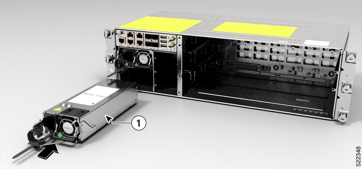
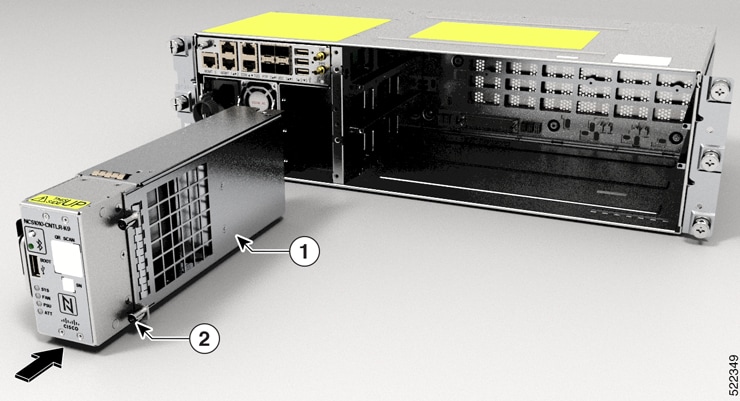
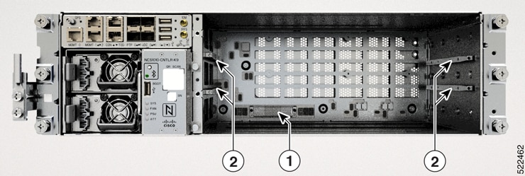
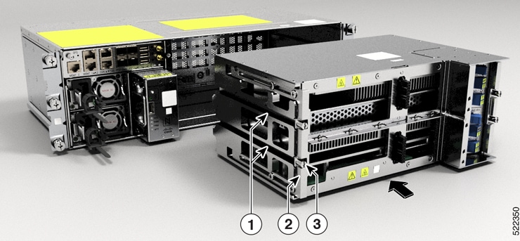
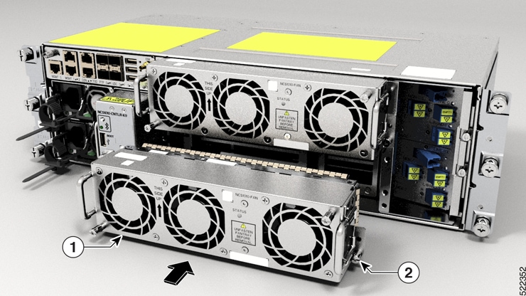
Orient the PSU correctly before inserting.
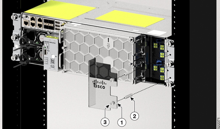
Step 2

Using the handle, slide the PSU into the slot (support the PSU at the bottom with your hand) and push it in until you hear a click sound; direction of insertion is shown in the following figure. The click sound indicates that the unit has been latched. .

Note


The locking latch must be pressed and released only for removing the PSU.

Figure 1. Installing the PSU

1

PSU unit


Connect AC Power to Cisco NCS 1010


Caution


Cisco NCS 1010 relies on the protective devices in the building installation to protect against short circuit, overcurrent, and ground faults. Ensure that the protective devices comply with local and national electrical codes.


Figure 2. Rating Label for AC Power

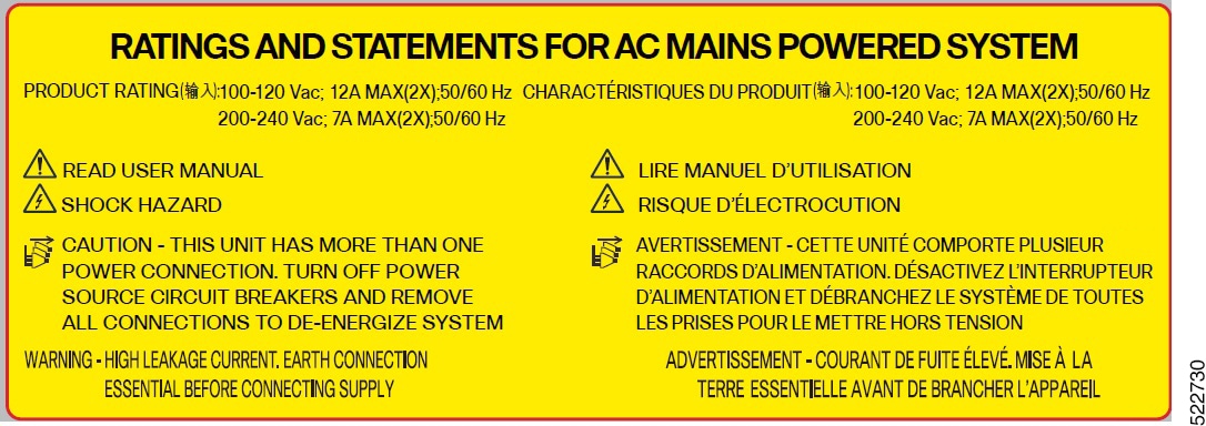
AC power ratings: The voltage rating value for AC power ranges either 200–240 or 100–127 V depending on the standards in various countries.

  • Input: 100-120Vac, 12A, 50-60HzDC

    Outputs: +12V, 67A Max. +12Vsb, 3A Max. Total output power 800W.

  • Input: 200-240Vac, 7A, 50-60HzDC

    Outputs: +12V, 87.5A Max. +12Vsb, 3A Max. Total output power 1050W.


Note


A dual pole breaker is needed for the installation. The rating of the dual pole breaker for each feed is 16A for input voltage 200–240 Vac, and 20A for input voltage 100–127 Vac.


Procedure


Step 1

Verify that the AC cable is installed in the correct AC source panel. Ensure that either the fuse is removed or the circuit breaker is in the off position and locked out.

Step 2

Attach the AC power cable to the cable connector in the AC power module. See Power Cable Specifications for the supported AC power cables.
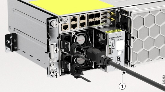
Figure 3. Connecting AC Power Cable

1

AC power cable

Step 3

Close the cable retention clips to secure the power cables and to prevent their accidental removal.


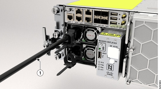
Connect DC Power to Cisco NCS 1010


Caution


Cisco NCS 1010 relies on the protective devices in the building installation to protect against short circuit, overcurrent, and ground faults. Ensure that the protective devices comply with local and National Electrical Codes.
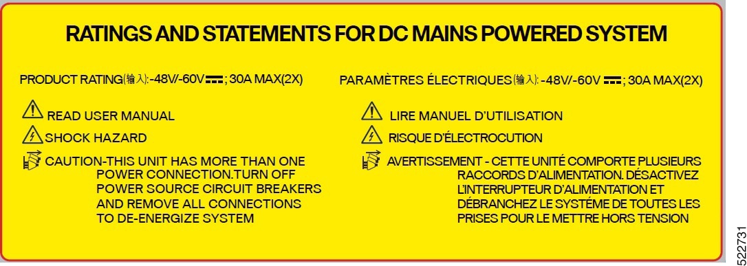

Figure 4. Rating Label for DC Power

DC power ratings:

  • Input: 48-60Vdc, 30A.

  • DC output: +12V, 87.5A Max. +12Vsb, 3A Max. Total output power must not exceed 1050W.

Before you begin

  1. In the installation of the chassis, the ground lug must be connected first.

  2. The ground lug must be attached before energizing the chassis.

Procedure


Step 1

Verify that the correct fuse panel is installed in the top mounting space.

Step 2

Measure and cut the cables as required to reach Cisco NCS 1010 from the fuse panel.

Step 3

Connect the office battery and return cables according to the fuse panel engineering specifications.
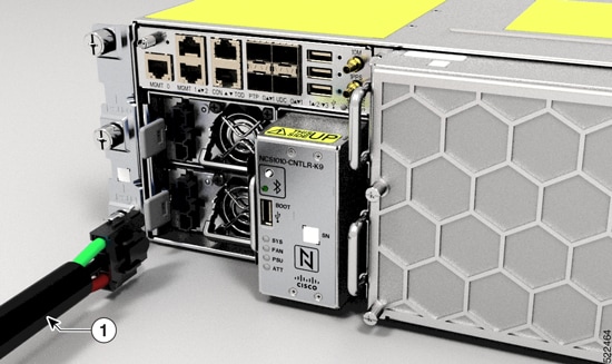
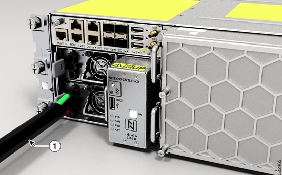
Step 4

Attach the DC power cable to the cable connector in the DC power module.

Use the CAB-48DC-40A-8AWG or NCS1010-DC-CBL-ET= cable. We recommend using NCS1010-DC-CBL-ET= with the ETSI 300-mm cabinet to remain compliant with the 300-mm footprint. See Power Cable Specifications.

Note


Ensure to ground the green colored cable.

The green-colored cable is provided as an optional connection to the GND terminal on the fuse panel that has a dedicated GND terminal.

Figure 5. Connecting DC Power

1

DC power cable


Install Controller

Use this task to install controller into the Cisco NCS 1010 chassis.

Procedure


Step 1

Orient the controller appropriately before inserting. Check for the This Side Up label.

Step 2

Support the bottom of the controller with hands and insert the controller into the slot.

Figure 6. Installing the Controller

1

Controller

2

Captive Screw

Step 3

Using a screwdriver, tighten the two captive screws to a torque value of 0.65 N-m (5.75 lbs-in).


Install Line Card

Use this task to install the line card into the Cisco NCS 1010 chassis.

Procedure


Step 1

Orient the line card.

Step 2

Align the grooves in both sides of the line card with the slide guides available inside the chassis.

Figure 7. Cisco NCS 1010 Chassis

1

Backplane connector

2

Slide Guides

Figure 8. Inserting the Line Card

1

Grooves

2

Handle

3

Captive Screws (Two captive screws on each side of the line card)

Step 3

Insert the line card into the chassis.

Caution


Use the handle only to push and pull out the line card from the chassis. Do not use the handle to carry the line card. To prevent any accidental drop, support the top and bottom of the line card with your hand while you remove or insert it.

Step 4

Tighten the captive screws available in the left and right side handles of the line card, using a screw driver with a torque value of 1.5 N-m (13.3 lbs-in).


Install Fan Tray

Use this task to install the fan trays into the chassis. The chassis can accommodate two fan trays.

Procedure


Step 1

Orient the fan tray using the guide pins on both sides available in the fan tray, before inserting. Check for the This Side Up label.

Figure 9. Front View of the Fan Tray
Figure 10. Rear View of the Fan Tray

1

Guide pin

Step 2

Holding the handles with both hands, insert the fan tray into the slot on the front side of the chassis.

Figure 11. Inserting a Fan Tray

1

Fan tray

2

Captive screw

Step 3

Using the screw driver, tighten the captive screws at the corners of the fan tray, to a torque value 0.65 N-m (5.75 lbs-in).

The left captive screw goes into the chassis and the right captive screw goes into the line card.

Step 4

Repeat the preceding steps to insert and fix the second fan tray.


Install Fan Filter

Use this task to assemble the fan filter on the Cisco NCS 1010 chassis.

Procedure


Step 1

Align the four captive screws in the fan filter with the respective standoffs in the fan trays. Check for the This Side Up label.

Figure 12. Installing the Fan Filter

1

Fan filter

2

Captive screw

Step 2

Tighten the captive screws using the screwdriver to a torque value of 0.65 N-m`(5.75 lbs-in).


Install the Protection Cover

Use this task to install the transparent plastic protection cover to enclose the faceplate of the line card, after the fibers are connected on the faceplate of the line card.

The protection cover is available in the NCS1010-ACC-KIT only. The line cards having a straight orientation front panel cannot use the protection cover as the cover does not leave sufficient space for fiber routing. See Package Contents for the line cards that can use the protection cover.

Procedure


Step 1

Align the guide pin available at the back side of the cover with the hole in the line card.

Figure 13. Rear View of the Protection Cover

1

Captive screws

2

Guide pin

Step 2

Align the standoffs with the holes available in the chassis mounting brackets, and fasten the standoffs into the holes.

Figure 14.

1

Protection cover

2

Standoffs

3

Captive screws

Step 3

Tighten the captive screws available in the protection cover, such that the screws get fixed into the standoffs.

Remove the protection cover to access the line card faceplate and reinstall after the fibers are connected.