Alarm Propagation Scenarios

In an optical network, alarm propagation defines how different alarms propagate in a larger link during any failure in the network. The alarm correlation algorithm suppresses the lower-priority alarms on each device in the network. Hence, the network administrator can assess the health of the optical network and detect the root cause of the problem by focusing only on the significant alarms on the node.

This chapter covers the alarms that are active and suppressed during the common alarm propagation scenarios when operating the NCS 1010 chassis.

Unidirectional Fiber Cut on Line

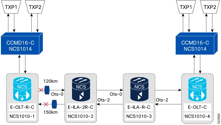
When there is a line unidirectional fiber cut on a NCS 1010 network, alarms are raised and suppressed at the respective ports of each node.

The following figure displays line unidirectional fiber cut on a NCS 1010:

Figure 1. Unidirectional Fiber Cut on Line

The following table lists the alarms that are raised and suppressed at the respective ports of each node:

Table 1. Active and Suppressed Alarms

NODE

Active Alarms

Ports where alarms are raised

Suppressed Alarms

Ports where alarms are suppressed

NCS 1010 - 1

  • Rx-LOC

  • INGRESS-AUTO-LASER-SHUT

  • EGRESS-AUTO-LASER-SHUT

  • Raman-AUTO-LASER-SHUT

  • APC-BLOCKED-TX

  • APC-BLOCKED-RX

  • RAMAN-TUNE-FAILED

Line OTS 0/0/0/0

Rx-LOS-P

  • Line OTS 0/0/0/0

  • DFB 0/0/0/0

  • OSC 0/0/0/0

  • OTS-OCH 0/0/0/0/x

    x is channel id

TX-POWER-FAIL-LOW

OTS-OCH 0/0/0/com-port/channel

TX-POWER-FAIL-LOW

OTS-OCH 0/0/0/0/channel

NCS1010 – 2 (ots - 0)

  • Rx-LOS-P

  • EGRESS-AUTO-LASER-SHUT

  • Raman-AUTO-LASER-SHUT

  • APC-BLOCKED-TX

  • RAMAN-TUNE-FAILED

Line OTS 0/0/0/0

Rx-LOS-P

OTS-OCH 0/0/0/0/x

x is channel id

TX-POWER-FAIL-LOW

OTS-OCH 0/0/0/0/channel

NCS1010 – 2 (ots - 2)

  • EGRESS-AUTO-LASER-SHUT

  • APC-BLOCKED-TX

Line OTS 0/0/0/2

TX-POWER-FAIL-LOW

OTS-OCH 0/0/0/2/channel

NCS1010 – 3 (ots - 0)

Rx-LOS-P

Line OTS 0/0/0/0

Rx-LOS-P

OTS-OCH 0/0/0/0/x

x is channel id

NCS1010– 3 (ots - 2)

  • EGRESS-AUTO-LASER-SHUT

  • APC-BLOCKED-TX

Line OTS 0/0/0/2

TX-POWER-FAIL-LOW

OTS-OCH 0/0/0/0/2

NCS1010 – 4

  • INGRESS-AUTO-LASER-SHUT

  • APC-BLOCKED-RX

  • Rx-LOS-P

Line OTS 0/0/0/0

Rx-LOS-P

OTS-OCH 0/0/0/0/x

x is channel id

TX-POWER-FAIL-LOW

OTS-OCH 0/0/0/com-port/channel

NCS1014

Rx-LOS-P

OMS 0/0/slot/0

Bidirectional Fiber Cut on Line

When there is a line bidirectional fiber cut on a NCS 1010 network, alarms are raised and suppressed at the respective ports of each node.

The following figure displays line bidirectional fiber cut on a NCS 1010 network:

Figure 2. Bidirectional Fiber Cut on Line

The following table lists the alarms that are raised and suppressed at the respective ports of each node:

Table 2. Active and Suppressed Alarms

NODE

Active Alarms

Ports where alarms are raised

Suppressed Alarms

Ports where alarms are suppressed

NCS1010-1

  • Rx-LOC

  • INGRESS-AUTO-LASER-SHUT

  • EGRESS-AUTO-LASER-SHUT

  • Raman-AUTO-LASER-SHUT

  • APC-BLOCKED-TX

  • APC-BLOCKED-RX

  • RAMAN-TUNE-FAILED

Line OTS 0/0/0/0

Rx-LOS-P

  • Line OTS 0/0/0/0

  • DFB0/0/0/0

  • OSC0/0/0/0

  • OTS-OCH0/0/0/0/x

    x is channel id

TX-POWER-FAIL-LOW

OTS-OCH 0/0/0/com-port

TX-POWER-FAIL-LOW

OTS-OCH 0/0/0/0/channel

NCS1010 – 2 (ots - 0)

  • Rx-LOC

  • EGRESS-AUTO-LASER-SHUT

  • Raman-AUTO-LASER-SHUT

  • APC-BLOCKED-TX

  • RAMAN-TUNE-FAILED

Line OTS 0/0/0/0

Rx-LOS-P

  • Line OTS 0/0/0/0

  • DFB 0/0/0/0

  • OSC 0/0/0/0

  • OTS-OCH 0/0/0/x

    x is channel id

TX-POWER-FAIL-LOW

OTS-OCH 0/0/0/0/channel

NCS1010– 2 (ots - 2)

  • EGRESS-AUTO-LASER-SHUT

  • APC-BLOCKED-TX

Line OTS 0/0/0/2

TX-POWER-FAIL-LOW

OTS-OCH 0/0/0/2/channel

NCS1010 – 3 (ots - 0)

Rx-LOS-P

Line OTS 0/0/0/0

Rx-LOS-P

OTS-OCH 0/0/0/0/x

x is channel id

NCS1010– 3 (ots - 2)

  • EGRESS-AUTO-LASER-SHUT

  • APC-BLOCKED-TX

Line OTS 0/0/0/2

TX-POWER-FAIL-LOW

OTS-OCH 0/0/0/2/channel

NCS1010 – 4

  • INGRESS-AUTO-LASER-SHUT

  • APC-BLOCKED-RX

  • Rx-LOS-P

Line OTS 0/0/0/0

Rx-LOS-P

OTS-OCH 0/0/0/0/x

x is channel id

TX-POWER-FAIL-LOW

OTS-OCH 0/0/0/com-port/channel

NCS1014

Rx-LOS-P

OMS 0/0/slot/0

Fiber Cut Between CCMD and OLT

When a fiber cut occurs between CCMD and OLT, alarms are raised and suppressed at the respective ports of each node.

The following figure displays fiber cut between CCMD and OLT:

Figure 3. Fiber Cut Between CCMD and OLT

The following table lists the alarms that are raised and suppressed at the respective ports of each node:

Table 3. Active and Suppressed Alarms

Condition

NODE

Active Alarms

Ports where alarms are raised

Suppressed Alarms

Ports where alarms are suppressed

CCMD Rx Fiber Cut

NCS1014

Rx-LOS-P

OMS 0/0/slot/0

CCMD Tx Fiber Cut

NCS1010 - 1

Rx-LOS-P

Line OTS 0/0/0/x

x is a com port

Rx-LOS-P

OTS-OCH 0/0/0/x/y

x is com port

y is channel id

CHANNEL-NOISE-LOADED

OTS-OCH 0/0/0/0/y

y is channel id

High Back Reflection Condition on Line Tx Port

When there is a high back reflection condition on the line Tx port, Egress EDFA goes into Automatic Power Reduction (APR) mode, and alarms are raised at the respective ports of each node.

The following figure displays high back reflection condition on the line Tx port:

Figure 4. High Back Reflection Condition on the Line Tx port

The following table lists the alarms that are raised at the respective ports of each node:

Table 4. Active Alarms

NODE

Active Alarms

Ports where alarms are raised

NCS1010 - 1

  • TX-POWER-FAIL-LOW

  • High-TX-BR-PWR

  • APC-BLOCKED-TX

Line OTS 0/0/0/0

NCS1010 – 2 (ots - 2)

APC-TARGET-PSD-NOT-MET-TX

Line OTS 0/0/0/2

NCS1010 – 3 (ots - 2)

APC-TARGET-PSD-NOT-MET-TX

Line OTS 0/0/0/2

NCS1010 – 4

APC-TARGET-PSD-NOT-MET-RX

Line OTS 0/0/0/0

High Back Reflection Condition on Line Rx RAMAN Port

When there is a high back reflection on the Line Rx Raman port, RAMAN pumps goes into Automatic Power Reduction (APR) mode, and alarms are raised at the respective ports of each node.

The following figure displays high back reflection condition on the line Rx RAMAN port:

Figure 5. High Back Reflection Condition on the Line Rx RAMAN Port

The following table lists the alarms that are raised at the respective ports of each node:

Table 5. Active Alarms

NODE

Active Alarms

Ports where alarms are raised

NCS1014

Rx-LOS-P

OMS 0/0/x/0

x is slot id

NCS1010 - 1

  • High-RX-BR-PWR

  • APC-OUT-OF-RANGE-RX

  • RT- BLOCKED

Line OTS 0/0/0/0

High Span Loss on Line Tx Port

When high span loss occurs on the line Tx port, alarms are raised at the respective ports of each node.

The following figure displays high span loss on line Tx port:

Figure 6. High span loss on Line Tx Port

The following table lists the alarms that are raised at the line Tx port:

Table 6. Active Alarms

NODE

Active Alarms

Ports where alarms are raised

NCS1010 – 2 (ots - 0)

Span Loss Value Out Of Range

Line OTS 0/0/0/0

NCS1010 – 2 (ots - 2)

APC-OUT-OF-RANGE-TX

Line OTS 0/0/0/2

High Span Loss on Line Rx Port

When high span loss occurs on the line Rx, alarms are raised at the respective ports of each node.

The following figure displays high span loss on the line Rx port:

Figure 7. High span loss on Line Rx port

The following table lists the alarms that are raised at the line Rx port:

Table 7. Active Alarms

NODE

Active Alarms

Ports where alarms are raised

NCS1010 - 1

  • Span Loss Value Out Of Range

  • APC-BLOCKED-RX

Line OTS 0/0/0/0

Single Channel Failure due to Bidirectional Fiber Cut on Line

When there is a bidirectional fiber cut on the line, single channel failure occurs, and alarms are raised at each node's port.

The following figure displays single channel failure due to bidirectional fiber cut on line:

Figure 8. Single Channel Failure due to Bidirectional Fiber Cut on Line

The following table lists the alarms that are raised at the respective ports of each node:

Table 8. Active Alarms

NODE

Active Alarms

Ports where alarms are raised

NCS1010 - 4

Rx-LOS-P

OTS-OCH 0/0/0/x/y

x is com port

y is channel number

CHANNEL-NOISE-LOADED

OTS-OCH 0/0/0/0/y

y is channel id

NCS1014 - 1

Rx-LOS-P

OCH 0/0/0/x/y

x is slot id

y is port number

Single Channel Failure due to Unidirectional Fiber Cut at TXP-Tx

When there is a unidirectional fiber cut at TXP-Tx, single channel failure occurs, and alarms are raised at each node's port.

The following figure displays single channel failure due to unidirectional fiber cut at TXP-Tx:

Figure 9. Single Channel Failure due to Unidirectional Fiber Cut at TXP-Tx

The following table lists the alarms that are raised at the respective ports of each node:

Table 9. Active Alarms

NODE

Active Alarms

Ports where alarms are raised

NCS1010 - 4

Rx-LOS-P

OTS-OCH 0/0/0/x/y

x is com port

y is channel number

CHANNEL-NOISE-LOADED

OTS-OCH 0/0/0/0/y

y is channel id

NCS1014

Rx-LOS-P

OCH 0/0/x/y

x is slot id

y is port number

Single Channel Failure due to Unidirectional Fiber Cut at TXP-Rx

When there is a unidirectional fiber cut at TXP-Rx, a single channel failure occurs, and no alarms are raised at each node's port.

The following figure displays single channel failure due to unidirectional fiber cut at TXP-Rx:

Figure 10. Single Channel Failure due to Unidirectional Fiber Cut at TXP-Tx
Table 10. Alarms

NODE

Active Alarms

NCS1010 - 4

No Alarm

NCS1014

No Alarm