Connection Verification

This chapter describes the tasks related to verify connection between NCS 1010 line cards, line card and breakout panel, and line card and Mux/Demux panel.

Power Data Reading

Photodiodes (PDs) are optical power monitors that are present on all input and aggregated output ports to monitor power levels. Some PD monitors are enabled with tone-detection capability.

Table 1. NCS1K-BRK-8 Calibrated Port References

Photodiode

Port Calibrated

Port Label (Direction)

Minimum Power

Maximum Power

Dynamic Range

PD 1 to PD 8

MPO-16 input ports

0 to 7 (TX)

–20

10

30

PD 9 to PD 16

MPO-16 output ports

0 to 7 (RX)

–20

10

30

PD 17

MPO input fiber 1

COM

–30

10

40

Table 2. NCS1K-BRK-24 Calibrated Port References

Photodiode

Port Calibrated

Port Label (Direction)

Minimum Power

Maximum Power

Dynamic Range

PD 1 to PD 8

MPO-16 input ports

0 to 23 (TX)

–20

10

30

PD 9 to PD 11

MPO-16 output ports

0 to 2 (RX)

–20

10

30

PD 12 to PD 14

3 to 5 (RX)

PD 15 to PD 17

6 to 8 (RX)

PD 18 to PD 20

9 to 11 (RX)

PD 21 to PD 23

12 to 14 (RX)

PD 24 to PD 26

15 to 17 (RX)

PD 27 to PD 29

18 to 20 (RX)

PD 30 to PD 32

21 to 23 (RX)

PD 33

MPO input fiber 1

COM

–30

10

40

Table 3. NCS1K-MD-32x-y Calibrated Port References

Photodiode

Port Calibrated

Port Label (Direction)

Minimum Power

Maximum Power

Dynamic Range

PD 1 to PD 32

32 LC input ports

0 to 31 (RX)

–30

10

40

PD 33

COM-RX

COM (RX)

–10

23

33

PD 34

COM-TX

COM (TX)

–35.5

20

55.5

PD 35

COM-RX

COM (TX)

–40

0

40

PD 361

COM-RX

COM (RX)

–24

5

30

1 This Photo diode refers only to OOB (191.175GHz) frequency

Connection Verification

Connection verification checks the connection between the OLT-C line card and all the other passive modules to avoid miscabling during the node installation. This task generates a specific probe signal from the dedicated Connection Verification Tunable Laser (CV-TL) available at COM-RX-2 (at a given frequency and power) and detects the probe signal on:

  • The same OLT-C line card

  • The passive modules (Mux/Demux panel or breakout panel) connected to the OLT-C line card

  • A different unit (OLT-C line card or passive module) belonging to the same NE

  • An optical interface (Router ports or Transponder) connected to the OLT-C line card

Connection verification uses a probe signal or adds a low frequency ON/OFF modulation tone transmitting a given tone pattern at 5 Hz (200 ms bit time). The tone pattern length ranges 4–32 bytes (including an alignment byte) and it includes the Cable-IDs of the cables in the connection and in case also the optical frequency of the specific connection.


Note


The Connection Verification feature requires that 'tone-pattern' and 'tone-pattern-expected' be the same length.


The Cable-ID is generated by the Optical Node Controller supervising the complete NE.

The connection verification process uses the out-of-band (OOB) WSS frequencies (191.150–191.3375 THz) to reach the Optical Interfaces connected to the OLT-C line card via Mux/Demux panel.

Line Card and Passive Modules Connection Verification

This section describes the connection verification between OLT-C line card and passive modules that are connected to ADD/DROP-i ports and the association between each passive modules and the related OLT-C line card USB management port.

Connection verification is performed using the OOB channel with CV-TL tuned at 191.175 THz. To univocally identify the optical path under test, the CV-TL is modulated with a low-frequency pattern including the Cable-ID of the connection.

For connection verification toward Mux/Demux panel, the CV-TL at COM-RX-2 port is routed to the DROP-1 or DROP-2 ports. The CV-TL is checked at the PD 36 inside the Mux/Demux panel. CV-TL verifies the correspondence between the specific module and management USB port. The connection verification loopback performs verification of the full optical path. The loopback checks the connection verification signal at PD 24/25 filtered monitors available on OLT-C line card ADD-1 or ADD-2 ports.

To detect the tone pattern on the connection verification signal, the following thresholds are set on the different monitors points:

  • Mux/Demux panel at PD 36 ON-threshold = –3dBm

  • Breakout panel loopback PD ON-threshold = –3dBm

  • OLT-C line card ADD ports at PD 24/25 ON-threshold = –5dBm

  • OLT-C line card COM-TX-2 port ON-threshold = –21dBm

For connection verification toward the breakout panels, the CV-TL at the COM-RX-2 port is routed to the first fiber of the specific MPO connector (port DROP-i with i=4, 12, 20, 28). The connection verification signal is checked at the monitors present in the breakout panels on the loopback path. This verifies the correspondence between the specific module and management USB port. The verification of the full optical path is performed by checking the connection verification signal at the COM-TX-2 port.

All the monitors receiving a connection verification signal detects and buffers the Cable-ID pattern encoded in the tone to allow the connection verification process by the node controller.

The connection verification signal loopback inside the breakout panel is replicated on all the output port on the MPO connector. In this way, it is possible to verify the loss of the MPO cable on the different fibers checking the connection verification signal power levels at the different ADD-i ports. This function requires a “diverse routing” between WSS Mux and Demux sections.

Side-to-Side Connection Verification

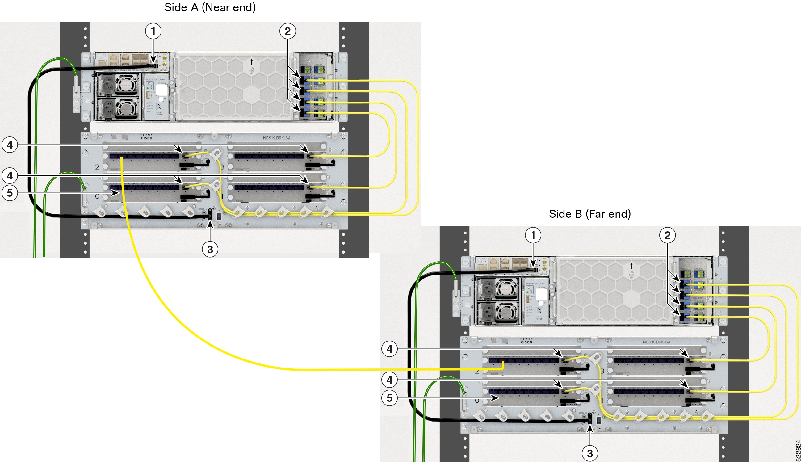
This section describes the connection verification between the different OLT units that are deployed on different sides of a multidegree ROADM node. The interconnection between the different OLT faced on the different sides of a multidegree ROADM is performed via LC patch-cords interconnection between the MPO ports of NCS1K-BRK-8 modules. The following figure shows the Side-to-Side connection between the OLT nodes through NCS1K-BRK-8 modules.

Figure 1. NCS 1010 Optical Line System Side-to-Side Connection
The image shows the Side-to-Side connection between the OLT nodes in multidegree ROADM through the NCS1K-BRK-8 modules.
1 EITU USB 2.0 Port
2 OLT-C Line Card Add/Drop MPO Ports
3 NCS1K-BRK-8 USB 2.0 Port
4 NCS1K-BRK-8 MPO Ports
5 NCS1K-BRK-8 LC Cable

The connection verification process is performed using the OOB channel with CV-TL tuned at frequency 191.17 THz. To univocally identify the optical path under test, the CV-TL is modulated with a low-frequency pattern including the Cable-ID of the connection.

The connection verification signal that is generated by the CV-TL is routed to the specific WSS DROP-i ports used for the side-to-side interconnection. It is verified at the monitors available at the NCS1K-BRK-8 input ports that are connected to the OLT-C line card at the other side.

All the monitors receiving a connection verification signal detects and buffers the Cable-ID pattern encoded in the tone. This method allows the proper connection verification process by the node controller.

The side-to-side connection verification is performed after the connection verification between the OLT-passive units to have a complete view of the interconnection between the OLT and each specific NCS1K-BRK-8 module.

The side-to-side connection verification check is performed without any traffic present on the path.

To properly detect the tone pattern on the side-to-side connection verification signal, an ON-threshold of –5dBm is provisioned on all PDs at the DIR-i-RX ports of the NCS1K-BRK-8 module.

Verify Connection for Side-to-Side Nodes

This task describes how to verify connection between different NCS 1010 OLT nodes on different sides of the multidegree ROADM nodes.

Procedure

Step 1

Start tone-pattern on OTS controller.

RP/0/RP0/CPU0:ios#tone-pattern controller ots 0/0/0/5 start
Tue May 10 11:37:51.597 UTC
Tone pattern started

Note


The following alarm is raised after the tone-pattern is started.

0/0 Minor Controller 07/13/2022 21:21:02 UTC
Ots0/0/0/5 - Tone Generation In Progress 

Step 2

Start tone-pattern-detect on OMS controller on one side.

RP/0/RP0/CPU0:ios#tone-pattern-detect controller oms 0/2/0/9 start
Tue May 10 11:38:03.775 UTC
Tone pattern detect started

Step 3

Start tone-pattern-detect on OCH controller on the other side.

RP/0/RP0/CPU0:ios#tone-pattern-detect controller och 0/2/0/1 start
Tue May 10 11:38:03.775 UTC
Tone pattern detect started

Step 4

Use the tone-info command to check for successful connection verification on OMS controller.

RP/0/RP0/CPU0:ios#show controllers oms 0/2/0/9 tone-info

Step 5

Use the tone-info command to check for successful connection verification on OCH controller.

RP/0/RP0/CPU0:ios#show controllers och 0/2/0/1 tone-info

Step 6

Stop the tone-pattern-detect on the OCH controller.

RP/0/RP0/CPU0:ios#tone-pattern-detect controller och 0/2/0/1 stop
Tue May 10 11:50:36.185 UTC
Tone pattern detect stoped

Step 7

Stop the tone-pattern-detect on the OMS controller.

RP/0/RP0/CPU0:ios#tone-pattern-detect controller oms 0/2/0/9 stop
Tue May 10 11:50:36.185 UTC
Tone pattern detect stoped

Step 8

Stop the tone-pattern-detect on the OTS controller.

RP/0/RP0/CPU0:ios#tone-pattern controller ots 0/0/0/5 stop
Tue May 10 11:50:45.837 UTC
Tone pattern stopped

Line Card and Optical Interfaces Connection Verification

This section describes the connection verification between OLT nodes and the optical interfaces that are connected to Mux/Demux panel and breakout modules.

Verify Connection for NCS 1000 32-Channel Mux/Demux Patch Panel

The connection verification procedure checks the connection between OLT-C line card and the two Mux/Demux panels.

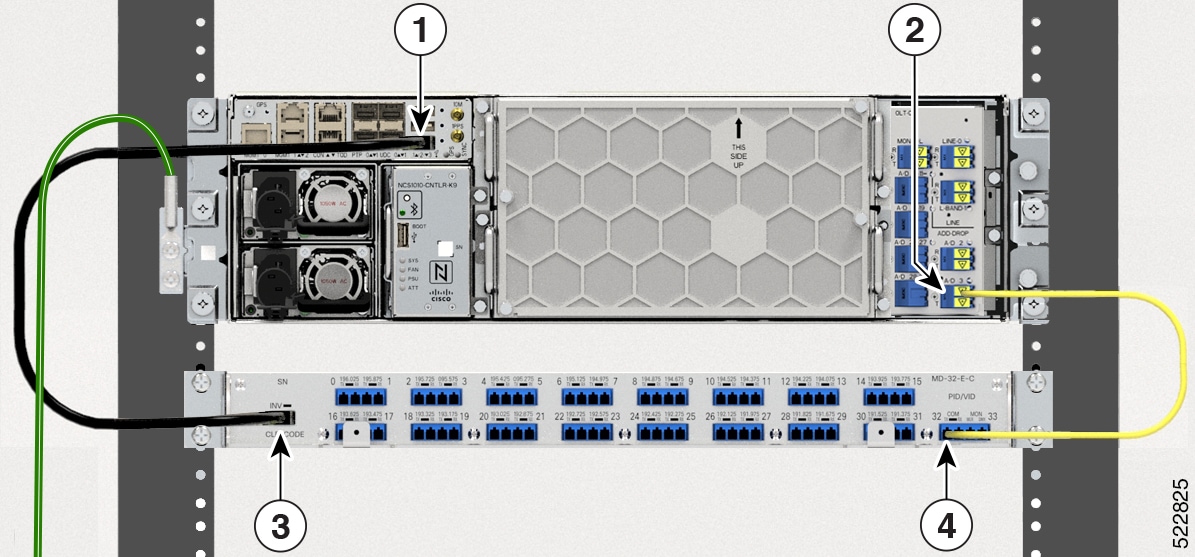
The OLT-C line card and the Mux/Demux panels are connected as shown in the following image:

Figure 2. NCS 1010 and NCS 1000 32-Channel Mux/Demux Patch Panel Connection
The image shows the connection between the NCS 1010 OLT node and the Mux/Demux panel.
1 EITU USB 2.0 Port
2 OLT-C Line Card Add/Drop 3 LC Port
3 Mux/Demux Panel USB 2.0 Port
4 Mux/Demux Panel COM Port

. The identification/verification of the two Mux/Demux panels is performed by checking the connection verification signal at the monitor present on the OOB loop (PD 36 signal). The monitor detects and buffers the Cable-ID encoded in the tone pattern.

In Mux/Demux panel, the PD monitors available on the CH-i-RX ports of each module check the connection verification signal coming from the optical interfaces TX port on the Add path.

The tone detection capability is available on the PD monitors at the CH-i-RX ports and on the loopback path and it is “armed” provisioning on the Mux/Demux panels:

  • ON threshold (to determine the “1” or “0” bit)

  • the sampling rate

  • the pattern lengths (number of bytes)

  • the list of PD to be “armed”

Parallel tone acquisitions are allowed on whole ports of the Mux/Demux panel.

Once the bit-pattern encoded in the tone is detected, the information is stored to be retrieved by the node controller and the tone acquisition is stopped until the next “rearm”.

Default ON-threshold to detect the tone pattern on the Mux/Demux signal are:

  • –15dBm on all PDs at CH-i-RX ports

  • –3dBm on the PD33 on the loopback path

This task describes on how to verify connection between the NCS 1010 OLT-C line card and Mux/Demux panel.

Procedure

Step 1

Configure the OTS controller to generate the tone for connection verification.

Example:
RP/0/RP0/CPU0:(config)#controller ots 0/0/0/3
RP/0/RP0/CPU0:(config-Ots)#tone-rate 25
RP/0/RP0/CPU0:(config-Ots)#tone-frequency 191.175   ( OOB frequency )
RP/0/RP0/CPU0:(config-Ots)#tone-pattern abcd1234
RP/0/RP0/CPU0:(config-Ots)#commit

tone-pattern length must be 4–32 hexadecimal characters.

Step 2

Configure the OMS controller to detect the tone for connection verification.

Example:
RP/0/RP0/CPU0:(config)#controller oms 0/2/0/32 
RP/0/RP0/CPU0:(config-Oms)#tone-rate 25
RP/0/RP0/CPU0:(config-Oms)#tone-pattern-expected abcd1234
RP/0/RP0/CPU0:(config-Oms)#tone-detect-oob 
RP/0/RP0/CPU0:(config-Oms)#commit

tone-pattern-expected value must be the same as the tone-pattern value.

tone-detect-oob must be configured on the OMS x/x/x/32 for Mux/Demux panel.

Step 3

Start tone-pattern on the OTS controller.

Example:
RP/0/RP0/CPU0:#tone-pattern controller ots 0/0/0/3 start 
Tue May 10 11:37:51.597 UTC
Tone pattern started

When tone generation is in progress on the OTS interface, the tone generation on other OTS interfaces is not allowed until the current tone generation is stopped.

Step 4

Use the tone-pattern-detect command to start the detection of tone pattern.

Example:

The following is a sample on starting the tone pattern detection on the OMS controller.

RP/0/RP0/CPU0:#tone-pattern-detect controller oms 0/2/0/32 start 
Tue May 10 11:38:03.775 UTC
Tone pattern detect started

Step 5

Use the tone-info command to check for successful connection verification.

Example:

The following is a sample to view the Tone Info for successful connection verification on the OMS controller.

RP/0/RP0/CPU0:#show controllers oms 0/2/0/32 tone-info 
Tue May 10 11:41:18.847 UTC

Tone Info:


Tone Rate : 25 bits/second

Tone Pattern Expected(Hex value) : abcd1234

Tone Pattern Received(Hex value) : abcd1234

Tone Detected OOB :  Enabled

Detection State: Success

Step 6

After successful connection verification, stop tone-pattern-detect on the OMS controller and tone-pattern on the OTS controller.

Example:
RP/0/RP0/CPU0:#tone-pattern-detect controller oms 0/2/0/32 stop
Tue May 10 11:50:36.185 UTC
Tone pattern detect stoped
RP/0/RP0/CPU0:#tone-pattern controller ots 0/0/0/3 stop
Tue May 10 11:50:45.837 UTC
Tone pattern stopped

Verify Connection for NCS1K-BRK-8 Panel

The connection verification procedure checks the connection between the OLT-C line card and each NCS1K-BRK-8 panel to match the different module instances with respect to the OLT-C MPO connectors.

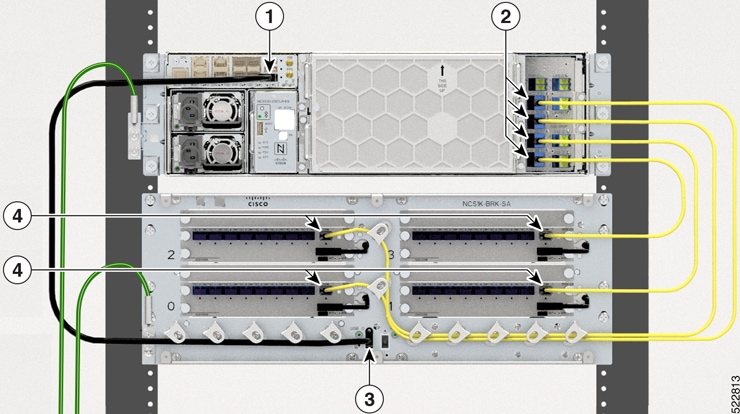
The OLT-C line card and the NCS1K-BRK-8 module are connected as shown in the following image:

Figure 3. NCS 1010 and NCS1K-BRK-8 Connection
The image shows the connection between the NCS 1010 OLT node and the NCS1K-BRK-8 panel.
1 EITU USB 2.0 Port
2 OLT-C Line Card Add/Drop MPO Ports
3 NCS1K-BRK-8 USB 2.0 Port
4 NCS1K-BRK-8 MPO Ports

The OLT-C line card performs connection verification between the OLT-C Line Card and the NCS1K-BRK-8 panels as described in Line Card and Passive Modules Connection Verification.

The identification/verification of the NCS1K-BRK-8 panel is performed by checking the connection verification signal at the monitor present on the OOB loop (PD17 for the NCS1K-BRK-8 module).


Note


Connection verification is not supported for NCS1K-BRK-16 and NCS1K-BRK-24 panels.


Each pair of OLT-C line cards that are deployed on two different sides of a multidegree ROADM performs connection verification on Side-to-Side interface as described in Side-to-Side Connection Verification. In this case, the PD monitors available on the DIR-i-RX ports of the NCS1K-BRK-8 module detect the connection verification signal coming from the OLT-C Line Card on the other side.

In the NCS1K-BRK-8 panel, the PD monitors available on the CH-i-RX ports of each NCS1K-BRK-8 panel checks the connection verification signal coming from the optical interfaces TX port on the Add path.

The tone detection capability is available on all the PD monitors present on the input and output ports and on the loopback path of the NCS1K-BRK-8 panel. It is “armed” provisioning on the modules:

  • ON threshold (to determine the “1” or “0” bit)

  • Sampling rate

  • Pattern lengths (number of bytes)

  • List of PD to be “armed"

Parallel tone acquisitions are allowed on whole ports of the modules.

Once the bit-pattern encoded in the tone is detected, the information is stored to be retrieved by the node controller and the tone acquisition is stopped until the next “rearm.”

Default ON-threshold to detect the tone pattern on the connection verification signal are:

  • –5dBm on all PDs at DIR-i-RX or CH-i-RX ports

  • –3dBm on the PDs on the loopback path of each module

This task describes on how to verify the connection between the NCS 1010 OLT-C line card and NCS1K-BRK-8 panel.

Procedure

Step 1

Configure the OTS controller to generate the tone for connection verification.

Example:
RP/0/RP0/CPU0:(config)#controller ots 0/0/0/4
RP/0/RP0/CPU0:(config-Ots)#tone-rate 25
RP/0/RP0/CPU0:(config-Ots)#tone-frequency 191.175   ( OOB frequency )
RP/0/RP0/CPU0:(config-Ots)#tone-pattern abcd1234
RP/0/RP0/CPU0:(config-Ots)#commit

tone-pattern length must be 4–36 hexadecimal characters.

Step 2

Configure the OMS controller to detect the tone for connection verification.

Example:
RP/0/RP0/CPU0:(config)#controller oms 0/2/0/8 
RP/0/RP0/CPU0:(config-Oms)#tone-rate 25
RP/0/RP0/CPU0:(config-Oms)#tone-pattern-expected abcd1234
RP/0/RP0/CPU0:(config-Oms)#tone-detect-oob 
RP/0/RP0/CPU0:(config-Oms)#commit

tone-pattern-expected value must be same as the tone-pattern value.

tone-detect-oob must be configured on the OMS x/x/x/8 for NCS1K-BRK-8.

Step 3

Start tone-pattern on the OTS controller.

Example:
RP/0/RP0/CPU0:#tone-pattern controller ots 0/0/0/4 start 
Tue May 10 11:37:51.597 UTC
Tone pattern started

When tone generation is in progress on the OTS interface, the tone generation on other OTS interfaces is not allowed until the current tone generation is stopped.

Step 4

Use the tone-pattern-detect command to start the detection of tone pattern.

Example:

The following is a sample on starting the tone pattern detection on the OMS controller.

RP/0/RP0/CPU0:#tone-pattern-detect controller oms 0/2/0/8 start 
Tue May 10 11:38:03.775 UTC
Tone pattern detect started

Step 5

Use the tone-info command to check for successful connection verification.

Example:

The following is a sample to view the Tone Info for successful connection verification on the OMS controller.

RP/0/RP0/CPU0:#show controllers oms 0/2/0/8 tone-info 
Tue May 10 11:41:18.847 UTC

Tone Info:


Tone Rate : 25 bits/second

Tone Pattern Expected(Hex value) : abcd1234

Tone Pattern Received(Hex value) : abcd1234

Tone Detected OOB :  Enabled

Detection State: Success

Step 6

After successful connection verification, stop tone-pattern-detect on the OMS controller and tone-pattern on the OTS controller.

Example:
RP/0/RP0/CPU0:#tone-pattern-detect controller oms 0/2/0/8 stop
Tue May 10 11:50:36.185 UTC
Tone pattern detect stoped
RP/0/RP0/CPU0:#tone-pattern controller ots 0/0/0/4 stop
Tue May 10 11:50:45.837 UTC
Tone pattern stopped

Connection Verification on OTS Controller

This task describes how to check OTS interface connectivity on OLT nodes.

Procedure


Step 1

Start tone-pattern on OTS controller.

Example:

RP/0/RP0/CPU0:ios#tone-pattern controller ots 0/0/0/2 start
Wed May 25 11:59:51.040 UTC
Tone pattern started

Step 2

Start tone-pattern-detect on OTS controller on one side.

Example:

RP/0/RP0/CPU0:ios#tone-pattern-detect controller ots 0/0/0/2 start
Wed May 25 12:00:03.271 UTC
Tone pattern detect started

Step 3

Check for successful connection verification on the Line 2 OTS controller.

Example:

RP/0/RP0/CPU0:ios#show controllers ots 0/0/0/2 tone-info 
Wed May 25 12:00:11.393 UTC

Tone Info:

Tone Frequency : 191.1750000 THz

Tone Rate : 20 bits/second

Tone Pattern(Hex value) : abcd1234

Tone Pattern Expected(Hex value) : abcd1234

Tone Pattern Received(Hex value) : abcd1234

Tone Detected OOB :  Enabled

 Detection State: Success 

Step 4

Stop the tone-pattern-detect on the OTS controller.

Example:

RP/0/RP0/CPU0:ios#tone-pattern-detect controller ots 0/0/0/2 stop
Wed May 25 12:00:56.540 UTC
Tone pattern detect stoped

Step 5

Stop the tone-pattern on the OTS controller.

Example:

RP/0/RP0/CPU0:ios#tone-pattern controller ots 0/0/0/2 stop
Wed May 25 12:01:04.226 UTC
Tone pattern stopped