Layer 1 Encryption

This chapter describes how to configure the IKEv2 protocol and layer 1 encryption for NCS 1004.


Note


In this chapter, "layer 1 encryption" is referred to as "OTNSec".


Table 1. Feature History

Feature Name

Release Information

Feature Description

Encryption Support on 1.2TL Card

Cisco IOS XR Release 7.3.1

AES 256 GCM authenticated OTNSec encryption on 1.2TL line cards is supported. It uses only pre-shared keys for authentication. Optical encryption secures the communications link in and out of a facility, rendering all data undecipherable to hackers who tap into networks.

Encryption Support on OTN-XP Card

Cisco IOS XR Release 7.8.1

AES 256-GCM authenticated OTNSec encryption is supported on the OTN-XP card. The encryption is enabled on the ODUC4 controller.

This encryption secures the data across different datapaths of the OTN-XP card.

Encryption for 10G clients and 100GE clients on OTN-XP Card

Cisco IOS XR Release 7.9.1

OTN-XP card now supports AES 256-GCM authenticated OTNSec encryption for 10G and 100GE clients in the 40x10G-4x100G-MXP mode. As this authentication method uses a key size of 256 bits, it provides considerably strong cryp­togra­phy acceptable by enterprise, and public sector organizations.

The Need for High Speed Encryption

Most of the emphasis on protecting networks today is focused on protecting data within data center. However, the infrastructure of networks that connect these data centers are as vulnerable to calculated attacks as the data centers themselves. As more sensitive information gets transmitted across fiber-optic networks, cyber criminals are increasingly turning their attention to intercepting the data when it travels across the network.

With the increase in network or fiber optic hacks, the need for data protection is paramount. Encryption of any data that leaves the data centers is becoming an important requirement for cloud operators. Optical encryption secures everything on the communications link in and out of a facility rendering all data undecipherable to any hacker that taps into the fiber strand. Protecting data at high speeds or lines rates is a requirement for data centers today.

The Cisco NCS 1004 brings to you AES256 based OTNSec encryption for 100GE and OTU4 clients. Encryption is supported on the 1.2T and 1.2TL cards.

From Release 7.8.1, layer 1 encryption is supported on the OTN-XP card. For OTN-XP card, different LC modes have different client-side controllers. Hence, encryption has to be enabled under the common ODUCn controller. In release 7.8.1, the OTNSec encryption is enabled under the ODUC4 controller for the following modes with a trunk rate of 400G and with CFP2 DCO Greylock 2 pluggable:

  • 4x100G-MXP of 4x100G-MX-400G-TXP LC mode

  • FC-MXP mode

From Cisco IOS XR Release 7.9.1, in addition to the 10G client, with 40x10G-4x100G-MXP LCMode in OTN-XP card, you can enable encryption on the ODUC1, ODUC2, ODUC3, and ODUC4 controller for trunk rates 100-400G.

This encryption provides more flexibility across different LC modes and datapaths of the OTN-XP card.

OTNSec encryption uses the IKEv2 protocol to negotiate and establish the IKEv2 and OTNSec Security Associations (SA). IKEv2 is used for authentication of the devices in an encryption session, and the protocol provides pre-shared keys (PSK) or RSA certificate-based authentication. The IKEv2 datagrams are carried as payloads using the point-to-point protocol (PPP) over the GCC channel.

To implement this, an IKE session is established between the two endpoints, Site A and Site B, for overhead control plane communication between the two data centers. Data is then encrypted at Site A using OTNSec encryption and decrypted at Site B.

Figure 1. OTNSec Site-to-Site Example and Components

The recommended deployment is to have a single IKEv2 session running over a GCC2 channel per trunk port which creates the child SAs for each of the OTNSec controllers that are configured on the trunk port.

IKEv2 Overview

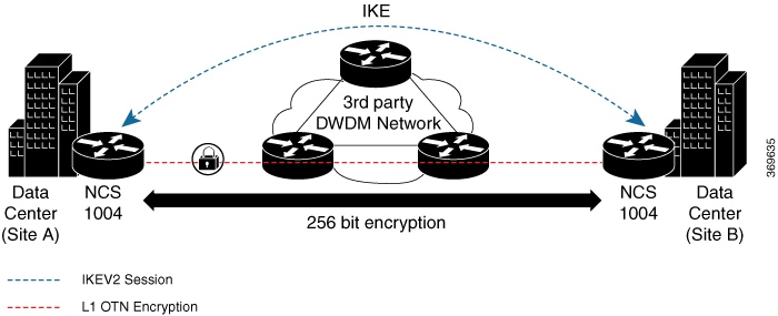
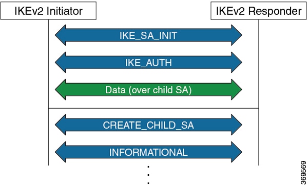
Internet Key Exchange Version 2 (IKEv2) is a request and response encryption that establishes and handles security associations (SA) in an authentication suite, such as OTNSec, to ensure secure traffic. IKE performs mutual authentication between two endpoints and establishes an IKE Security Association (SA). All IKE communications consist of pairs of messages that include a request and a response. The pair is called an exchange or a request-response pair. The first two exchanges of messages establishing an IKE SA are called the IKE_SA_INIT exchange and the IKE_AUTH exchange; subsequent IKE exchanges are called either CREATE_CHILD_SA exchanges or INFORMATIONAL exchanges. IKEv2 uses sequence numbers and acknowledgments to provide reliability, and mandates some error-processing logistics and shared state management (windowing). IKEv2 does not process a request until it determines the requester. This helps to mitigate DoS attacks. IKEv2 provides built-in support for Dead Peer Detection (DPD), which periodically confirms the availability of the peer node. When there is no response from the peer node, the system attempts to establish the session again.

Figure 2. IKEv2 Exchanges

IKEv2 is defined in RFC 7296 and consists of the following constructs:

  • Keyring

    A keyring is a repository of symmetric and asymmetric pre-shared keys that is configured for a peer and identified using the IP address of the peer. The keyring is associated with an IKEv2 profile and therefore, caters to a set of peers that match the IKEv2 profile. This is a required configuration for the pre-shared keys authentication method that is used for NCS 1004.


    Note


    The certificate-based authentication that uses RSA signatures can be used instead of the keyring. If both methods of authentication are configured, the certificate-based authentication takes precedence. See IKEv2 Certificate-Based Authentication.


  • IKEv2 Profile

    An IKEv2 profile is a repository of nonnegotiable parameters of the IKE SA, such as authentication method and services that are available to the authenticated peers that match the profile. The profile match lookup is done based on the IP address of the remote identity. For security purposes, the IKE SAs have a lifetime that is defined in the IKEv2 profile. The lifetime range, in seconds, is from 120 to 86400. The SAs are rekeyed proactively before the expiry of the lifetime. The default lifetime is 86400. An IKEv2 profile must be attached to an OTNSec configuration on the ODU4 controllers or ODUC4 controllers on both the IKEv2 initiator and responder. This is a required configuration.


    Note


    Only one authentication method is supported for the local peer but multiple authentication methods can be configured for the remote peer.

    If both methods of authentication are configured , keyring and certificate trustpoint (see, IKEv2 Certificate-Based Authentication) in the profile, the remote peer can authenticate itself using either method. authentication remote [pre-shared| rsa-signature] can be used to exclusively control the remote authentication method. Similarly, authentication local [pre-shared | rsa-signature] can be used to exclusively configure local authentication method. If it is not configured, the certificate-based authentication takes precedence.


  • IKEv2 Proposal

    An IKEv2 proposal is a collection of transforms that are used in the negotiation of IKE SAs as part of the IKE_SA_INIT exchange. The IKE2 proposal must be attached to an IKEv2 policy. This is an optional configuration. The transform types used in the negotiation are as follows:

    • Encryption algorithm

    • Integrity algorithm

    • Pseudo-Random Function (PRF) algorithm

    • Diffie-Hellman (DH) group


    Note


    The IKEv2 proposal must have at least one algorithm of each type. It is possible to specify multiple algorithms for each type; the order in which the algorithms are specified determines the precedence.


  • IKEv2 Policy

    IKEv2 employs policies that are configured on each peer to negotiate handshakes between the two peers. An IKEv2 policy contains proposals that are used to negotiate the encryption, integrity, PRF algorithms, and DH group in the SA_INIT exchange. An IKEv2 policy is selected based on the local IP address. This is an optional configuration.


    Note


    The default IKEv2 proposal is used with default IKEv2 policy in the absence of any user-defined policy.


OTNSec Encryption Overview

OTNSec encryption in NCS 1004 has the following characteristics:

  • The OTN layer 1 security is supported over the OPU client payload.

  • The Galois-Counter-Mode (GCM) AES 256-bit security is the default cipher used for encryption and decryption of the OPU payloads.

  • Each client offers an independent encrypted channel in each direction.

  • There are two banks of 256-bit programmable key registers (current key and future key) that permit key updates through the software without interrupting traffic.

    Each key is associated with an Association Number [AN(1:0)] allowing up to four different numbers.

  • Interhost key exchange is supported through communication over GCC.

  • The encryption is supported in headless mode.

The OTNSec control plane generates two different keys, one for the transmit (Tx) side and the other for the receive (Rx) side. These keys are used by the line card to program the encryptor and decryptor blocks. These blocks encrypt and decrypt the data packets between the trunk ports of the two nodes. For security purposes, the keys have a lifetime. A key's lifetime specifies the time the key expires.

The key lifetime for the child SAs can be configured using the sak-rekey-interval which ranges from 30 seconds to 14 days. For example, if the sak-rekey-interval is configured for five minutes, a new key is generated by the OTNSec layer every five minutes. In the absence of a lifetime configuration, the default lifetime is 14.18 days. When the key reaches the maximum lifetime, it becomes invalid and the CRYPTO-KEY-EXPIRED alarm is raised. Volume-based rekeying is supported; it prevents the key from reaching the maximum lifetime. This allows the OTNSec layer to generate a new key when 70% of the lifetime (11 days) of the current key is over.

When the lifetime of the first key expires, it automatically rolls over to the next key. To achieve a hitless rollover, the lifetimes of the keys need to be overlapped so that for a certain period of time both keys are active. To maintain this seamless switchover, a key index table is maintained. Each key pair (Tx and Rx) is associated with an Association Number (AN). The index table allows up to four numbers (0,1, 2, and 3). When the keys are installed, the Rx AN number of node A must match the Tx AN number of node B. Also, the Tx AN number of node A must match the Rx AN number of node B. If there is a mismatch of the AN numbers between the peer nodes, the CRYPTO-INDEX-MISMATCH alarm is raised.

Prerequisites

  • Ensure that the required k9sec.rpm package is installed.

  • Configure the line card in the muxponder or muxponder slice mode using the following commands:

    • 1.2T Card:

      • muxponder mode:

        hw-module location location mxponder client-rate 100GE | OTU4

        hw-module location location mxponder trunk-rate {100G | 200G | 300G | 400G | 500G | 600G}

      • muxponder slice mode:

        hw-module location location mxponder-slice mxponder-slice-number client-rate 100GE | OTU4

        hw-module location location mxponder-slice trunk-rate { 100G | 200G | 300G | 400G | 500G | 600G }

    • 1.2TL Card:

      • muxponder mode:

        hw-module location location mxponder client-rate 100GE | OTU4

        hw-module location location mxponder trunk-rate {200G | 300G | 400G }

      • muxponder slice mode:

        hw-module location location mxponder-slice mxponder-slice-number client-rate 100GE | OTU4

        hw-module location location mxponder-slice trunk-rate { 200G | 300G | 400G }

    • OTN-XP Card:

      muxponder mode:

      hw-module location location mxponder-slice mxponder-slice-number trunk-rate 400G client-port-rate client-port-number lane lane-number client-type { 10GE | 100GE |OTU2 | OTU2e | 400GE | FC16 | FC32}

Limitations

  • Traffic is impacted for a few seconds if the RP fails or GCC2 control plane goes down, during a key rollover.

  • The sak-rekey-interval must be configured on the initiator and responder node.

Configuration Workflow

This section describes the workflow to configure IKEv2 and OTNSec encryption on NCS 1004. The authentication method used is pre-shared keys (PSKs).

Figure 3. L1 Encryption Workflow
Table 2. Workflow for Configuring IKEv2 and OTNSec Encryption on NCS 1004

Workflow Sequence

Details

IKE Configuration

Configuring an IKEv2 Proposal

(Optional) Configure an IKEv2 proposal manually;otherwise, the default IKEv2 proposal is used in the default IKEv2 policy.

The default IKEv2 proposal requires no configuration and is a collection of commonly used transforms types, which are as follows:
encryption cbc-aes-256
integrity sha512, sha384
prf sha512, sha384
dh 19, 20, 21

Configuring an IKEv2 Policy

(Optional) Configure an IKEv2 policy manually;otherwise, the default proposal associated with the default policy is used for negotiation.

Note


An IKEv2 policy with no proposal is considered incomplete.

Configuring a Keyring

Configure a keyring as the local or remote authentication method is a preshared key.

Configuring a IKEv2 Profile

Configure an IKEv2 profile.

Note

 
  • The IKEv2 profile must be attached to the OTNSec profile on both the IKEv2 initiator and the responder.

  • The DPD interval is 10 seconds. If there is no response from the peer node, it retries every two seconds with a maximum of five attempts. After five retries, the IKE session is brought down. NCS 1004 supports headless mode. Therefore, even though the control plane is down, traffic is not impacted because the encryption and decryption keys are still active on the line cards. The data path functions in a locally secure mode and the OTNSEC-LOCALLY-SECURED alarm is raised.

OTNSec Configuration

Configuring an OTNSec Policy

(Optional) Configure the OTNSec policy.

Configuring the GCC Interface

Configure the GCC2 interface.

Configuring OTNSec on ODU4 Controllers

Configure the ODU4 controller that is mapped to the HundredGigE controller for 1.2T and 1.2TL cards.

Configuring OTNSec on ODUC4 Controllers for OTN-XP Card

Configure the ODUC4 controller in the OTN-XP card. The ODUC4 controller is mapped to the 400GE client for the TXP datapath, and 4x100GE clients for the MXP datapath.

Verification

Verification

Verify the IKEv2 and OTNSec configuration.

Configuring an IKEv2 Proposal

To configure an IKEv2 proposal, use the following commands:

config

ikev2 proposal proposal-name

encryption {aes-gcm-256} {aes-gcm-128} {aes-cbc-256} {aes-cbc-192} {aes-cbc-128}

integrity {sha-1} {sha-256} {sha-384} {sha-512}

prf {sha-1} {sha-256} {sha-384} {sha-512}

dh {19} {20} {21}


Note


Configuring an AES-GCM encryption algorithm does not require configuring an integrity algorithm. AES-GCM and non-GCM algorithms cannot be configured in the same proposal. However, you can configure the AES-GCM and non-GCM algorithms under two different proposals and attach both the proposals to the same IKEv2 policy.


The following sample displays how to configure an IKEv2 proposal.

RP/0/RP0/CPU0:ios#configure
Thu Mar  7 19:19:30.259 UTC
RP/0/RP0/CPU0:ios(config)#ikev2 proposal proposal1
RP/0/RP0/CPU0:ios(config-ikev2-proposal-proposal1)#encryption aes-cbc-256
RP/0/RP0/CPU0:ios(config-ikev2-proposal-proposal1)#integrity sha-1
RP/0/RP0/CPU0:ios(config-ikev2-proposal-proposal1)#prf sha-256
RP/0/RP0/CPU0:ios(config-ikev2-proposal-proposal1)#dh 20
RP/0/RP0/CPU0:ios(config-ikev2-proposal-proposal1)#commit
Thu Mar  7 19:20:30.916 UTC
RP/0/RP0/CPU0:ios(config-ikev2-proposal-proposal1)#exit
RP/0/RP0/CPU0:ios(config)#exit
RP/0/RP0/CPU0:ios#show ikev2 proposal proposal1
Thu Mar  7 19:20:48.929 UTC

Proposal Name              : proposal1
=====================================================================================
Status                     : Complete
-------------------------------------------------------------------------------------
Total Number of Enc. Alg.  : 1
   Encr. Alg.              : CBC-AES-256
-------------------------------------------------------------------------------------
Total Number of Hash. Alg. : 1
   Hash. Alg.              : SHA 1
-------------------------------------------------------------------------------------
Total Number of PRF. Alg.  : 1
   PRF. Alg.               : SHA 256
-------------------------------------------------------------------------------------
Total Number of DH Group   : 1
   DH Group                : Group 20

Configuring an IKEv2 Policy

To configure an IKEv2 policy, use the following commands:

config

ikev2 policy policy-name

proposal proposal-name1 proposal-name2 proposal-name3

match address local { ipv4-address}

The following sample displays how to configure an IKEv2 policy.

RP/0/RP0/CPU0:ios#configure
Thu Mar  7 19:26:45.752 UTC
RP/0/RP0/CPU0:ios(config)#ikev2 policy mypolicy
RP/0/RP0/CPU0:ios(config-ikev2-policy-mypolicy)#proposal proposal1
RP/0/RP0/CPU0:ios(config-ikev2-policy-mypolicy)#match address local 10.1.1.1
RP/0/RP0/CPU0:ios(config-ikev2-policy-mypolicy)#commit
Thu Mar  7 19:29:25.043 UTC
RP/0/RP0/CPU0:ios(config-ikev2-policy-mypolicy)#exit
RP/0/RP0/CPU0:ios(config)#exit
RP/0/RP0/CPU0:ios#show ikev2 policy mypolicy
Thu Mar  7 19:30:30.343 UTC

Policy Name                           : mypolicy
===============================================================================
Total number of match local addr      : 1
   Match address local                : 10.1.1.1
-------------------------------------------------------------------------------
Total number of proposal attached     : 1
   Proposal Name                      : proposal1

Configuring a Keyring

To configure a keyring, use the following commands:

config

keyring keyring-name

peer peer-block name

address {ipv4-address [mask]}


Note


The IP address of the far-end node (remote node) must be used.


pre-shared-key {{key} {clear clear-text key} {local local key} {passwordencrypted key}}

Note


The key input can either be in clear text or in type 7 encrypted password format.


The following sample displays how to configure a keyring.

RP/0/RP0/CPU0:ios#configure
Thu Mar  7 19:33:14.594 UTC
RP/0/RP0/CPU0:ios(config)#keyring kyr1
RP/0/RP0/CPU0:ios(config-keyring-kyr1)#peer peer1
RP/0/RP0/CPU0:ios(config-keyring-kyr1-peer-peer1)#address 10.1.1.2 255.255.255.0
RP/0/RP0/CPU0:ios(config-keyring-kyr1-peer-peer1)#pre-shared-key password 106D000A064743595F
RP/0/RP0/CPU0:ios(config-keyring-kyr1-peer-peer1)#commit
Thu Mar  7 19:54:33.314 UTC
RP/0/RP0/CPU0:ios(config-keyring-kyr1-peer-peer1)#exit
RP/0/RP0/CPU0:ios(config-keyring-kyr1)#exit
RP/0/RP0/CPU0:ios(config)#exit
RP/0/RP0/CPU0:ios#show keyring kyr1
Thu Mar  7 19:58:07.135 UTC

Keyring Name                          : kyr1
===============================================================================
Total Peers                           : 1
-------------------------------------------------------------------------------
   Peer Name                          : peer1
   IP Address                         : 10.1.1.2
   Subnet Mask                        : 255.255.255.0
   Local PSK                          : Configured
   Remote PSK                         : Configured

Configuring a IKEv2 Profile

To configure an IKEv2 profile, use the following commands:

config

ikev2 profile profile-name

match identity remote address {ipv4-address [mask]}

keyring keyring-name

lifetime seconds


Note


The lifetime range, in seconds, is from 120 to 86400.


The following sample displays how to configure an IKEv2 profile.

RP/0/RP0/CPU0:ios#configure
Thu Mar  7 20:00:36.490 UTC
RP/0/RP0/CPU0:ios(config)#ikev2 profile profile1
RP/0/RP0/CPU0:ios(config-ikev2-profile-profile1)#match identity remote address 10.1.1.2 255.255.255.0
RP/0/RP0/CPU0:ios(config-ikev2-profile-profile1)#keyring kyr1
RP/0/RP0/CPU0:ios(config-ikev2-profile-profile1)#lifetime 86400
RP/0/RP0/CPU0:ios(config-ikev2-profile-profile1)#commit
Thu Mar  7 20:15:03.401 UTC
RP/0/RP0/CPU0:ios(config-ikev2-profile-profile1)#exit
RP/0/RP0/CPU0:ios(config)#exit
RP/0/RP0/CPU0:ios#show ikev2 profile profile1
Thu Mar  7 20:15:25.776 UTC

Profile Name                          : profile1
===============================================================================
Keyring                               : kyr1
Lifetime(Sec)                         : 120
DPD Interval(Sec)                     : 10
DPD Retry Interval(Sec)               : 2
Match ANY                             : NO
Total Match remote peers              : 1
   Addr/Prefix                        : 10.1.1.2/255.255.255.0

Configuring an OTNSec Policy

To configure an OTNSec policy, use the following commands:

config

otnsec-policy policy-name

cipher-suite AES-GCM-256

security-policy must-secure

sak-rekey-interval seconds


Note


The interval range, in seconds, is from 30 to 1209600. SAK rekey timer does not start by default until it is configured.


The following sample displays how to configure an OTNSec policy.

RP/0/RP0/CPU0:ios#configure
Mon Mar 11 15:16:58.417 UTC
RP/0/RP0/CPU0:ios(config)#otnsec policy otnsec-policy1
RP/0/RP0/CPU0:ios(config-otnsec-policy)#cipher-suite AES-GCM-256
RP/0/RP0/CPU0:ios(config-otnsec-policy)#security-policy must-secure
RP/0/RP0/CPU0:ios(config-otnsec-policy)#sak-rekey-interval 120
RP/0/RP0/CPU0:ios(config-otnsec-policy)#commit

The following is a sample of an OTNSec policy.

RP/0/RP0/CPU0:ios#show run otnsec policy otnsec-policy1
Tue Mar 12 11:14:03.591 UTC
otnsec policy otnsec-policy1
 cipher-suite AES-GCM-256
 security-policy must-secure
 sak-rekey-interval 120
!

Note


When a software upgrade is performed from R.7.0.1 to later releases, traffic is impacted. This happens if the sak-rekey-interval is configured. To prevent traffic loss, disable the sak-rekey-interval before the software upgrade using the following commands:

Tue Nov 26 12:41:01.768 IST
RP/0/RP0/CPU0:ios(config)#otnsec policy OP1
RP/0/RP0/CPU0:ios(config-otnsec-policy)#no sak-rekey-interval 

The sak-rekey-interval can be configured again after the upgrade process is complete.


Configuring the GCC Interface

To configure the GCC interface, use the following commands:

config

interface GCC2 R/S/I/P

ipv4 address ipv4-address

The following sample displays how to configure the GCC2 interface for 1.2T and 1.2TL cards.

RP/0/RP0/CPU0:ios#config
Tue Mar 12 12:06:32.547 UTC
RP/0/RP0/CPU0:ios(config)#controller odu4 0/1/0/0/1
RP/0/RP0/CPU0:ios(config-odu4)#gcc2
RP/0/RP0/CPU0:ios(config-odu4)#commit
RP/0/RP0/CPU0:ios(config-odu4)#exit
RP/0/RP0/CPU0:ios#config
Tue Mar 12 11:16:04.749 UTC
RP/0/RP0/CPU0:ios(config)#interface GCC2 0/1/0/0/1
P/0/RP0/CPU0:ios(config-if)#ipv4 address 10.1.1.1 255.255.255.0
RP/0/RP0/CPU0:ios(config-if)#commit
Tue Mar 12 11:18:32.867 UTC
RP/0/RP0/CPU0:ios(config-if)#exit
RP/0/RP0/CPU0:ios(config)#exit
RP/0/RP0/CPU0:ios#sh run interface gcc2 0/1/0/0/1
Tue Mar 12 11:19:00.475 UTC
interface GCC20/1/0/0/1
 ipv4 address 10.1.1.1 255.255.255.0
!

The following sample displays how to configure the GCC2 interface for the OTN-XP card.

RP/0/RP0/CPU0:ios#config
Wed Sep 28 23:10:28.258 UTC
RP/0/RP0/CPU0:ios(config)#controller ODUC4 0/0/0/12
RP/0/RP0/CPU0:ios(config-oduc4)#gcc2
RP/0/RP0/CPU0:ios(config-oduc4)#commit
RP/0/RP0/CPU0:ios(config-oduc4)#exit
RP/0/RP0/CPU0:ios#config
Wed Sep 28 23:10:29.808 UTC
RP/0/RP0/CPU0:ios(config)#interface GCC2 0/0/0/12
P/0/RP0/CPU0:ios(config-if)#ipv4 address 10.1.1.1 255.255.255.0
RP/0/RP0/CPU0:ios(config-if)#commit
Wed Sep 28 23:10:30.260 UTC UTC
RP/0/RP0/CPU0:ios(config-if)#exit
RP/0/RP0/CPU0:ios(config)#exit
RP/0/RP0/CPU0:ios#sh run interface gcc2 0/0/0/12
Tue Mar 12 11:19:00.475 UTC
interface GCC20/0/0/12
 ipv4 address 10.1.1.1 255.255.255.0
!

Configuring OTNSec on ODU4 Controllers

To configure the OTNSec on ODU4 controller, use the following commands:

config

controller ODU4 rack/slot/instance/port

otnsec

source ipv4 ipv4-address

destination ipv4 ipv4-address

session-id session-id

policy policy-name

ikev2 profile-name


Note


The session ID ranges 1–65535.


The following sample displays how to configure OTNSec on the ODU4 controller.

RP/0/RP0/CPU0:ios#configure
Mon Mar 12 12:10:21.374 UTC
RP/0/RP0/CPU0:ios(config)#controller ODU4 0/1/0/0/1
RP/0/RP0/CPU0:ios(config-odu4)#otnsec
RP/0/RP0/CPU0:ios(config-otnsec)#source ipv4 10.1.1.1
RP/0/RP0/CPU0:ios(config-otnsec)#destination ipv4 10.1.1.2
RP/0/RP0/CPU0:ios(config-otnsec)#session-id 9000
RP/0/RP0/CPU0:ios(config-otnsec)#policy otnsec-policy1
RP/0/RP0/CPU0:ios(config-otnsec)#ikev2 profile1
RP/0/RP0/CPU0:ios(config-otnsec)#commit
Mon Mar 12 12:14:17.609 UTC
RP/0/RP0/CPU0:ios(config-otnsec)#exit
RP/0/RP0/CPU0:ios(config)#exit

Configuring OTNSec on ODUC4 Controllers for OTN-XP Card

To configure the OTNSec on ODUC4 controller, use the following commands:

config

controller ODUC4 rack/slot/instance/port

otnsec

source ipv4 ipv4-address

destination ipv4 ipv4-address

session-id session-id

policy policy-name

ikev2 profile-name


Note


The session ID ranges 1–65535.


The following sample displays how to configure OTNSec on the ODUC4 controller.

RP/0/RP0/CPU0:ios#configure
Wed Sep 28 23:10:48.429 UTC
RP/0/RP0/CPU0:ios(config)#controller oduc4 0/0/0/12
RP/0/RP0/CPU0:ios(config-oduc4)#otnsec
RP/0/RP0/CPU0:ios(config-otnsec)#source ipv4 10.1.1.1
RP/0/RP0/CPU0:ios(config-otnsec)#destination ipv4 10.1.1.2
RP/0/RP0/CPU0:ios(config-otnsec)#session-id 99
RP/0/RP0/CPU0:ios(config-otnsec)#policy otnsec-policy1
RP/0/RP0/CPU0:ios(config-otnsec)#ikev2 profile1
RP/0/RP0/CPU0:ios(config-otnsec)#commit
Wed Sep 28 23:10:48.973 UTC
RP/0/RP0/CPU0:ios(config-otnsec)#exit
RP/0/RP0/CPU0:ios(config)#exit

Note


From Cisco IOS XR Release 7.9.1, in addition to the 10G client, with 40x10G-4x100G-MXP LCMode in OTN-XP card, you can enable encryption on the ODUC1, ODUC2, ODUC3, and ODUC4 controller for trunk rates 100-400G.


Configuration Example

In the following example, there are two nodes. The node with the lower IP address always acts as the initiator. In this case, node A (SITE-A) has the role of an initiator while Node B (SITE-B) has the role of a responder. In this example, the default IKE proposal and policy have been used on both nodes.

Figure 4. Configuration Schema

The configuration on Node A is displayed below.

Node A (Initiator)

Keyring


RP/0/RP0/CPU0:SITE-A#configure
RP/0/RP0/CPU0:SITE-A(config)#keyring KR1
RP/0/RP0/CPU0:SITE-A(config-keyring-KR1)#peer SITE-B
RP/0/RP0/CPU0:SITE-A(config-keyring-KR1-peer-SITE-B)#address 10.1.1.2 255.255.255.0
RP/0/RP0/CPU0:SITE-A(config-keyring-KR1-peer-SITE-B)#pre-shared-key password 106D000A064743595
RP/0/RP0/CPU0:SITE-A(config-keyring-KR1-peer-SITE-B)#commit
RP/0/RP0/CPU0:SITE-A(config-keyring-KR1-peer-SITE-B)#exit
RP/0/RP0/CPU0:SITE-A(config-keyring-KR1)#exit

IKEv2 profile


RP/0/RP0/CPU0:SITE-A(config)#ikev2 profile IP1
RP/0/RP0/CPU0:SITE-A(config-ikev2-profile-IP1)#match identity remote address 10.1.1.2 255.255.255.0
RP/0/RP0/CPU0:SITE-A(config-ikev2-profile-IP1)#keyring KR1
RP/0/RP0/CPU0:SITE-A(config-ikev2-profile-IP1)#lifetime 600
RP/0/RP0/CPU0:SITE-A(config-ikev2-profile-IP1)#commit
RP/0/RP0/CPU0:SITE-A(config-ikev2-profile-IP1)#exit

OTNSec policy


RP/0/RP0/CPU0:SITE-A(config)#otnsec policy OP1
RP/0/RP0/CPU0:SITE-A(config-otnsec-policy)#cipher-suite AES-GCM-256
RP/0/RP0/CPU0:SITE-A(config-otnsec-policy)#security-policy must-secure
RP/0/RP0/CPU0:SITE-A(config-otnsec-policy)#sak-rekey-interval 120
RP/0/RP0/CPU0:SITE-A(config-otnsec-policy)#commit
RP/0/RP0/CPU0:SITE-A(config-otnsec-policy)#exit

GCC interface for 1.2T and 1.2TL cards

 
RP/0/RP0/CPU0:SITE-A(config)#controller odu4 0/1/0/0/1
RP/0/RP0/CPU0:SITE-A(config-odu4)#gcc2
RP/0/RP0/CPU0:SITE-A(config-odu4)#commit
RP/0/RP0/CPU0:SITE-A(config-odu4)#exit
RP/0/RP0/CPU0:SITE-A(config)#interface GCC2 0/1/0/0/1
RP/0/RP0/CPU0:SITE-A(config-if)#ipv4 address 10.1.1.1 255.255.255.0
RP/0/RP0/CPU0:SITE-A(config-if)#commit
RP/0/RP0/CPU0:SITE-A(config-if)#exit

GCC interface for OTN-XP card

 
RP/0/RP0/CPU0:SITE-A(config)#controller oduc4 0/0/0/12
RP/0/RP0/CPU0:SITE-A(config-oduc4)#gcc2
RP/0/RP0/CPU0:SITE-A(config-oduc4)#commit
RP/0/RP0/CPU0:SITE-A(config-oduc4)#exit
RP/0/RP0/CPU0:SITE-A(config)#interface GCC2 0/0/0/12
RP/0/RP0/CPU0:SITE-A(config-if)#ipv4 address 10.1.1.1 255.255.255.0
RP/0/RP0/CPU0:SITE-A(config-if)#commit
RP/0/RP0/CPU0:SITE-A(config-if)#exit

OTNSec on ODU4 controller


RP/0/RP0/CPU0:SITE-A(config)#controller odu4 0/1/0/0/1
RP/0/RP0/CPU0:SITE-A(config-odu4)#otnsec
RP/0/RP0/CPU0:SITE-A(config-otnsec)#source ipv4 10.1.1.1
RP/0/RP0/CPU0:SITE-A(config-otnsec)#destination ipv4 10.1.1.2
RP/0/RP0/CPU0:SITE-A(config-otnsec)#session-id 9000
RP/0/RP0/CPU0:SITE-A(config-otnsec)#policy OP1
RP/0/RP0/CPU0:SITE-A(config-otnsec)#ikev2 IP1
RP/0/RP0/CPU0:SITE-A(config-otnsec)#commit
RP/0/RP0/CPU0:SITE-A(config-otnsec)#exit
RP/0/RP0/CPU0:SITE-A(config-odu4)#exit
RP/0/RP0/CPU0:SITE-B(config)#exit

OTNSec on ODUC4 controller


RP/0/RP0/CPU0:SITE-A(config)#controller oduc4 0/0/0/12
RP/0/RP0/CPU0:SITE-A(config-oduc4)#otnsec
RP/0/RP0/CPU0:SITE-A(config-otnsec)#source ipv4 10.1.1.1
RP/0/RP0/CPU0:SITE-A(config-otnsec)#destination ipv4 10.1.1.2
RP/0/RP0/CPU0:SITE-A(config-otnsec)#session-id 99
RP/0/RP0/CPU0:SITE-A(config-otnsec)#policy OP1
RP/0/RP0/CPU0:SITE-A(config-otnsec)#ikev2 IP1
RP/0/RP0/CPU0:SITE-A(config-otnsec)#commit
RP/0/RP0/CPU0:SITE-A(config-otnsec)#exit
RP/0/RP0/CPU0:SITE-A(config-oduc4)#exit
RP/0/RP0/CPU0:SITE-B(config)#exit

The configuration on Node B is displayed below.

Node B (Responder)

Keyring


RP/0/RP0/CPU0:SITE-B#configure
RP/0/RP0/CPU0:SITE-B(config)#keyring KR1
RP/0/RP0/CPU0:SITE-B(config-keyring-KR1)#peer SITE-A
RP/0/RP0/CPU0:SITE-B(config-keyring-KR1-peer-SITE-A)#address 10.1.1.1 255.255.255.0
RP/0/RP0/CPU0:SITE-B(config-keyring-KR1-peer-SITE-A)#pre-shared-key password 14341B180F547B7977
RP/0/RP0/CPU0:SITE-B(config-keyring-KR1-peer-SITE-A)#commit
RP/0/RP0/CPU0:SITE-B(config-keyring-KR1-peer-SITE-A)#exit
RP/0/RP0/CPU0:SITE-B(config-keyring-KR1)#exit

IKEv2 profile


RP/0/RP0/CPU0:SITE-B(config)#ikev2 profile IP1
RP/0/RP0/CPU0:SITE-B(config-ikev2-profile-IP1)#match identity remote address 10.1.1.1 255.255.255.0
RP/0/RP0/CPU0:SITE-B(config-ikev2-profile-IP1)#keyring KR1
RP/0/RP0/CPU0:SITE-B(config-ikev2-profile-IP1)#lifetime 600
RP/0/RP0/CPU0:SITE-B(config-ikev2-profile-IP1)#commit
RP/0/RP0/CPU0:SITE-B(config-ikev2-profile-IP1)#exit

OTNSec policy


RP/0/RP0/CPU0:SITE-B(config)#otnsec policy OP1
RP/0/RP0/CPU0:SITE-B(config-otnsec-policy)#cipher-suite AES-GCM-256
RP/0/RP0/CPU0:SITE-B(config-otnsec-policy)#security-policy must-secure
RP/0/RP0/CPU0:SITE-B(config-otnsec-policy)#sak-rekey-interval 120
RP/0/RP0/CPU0:SITE-B(config-otnsec-policy)#commit
RP/0/RP0/CPU0:SITE-B(config-otnsec-policy)#exit

GCC interface for 1.2T and 1.2TL cards


RP/0/RP0/CPU0:SITE-B(config)#controller odu4 0/1/0/0/1
RP/0/RP0/CPU0:SITE-B(config-odu4)#gcc2
RP/0/RP0/CPU0:SITE-B(config-odu4)#commit
RP/0/RP0/CPU0:SITE-B(config-odu4)#exit
RP/0/RP0/CPU0:SITE-B(config)#interface GCC2 0/1/0/0/1
RP/0/RP0/CPU0:SITE-B(config-if)#ipv4 address 10.1.1.2 255.255.255.0
RP/0/RP0/CPU0:SITE-B(config-if)#commit
RP/0/RP0/CPU0:SITE-B(config-if)#exit

GCC interface for OTN-XP card


RP/0/RP0/CPU0:SITE-B(config)#controller oduc4 0/0/0/12
RP/0/RP0/CPU0:SITE-B(config-oduc4)#gcc2
RP/0/RP0/CPU0:SITE-B(config-oduc4)#commit
RP/0/RP0/CPU0:SITE-B(config-oduc4)#exit
RP/0/RP0/CPU0:SITE-B(config)#interface GCC2 0/0/0/12
RP/0/RP0/CPU0:SITE-B(config-if)#ipv4 address 10.1.1.2 255.255.255.0
RP/0/RP0/CPU0:SITE-B(config-if)#commit
RP/0/RP0/CPU0:SITE-B(config-if)#exit

OTNSec on ODU4 controller


RP/0/RP0/CPU0:SITE-B(config)#controller odu4 0/1/0/0/1
RP/0/RP0/CPU0:SITE-B(config-odu4)#otnsec
RP/0/RP0/CPU0:SITE-B(config-otnsec)#source ipv4 10.1.1.2
RP/0/RP0/CPU0:SITE-B(config-otnsec)#destination ipv4 10.1.1.1
RP/0/RP0/CPU0:SITE-B(config-otnsec)#session-id 9000
RP/0/RP0/CPU0:SITE-B(config-otnsec)#policy OP1
RP/0/RP0/CPU0:SITE-B(config-otnsec)#ikev2 IP1
RP/0/RP0/CPU0:SITE-B(config-otnsec)#commit
RP/0/RP0/CPU0:SITE-B(config-otnsec)#exit
RP/0/RP0/CPU0:SITE-B(config-odu4)#exit
RP/0/RP0/CPU0:SITE-B(config)#exit

OTNSec on ODUC4 controller


RP/0/RP0/CPU0:SITE-B(config)#controller oduc4 0/0/0/12
RP/0/RP0/CPU0:SITE-B(config-oduc4)#otnsec
RP/0/RP0/CPU0:SITE-B(config-otnsec)#source ipv4 10.1.1.2
RP/0/RP0/CPU0:SITE-B(config-otnsec)#destination ipv4 10.1.1.1
RP/0/RP0/CPU0:SITE-B(config-otnsec)#session-id 99
RP/0/RP0/CPU0:SITE-B(config-otnsec)#policy OP1
RP/0/RP0/CPU0:SITE-B(config-otnsec)#ikev2 IP1
RP/0/RP0/CPU0:SITE-B(config-otnsec)#commit
RP/0/RP0/CPU0:SITE-B(config-otnsec)#exit
RP/0/RP0/CPU0:SITE-B(config-oduc4)#exit
RP/0/RP0/CPU0:SITE-B(config)#exit

Verification

  • Verify that there are no alarms on the ports of the NCS 1004.

  • Use the show commands listed in the table below to verify the IKEv2 and OTNSec configuration. For details of these commands, see the Command Reference for Cisco NCS 1004.

Table 3. Show Commands

Show Commands

Purpose

show run ikev2

Displays the running configuration of IKEv2

show ikev2 session

Displays the child SAs created for the session

show ip interface brief

Displays the status of the GCC interfaces

show run controller ODU4 0/1/0/0/1

Displays the running configuration of the ODU4 controller

show run controller ODUC4 0/0/0/12

Displays the running configuration of the ODUC4 controller

show controllers ODU4 0/1/0/0/1 otnsec

Displays the OTNSec configuration on the ODU4 controller

show controllers ODUC4 0/0/0/12 otnsec

Displays the OTNSec configuration on the ODUC4 controller

show controllers ODU4 0/1/0/0/1 pm current 15-min otnsec

Displays the PM statistics that help verify the encrypted and decrypted blocks.

show controllers ODUC4 0/0/0/12 pm current 15-min otnsec

Displays the PM statistics that help verify the encrypted and decrypted blocks.

Troubleshooting

Problem: The IKE session is not established between the two nodes.

Solution: Check the status of the GCC interface using the show ip interface brief command.

To gather logs and traces, use the show tech-support ncs1004 detail, show tech-support ikev2, and show tech-support otnsec commands.

IKEv2 Certificate-Based Authentication

IKEv2 can use RSA digital signatures to authenticate peer devices before setting up SAs. RSA signatures employ a PKI-based method of authentication.

Certification Authority (CA) interoperability permits Cisco NCS 1004 devices and CAs to communicate so that your device can obtain and use digital certificates from the CA. A CA is responsible for managing certificate requests and issuing certificates to participating network devices. With a CA, a router authenticates itself to the remote router by sending a certificate to the remote router and performing some public key cryptography. Each router must send its own unique certificate that was issued and validated by the CA. This process works because the certificate of each router encapsulates the public key of the router, each certificate is authenticated by the CA, and all participating routers recognize the CA as an authenticating authority. This scheme is called IKE with an RSA signature.

In public key cryptography, such as the RSA encryption system, each user has a key pair containing both a public and a private key. The keys act as complements, and anything encrypted with one of the keys can be decrypted with the other. In simple terms, a signature is formed when data is encrypted with a user’s private key. The receiver verifies the signature by decrypting the message with the sender’s public key. The fact that the message could be decrypted using the sender’s public key indicates that the holder of the private key, the sender, must have created the message. This process relies on the receiver’s having a copy of the sender’s public key and knowing with a high degree of certainty that it does belong to the sender and not to someone pretending to be the sender.

Configuring IKEv2 Certificate-Based Authentication

To configure IKEv2 certificate-based authentication, perform the following steps:

  1. Configure router hostname and IP domain name—You must configure the hostname and IP domain name of the router if they have not already been configured. The hostname and IP domain name are required because the router assigns a fully qualified domain name (FQDN) to the keys and certificates used by OTNsec, and the FQDN is based on the hostname and IP domain name you assign to the router.

    configure

    hostname name

    domain name domain-name

    commit

    RP/0/RP0/CPU0:ios#configure
    RP/0/RP0/CPU0:IOS(config)#hostname myhost
    RP/0/RP0/CPU0:IOS(config)#domain name mydomain.com
    RP/0/RP0/CPU0:IOS(config)#commit
  2. Generate RSA key pair—The RSA key pair is required before you can obtain a certificate for your router.

    crypto key generate rsa keypair-label

    RP/0/RP0/CPU0:ios#crypto key generate rsa tp
    Thu May  7 16:18:44.243 IST
    The name for the keys will be: tp
    Do you really want to replace them? [yes/no]: yes 
      Choose the size of the key modulus in the range of 512 to 4096 for your General Purpose Keypair. Choosing a key modulus greater than 512 may take a few minutes.
    
    How many bits in the [2048]: 
    Generating RSA keys ...
    Done w/ crypto generate keypair
    [OK]
    
    RP/0/RP0/CPU0:ios#show crypto key mypubkey rsa 
    Thu May  7 16:19:06.606 IST
    Key label: tp
    Type     : RSA General purpose
    Size     : 2048
    Created  : 16:18:49 IST Thu May 07 2020
    Data     : 
     30820122 300D0609 2A864886 F70D0101 01050003 82010F00 3082010A 02820101 
     00CAC6E9 737D5ACF 31D0F8F2 281A450C 4F251D95 53587BCA 13592991 0AF2E6AF 
     02A89439 1DEDA683 C467C55F 032F05F3 A72DDED9 323F171A FDDEE3C4 DC124439 
     A78652F6 BB97BE63 F5AC8E3B 03B9B141 DD5D1AAE E41D7C15 28DE96E4 D3F4CE33 
     B12C477A 525CBDF6 17B92A8C E94A816E 7C4BCEFA 0EA7972D A3B0CBF1 A1DED71E 
     36CE08B7 3EF477A7 7B875BE1 E1B9E3A8 1E6C2717 6AB6D5AE 3A11D200 B32F4CCB 
     0B4163A4 E44D5729 70ECFEE6 4713D1CC 588C8AFB D3EE9891 B27BCA5B 8CD82B76 
     C278B32C 9A24B2EA 0CB9F2F3 6D1A1C95 044106F6 7E71520E B0201414 1E15B1C8 
     A88E4164 F3474B66 86CF4DFB 8B0DA66C 8C80C8BF EF192CC8 F85FBF71 D1A35B7A 
     05020301 0001
    
  3. Declare a Certification Authority and configure a trustpoint.

    configure

    crypto ca trustpoint {ca-name}

    enrollment url {ca-url}

    subject-name {x.500-name}

    serial-number

    rsakeypair{keypair-label}

    crl optional

    ip-address ip-address

    commit

    RP/0/RP0/CPU0:ios#configure
    RP/0/RP0/CPU0:ios (config)# crypto ca trustpoint myca
    
    RP/0/RP0/CPU0:ios(config-trustp)# enrollment url http://209.165.200.226
    
    RP/0/RP0/CPU0:ios(config-trustp)# subject-name CN=ncs,OU=BU,O=Govt,L=Newyork,ST=NY,C=US
    
    RP/0/RP0/CPU0:ios(config-trustp)#serial-number
    RP/0/RP0/CPU0:ios(config-trustp)# rsakeypair tp
    
    RP/0/RP0/CPU0:ios(config-trustp)# crl optional
    RP/0/RP0/CPU0:ios(config-trustp)# ip-address 10.105.57.100
    
    RP/0/RP0/CPU0:ios(config-trustp)# commit
  4. Authenticate the CA—The router must authenticate the CA by obtaining the self-signed certificate of the CA, which contains the public key of the CA. Because the certificate of the CA is self-signed (the CA signs its own certificate), manually authenticate the public key of the CA by contacting the CA administrator to compare the fingerprint of the CA certificate.

    crypto ca authenticate ca-name
    RP/0/RP0/CPU0:ios#crypto ca authenticate myca
    Thu May  7 16:20:08.458 IST
      Serial Number  : 01
       CN=ncs,OU=BU,O=Govt,L=Newyork,ST=NY,C=US
      Issued By      :
            CN=ncs,OU=BU,O=Govt,L=Newyork,ST=NY,C=US
      Validity Start : 11:55:46 UTC Wed Jan 08 2020
      Validity End   : 11:55:46 UTC Sat Jan 07 2023
      SHA1 Fingerprint:
             70562AA850DE24B2D94AACF62528042E53C33D23 
    Do you accept this certificate? [yes/no]: yes
    
  5. Request Device Certificates—You must obtain a signed certificate from the CA for each of your router’s RSA key pairs.

    crypto ca enroll ca-name
    RP/0/RP0/CPU0:ios#crypto ca enroll myca
    Thu May  7 16:20:34.776 IST
    % Start certificate enrollment ... 
    % Create a challenge password. You will need to verbally provide this
      password to the CA Administrator in order to revoke your certificate.
    % For security reasons your password will not be saved in the configuration.
    % Please make a note of it.
    
    Password: 
    Re-enter Password: 
    
    % The subject name in the certificate will include: CN=ncs,OU=BU,O=Govt,L=Newyork,ST=NY,C=US
    % The subject name in the certificate will include: myhost.mydomain.com
    % The serial number in the certificate will be: 93f379c1
    % The IP address in the certificate is 10.105.57.100
        Fingerprint:  41304434 42393333 45314143 42443134 
    
  6. Verify CA certificate.

    show crypto ca certificates certificate-name

    RP/0/RP0/CPU0:ios#show crypto ca certificates myca
    Thu May  7 16:21:24.633 IST
    
    Trustpoint       : myca
    ==================================================
    CA certificate 
      Serial Number  : 01
      Subject:
            CN=ncs,OU=BU,O=Govt,L=Newyork,ST=NY,C=US
      Issued By      :
            CN=ncs,OU=BU,O=Govt,L=Newyork,ST=NY,C=US
      Validity Start : 11:55:46 UTC Wed Jan 08 2020
      Validity End   : 11:55:46 UTC Sat Jan 07 2023
      SHA1 Fingerprint:
             70562AA850DE24B2D94AACF62528042E53C33D23 
    Router certificate
      Key usage      : General Purpose 
      Status         : Available 
      Serial Number  : 08:4D
      Subject:
            serialNumber=93f379c1,unstructuredAddress=10.105.57.100,
    unstructuredName=myhost.mydomain.com,CN=ncs,OU=BU,O=Govt,
    L=Newyork,ST=NY,C=US
      Issued By      :
            CN=ncs,OU=BU,O=Govt,L=Newyork,ST=NY,C=US
      Validity Start : 10:44:51 UTC Thu May 07 2020
      Validity End   : 10:44:51 UTC Fri May 07 2021
    
      CRL Distribution Point
            http://7200.cisco.com
      SHA1 Fingerprint:
             C9454B6DD92A057A1DDB60740E0459243B070B24 
    Associated Trustpoint: myca 
    
  7. Configure IKEv2 profile.

    config

    ikev2 profile profile-name

    match identity remote address {ipv4-address [mask]}

    pki trustpoint trustpoint-label

    lifetime seconds

    authentication local rsa-signature

    authentication remote rsa-signature

    commit

    RP/0/RP0/CPU0:ios#configure
    Thu May  7 16:22:33.804 IST
    RP/0/RP0/CPU0:ios(config)#ikev2 profile IP1
    RP/0/RP0/CPU0:ios(config-ikev2-profile-IP1)#match identity remote address 10.1.1.2 255.255.255.255
    RP/0/RP0/CPU0:ios(config-ikev2-profile-IP1)#pki trustpoint myca
    RP/0/RP0/CPU0:ios(config-ikev2-profile-IP1)#lifetime 120
    RP/0/RP0/CPU0:ios(config-ikev2-profile-IP1)#authentication local rsa-signature
    RP/0/RP0/CPU0:ios(config-ikev2-profile-IP1)#authentication remote rsa-signature
    RP/0/RP0/CPU0:ios(config-ikev2-profile-IP1)#commit
    
  8. Configure the GCC2 interface. See Configuring the GCC Interface.

  9. Configure OTNsec on ODU4 controller for 1.2T and 1.2TL line cards.

    config

    controller ODU4 R/S/I/P

    otnsec

    source ipv4 ipv4-address

    destination ipv4 ipv4-address

    session-id session-id

    policy policy-name

    ikev2 profile-name

    RP/0/RP0/CPU0:ios#configure
    Thu May  7 16:27:57.294 IST
    RP/0/RP0/CPU0:ios(config)#controller ODU4 0/1/0/0/1
    RP/0/RP0/CPU0:ios(config-odu4)#otnsec
    RP/0/RP0/CPU0:ios(config-otnsec)#source ipv4 10.1.1.1
    RP/0/RP0/CPU0:ios(config-otnsec)#destination ipv4 10.1.1.2
    RP/0/RP0/CPU0:ios(config-otnsec)#session-id 1
    RP/0/RP0/CPU0:ios(config-otnsec)#policy OP1
    RP/0/RP0/CPU0:ios(config-otnsec)#ikev2 IP1
    RP/0/RP0/CPU0:ios(config-otnsec)#commit
    
  10. Configure OTNsec on ODUC4 controller for OTN-XP card.

    config

    controller ODUC4 R/S/I/P

    otnsec

    source ipv4 ipv4-address

    destination ipv4 ipv4-address

    session-id session-id

    policy policy-name

    ikev2 profile-name

    RP/0/RP0/CPU0:ios#configure
    Thu May  7 16:27:58.394 IST
    RP/0/RP0/CPU0:ios(config)#controller ODUC4 0/0/0/12
    RP/0/RP0/CPU0:ios(config-odu4)#otnsec
    RP/0/RP0/CPU0:ios(config-otnsec)#source ipv4 10.1.1.1
    RP/0/RP0/CPU0:ios(config-otnsec)#destination ipv4 10.1.1.2
    RP/0/RP0/CPU0:ios(config-otnsec)#session-id 1
    RP/0/RP0/CPU0:ios(config-otnsec)#policy OP1
    RP/0/RP0/CPU0:ios(config-otnsec)#ikev2 IP1
    RP/0/RP0/CPU0:ios(config-otnsec)#commit
    
  11. Verify the IKEv2 session.

    RP/0/RP0/CPU0:ios#show ikev2 session 
    Wed Sep 22 21:09:38.363 IST
    
    Session ID                             : 4
    ===============================================================================
     Status                                : UP-ACTIVE
     IKE Count                             : 1
     Child Count                           : 1
     IKE SA ID                             : 373
    -------------------------------------------------------------------------------
      Local                                : 10.1.1.1/500
      Remote                               : 10.1.1.2/500
      Status(Description)                  : READY (Negotiation done)
      Role                                 : Initiator
    
     Child SA
    -------------------------------------------------------------------------------
       Local Selector                      : 10.1.1.1/1 - 10.1.1.1/1
       Remote Selector                     : 10.1.1.2/1 - 10.1.1.2/1
       ESP SPI IN/OUT                      : 0x2803 / 0x2800
    
    RP/0/RP0/CPU0:ios#show ikev2 summary 
    Wed Sep 22 21:09:42.354 IST
    
    IKEv2 SA Summary
    -------------------------------------------------
    Total SA (Active/Negotiating)         : 1 (1/0)
    Total Outgoing SA (Active/Negotiating): 1 (1/0)
    Total Incoming SA (Active/Negotiating): 0 (0/0)

You May Be Interested In