Rack Compatibility


|
Rack Type |
Rack Front Opening X |
Rack Mounting Hole Center-Center Y |
Mounting Flange Dimension Z |
|---|---|---|---|
|
19" racks |
450.8mm (17.75") |
465mm (18.312") |
482.6mm (19") |
|
23" racks |
552.45mm (21.75") |
566.7mm (22.312") |
584.2mm (23") |
|
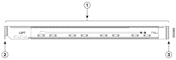
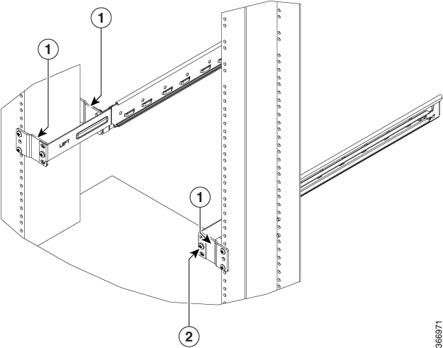
1 |
Mounting depth - Minimum is 547 mm and Maximum is 847 mm |
|
2 |
Front rail mating surface |
|
3 |
Rear rail mating surface |
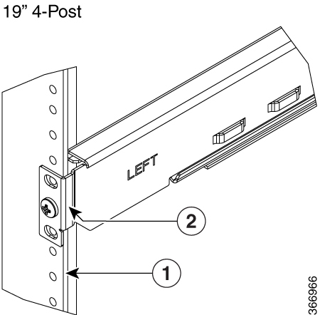
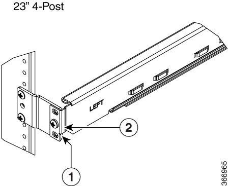
The front and rear vertical rails of four post racks must be within this range (547 to 847 mm) to install NCS 1001. NCS 1001 cannot be installed on a four post rack if the distance between rails is outside this limit.


 Feedback