|
Step 1
|
Download the Cisco Nexus Dashboard image.
-
Browse to the Software Download page.
-
Click Nexus Dashboard Software.
-
From the left sidebar, choose the Nexus Dashboard version you want to download.
-
Download the Cisco Nexus Dashboard image for Linux KVM (nd-dk9.<version>.qcow2).
|
|
Step 2
|
Copy the image to the Linux KVM servers where you will host the nodes.
You can use scp to copy the image, for example:
# scp nd-dk9.<version>.qcow2 root@<kvm-host-ip>:/home/nd-base
The following steps assume you copied the image into the /home/nd-base directory.
|
|
Step 3
|
Create the required disk images for the first node.
You will create a snapshot of the base qcow2 image you downloaded and use the snapshots as the disk images for the nodes' VMs. You will also need to create a second disk
image for each node.
-
Log in to your KVM host as the root user.
-
Create a directory for the node's snapshot.
The following steps assume you create the snapshot in the /home/nd-node1 directory.
# mkdir -p /home/nd-node1/
# cd /home/nd-node1
-
Create the snapshot.
In the following command, replace /home/nd-base/nd-dk9.<version>.qcow2 with the location of the base image you created in the previous step.
# qemu-img create -f qcow2 -b /home/nd-base/nd-dk9.<version>.qcow2 /home/nd-node1/nd-node1-disk1.qcow2
|
Note
|
If you are deploying in RHEL 8.6, you may need to provide an additional parameter to define the destination snapshot's format
as well. In that case, update the above command to the following:
# qemu-img create -f qcow2 -b
                                                            /home/nd-base/nd-dk9.2.1.1a.qcow2
                                                            /home/nd-node1/nd-node1-disk1.qcow2
                                                            -F qcow2
|
-
Create the additional disk image for the node.
Each node requires two disks: a snapshot of the base Nexus Dashboard qcow2 image and a second 500GB disk.
# qemu-img create -f qcow2 /home/nd-node1/nd-node1-disk2.qcow2 500G
|
|
Step 4
|
Repeat the previous step to create the disk images for the second and third nodes.
Before you proceed to the next step, you should have the following:
-
For the first node, /home/nd-node1/ directory with two disk images:
-
/home/nd-node1/nd-node1-disk1.qcow2, which is a snapshot of the base qcow2 image you downloaded in Step 1.
-
/home/nd-node1/nd-node1-disk2.qcow2, which is a new 500GB disk you created.
-
For the second node, /home/nd-node2/ directory with two disk images:
-
/home/nd-node2/nd-node2-disk1.qcow2, which is a snapshot of the base qcow2 image you downloaded in Step 1.
-
/home/nd-node2/nd-node2-disk2.qcow2, which is a new 500GB disk you created.
-
For the tthird node, /home/nd-node3/ directory with two disk images:
-
/home/nd-node1/nd-node3-disk1.qcow2, which is a snapshot of the base qcow2 image you downloaded in Step 1.
-
/home/nd-node1/nd-node3-disk2.qcow2, which is a new 500GB disk you created.
|
|
Step 5
|
Create the first node's VM.
-
Open the KVM console and click New Virtual Machine.
You can open the KVM console from the command line using the virt-manager command.
-
In the New VM screen, choose Import existing disk image option and click Forward.
-
In the Provide existing storage path field, click Browse and select the nd-node1-disk1.qcow2 file.
We recommend that each node's disk image is stored on its own disk partition.
-
Choose Generic for the OS type and Version, then click Forward.
-
Specify 64GB memory and 16 CPUs, then click Forward.
-
Enter the Name of the virtual machine, for example nd-node1 and check the Customize configuration before install option. Then click Finish.
|
Note
|
You must select the Customize configuration before install checkbox to be able to make the disk and network card customizations required for the node.
|
The VM details window will open.
In the VM details window, change the NIC's device model:
-
Select NIC <mac>.
-
For Device model, choose e1000.
-
For Network Source, choose the bridge device and provide the name of the "mgmt" bridge.
In the VM details window, add a second NIC:
-
Click Add Hardware.
-
In the Add New Virtual Hardware screen, select Network.
-
For Network Source, choose the bridge device and provide the name of the created "data" bridge.
-
Leave the default Mac address value.
-
For Device model, choose e1000.
In the VM details window, add the second disk image:
-
Click Add Hardware.
-
In the Add New Virtual Hardware screen, select Storage.
-
For the disk's bus driver, choose IDE.
-
Select Select or create custom storage, click Manage, and select the nd-node1-disk2.qcow2 file you created.
-
Click Finish to add the second disk.
Finally, click Begin Installation to finish creating the node's VM.
|
|
Step 6
|
Repeat previous steps to deploy the second and third nodes, then start all VMs.
|
Note
|
If you are deploying a single-node cluster, you can skip this step.
|
|
|
Step 7
|
Open one of the node's console and configure the node's basic information.
-
Press any key to begin initial setup.
You will be prompted to run the first-time setup utility:
[ OK ] Started atomix-boot-setup.
       Starting Initial cloud-init job (pre-networking)...
       Starting logrotate...
       Starting logwatch...
       Starting keyhole...
[ OK ] Started keyhole.
[ OK ] Started logrotate.
[ OK ] Started logwatch.

Press any key to run first-boot setup on this console...
-
Enter and confirm the admin password
This password will be used for the rescue-user SSH login as well as the initial GUI password.
|
Note
|
You must provide the same password for all nodes or the cluster creation will fail.
|
Admin Password:
Reenter Admin Password:
-
Enter the management network information.
Management Network:
  IP Address/Mask: 192.168.9.172/24
  Gateway: 192.168.9.1
-
For the first node only, designate it as the "Cluster Leader".
You will log into the cluster leader node to finish configuration and complete cluster creation.
Is this the cluster leader?: y
-
Review and confirm the entered information.
You will be asked if you want to change the entered information. If all the fields are correct, choose n to proceed. If you want to change any of the entered information, enter y to re-start the basic configuration script.
Please review the config
Management network:
  Gateway: 192.168.9.1
  IP Address/Mask: 192.168.9.172/24
Cluster leader: yes

Re-enter config? (y/N): n
|
|
Step 8
|
Repeat previous step to configure the initial information for the second and third nodes.
You do not need to wait for the first node configuration to complete, you can begin configuring the other two nodes simultaneously.
|
Note
|
You must provide the same password for all nodes or the cluster creation will fail.
The steps to deploy the second and third nodes are identical with the only exception being that you must indicate that they
are not the Cluster Leader.
|
|
|
Step 9
|
Wait for the initial bootstrap process to complete on all nodes.
After you provide and confirm management network information, the initial setup on the first node (Cluster Leader) configures the networking and brings up the UI, which you will use to add two other nodes and complete the cluster deployment.
Please wait for system to boot: [#########################] 100%
System up, please wait for UI to be online.

System UI online, please login to https://192.168.9.172 to continue.
|
|
Step 10
|
Open your browser and navigate to https://<node-mgmt-ip> to open the GUI.
The rest of the configuration workflow takes place from one of the node's GUI. You can choose any one of the nodes you deployed
to begin the bootstrap process and you do not need to log in to or configure the other two nodes directly.
Enter the password you provided in a previous step and click Login 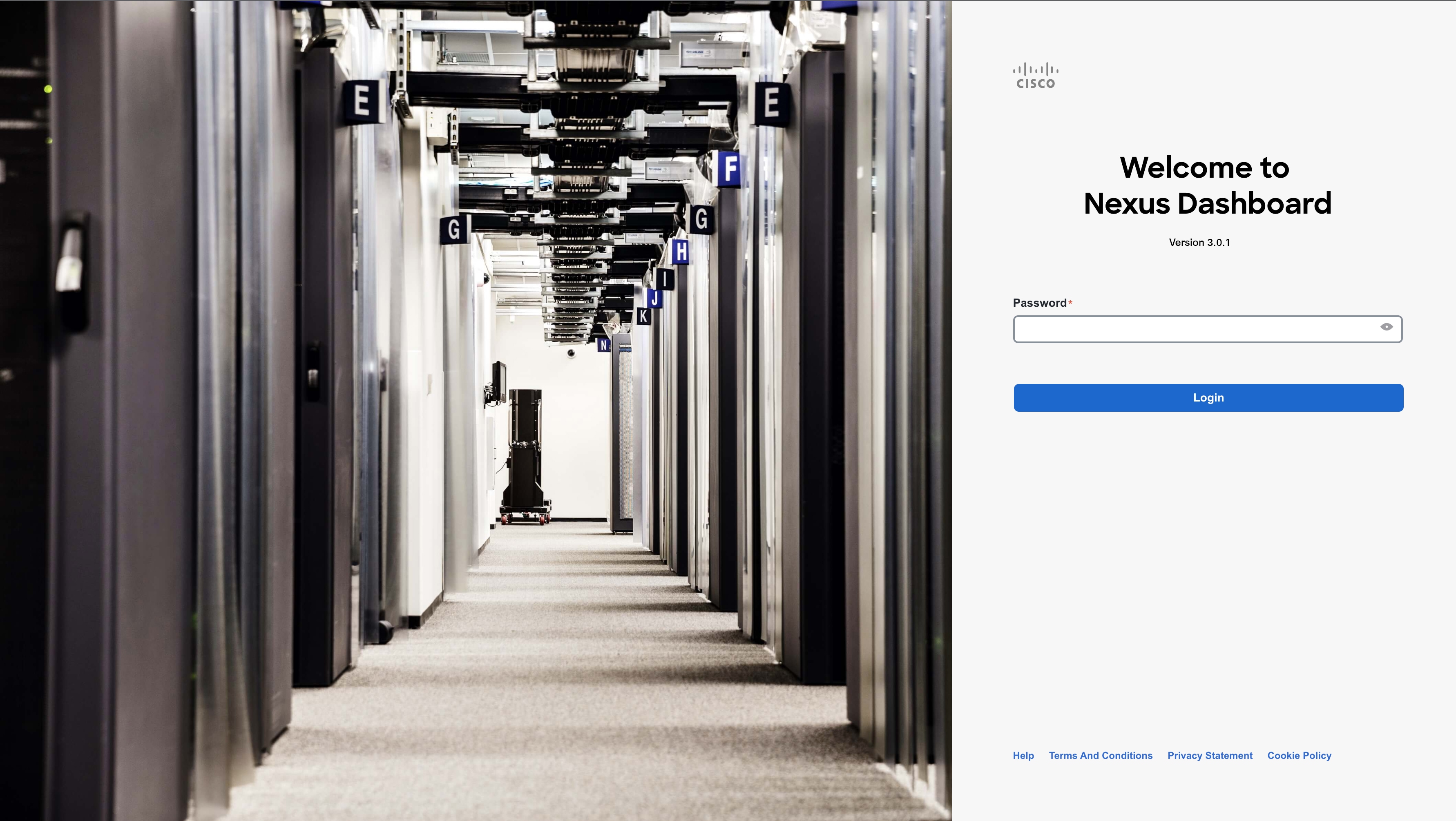
|
|
Step 11
|
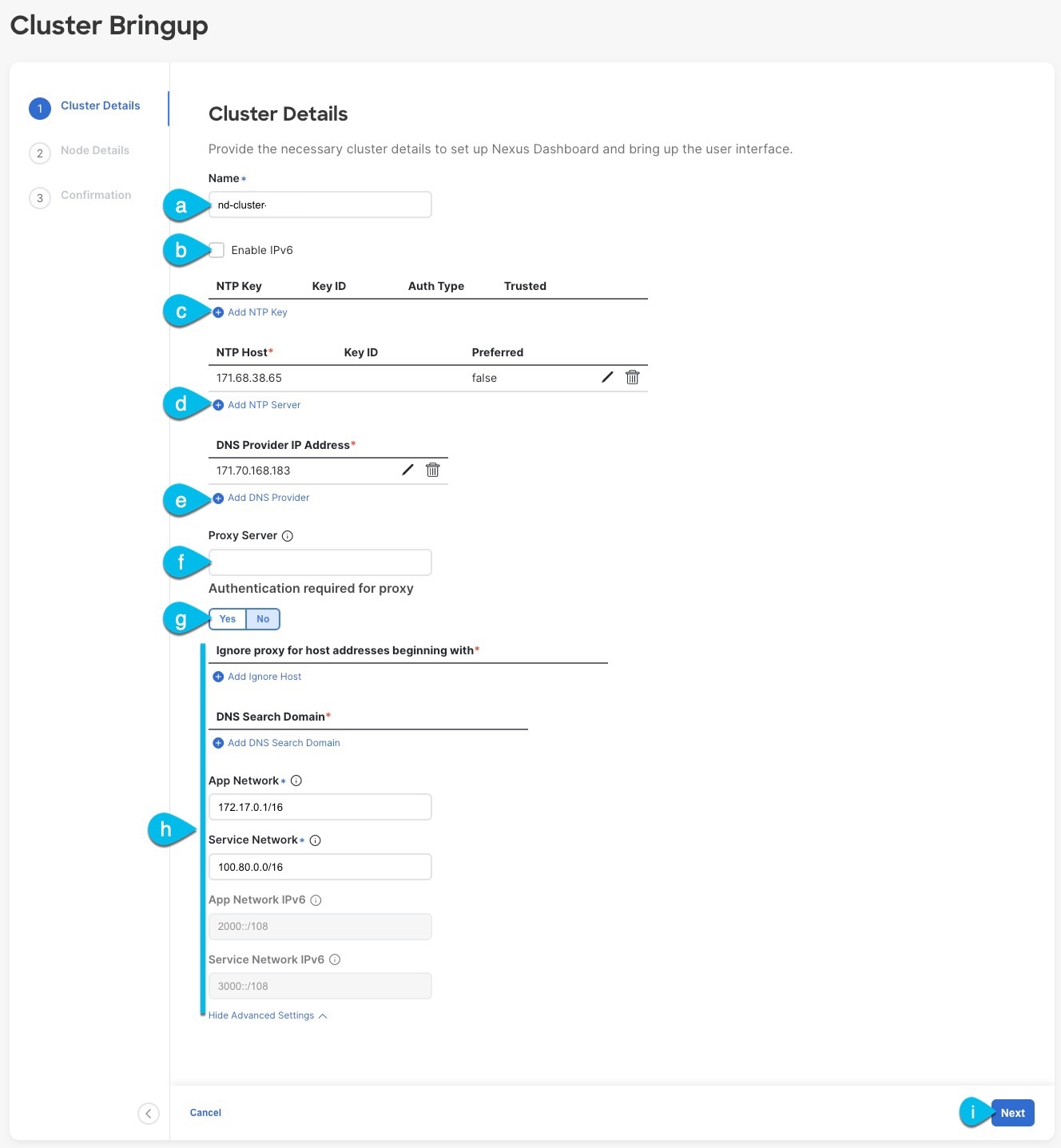
Provide the Cluster Details.
In the Cluster Details screen of the Cluster Bringup wizard, provide the following information:
-
Provide the Cluster Name for this Nexus Dashboard cluster.
The cluster name must follow the RFC-1123 requirements.
-
(Optional) If you want to enable IPv6 functionality for the cluster, check the Enable IPv6 checkbox.
-
(Optional) If you want to enable NTP server authentication, click Add NTP Key.
In the additional fields, provide the following information:
-
NTP Key – a cryptographic key that is used to authenticate the NTP traffic between the Nexus Dashboard and the NTP server(s). You
will define the NTP servers in the following step, and multiple NTP servers can use the same NTP key.
-
Key ID – each NTP key must be assigned a unique key ID, which is used to identify the appropriate key to use when verifying the
NTP packet.
-
Auth Type – this release supports MD5, SHA, and AES128CMAC authentication types.
-
Choose whether this key is Trusted. Untrusted keys cannot be used for NTP authentication.
After you've entered the information, click the checkmark icon to save it.
-
Click +Add NTP Host to add one or more NTP servers.
In the additional fields, provide the following information:
-
NTP Host – you must provide an IP address; fully qualified domain name (FQDN) are not supported.
-
Key ID – if you want to enable NTP authentication for this server, provide the key ID of the NTP key you defined in the previous
step.
-
Choose whether this NTP server is Preferred.
After you've entered the information, click the checkmark icon to save it.
|
Note
|
If the node into which you are logged in is configured with only an IPv4 address, but you have checked Enable IPv6 in a previous step and provided an IPv6 address for an NTP server, you will get the following validation error:
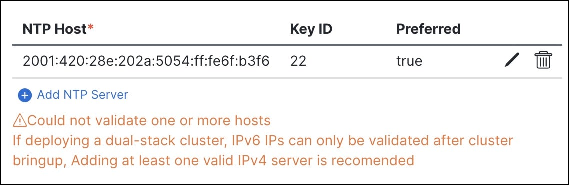 This is because the node does not have an IPv6 address yet (you will provide it in the next step) and is unable to connect
to an IPv6 address of the NTP server.
In this case, simply finish providing the other required information as described in the following steps and click Next to proceed to the next screen where you will provide IPv6 addresses for the nodes.
|
If you want to provide additional NTP servers, click +Add NTP Host again and repeat this substep.
-
Click +Add DNS Provider to add one or more DNS servers.
After you've entered the information, click the checkmark icon to save it.
-
Provide a Proxy Server.
For clusters that do not have direct connectivity to Cisco cloud, we recommend configuring a proxy server to establish the
connectivity. This allows you to mitigate risk from exposure to non-conformant hardware and software in your fabrics.
The proxy server must have the following URLs enabled:
dcappcenter.cisco.com
svc.intersight.com
svc.ucs-connect.com
svc-static1.intersight.com
svc-static1.ucs-connect.com
If you want to skip proxy configuration, mouse over the information (i) icon next to the field, then click Skip.
-
(Optional) If your proxy server required authentication, change Authentication required for Proxy to Yes and provide the login credentials.
-
(Optional) Expand the Advanced Settings category and change the settings if required.
Under advanced settings, you can configure the following:
-
Provide one or more search domains by clicking +Add DNS Search Domain.
After you've entered the information, click the checkmark icon to save it.
-
Provide custom App Network and Service Network.
The application overlay network defines the address space used by the application's services running in the Nexus Dashboard.
The field is pre-populated with the default 172.17.0.1/16 value.
The services network is an internal network used by the Nexus Dashboard and its processes. The field is pre-populated with
the default 100.80.0.0/16 value.
If you have checked the Enable IPv6 option earlier, you can also define the IPv6 subnets for the App and Service networks.
Application and Services networks are described in the Prerequisites and Guidelines section earlier in this document.
-
Click Next to continue.
|
Note
|
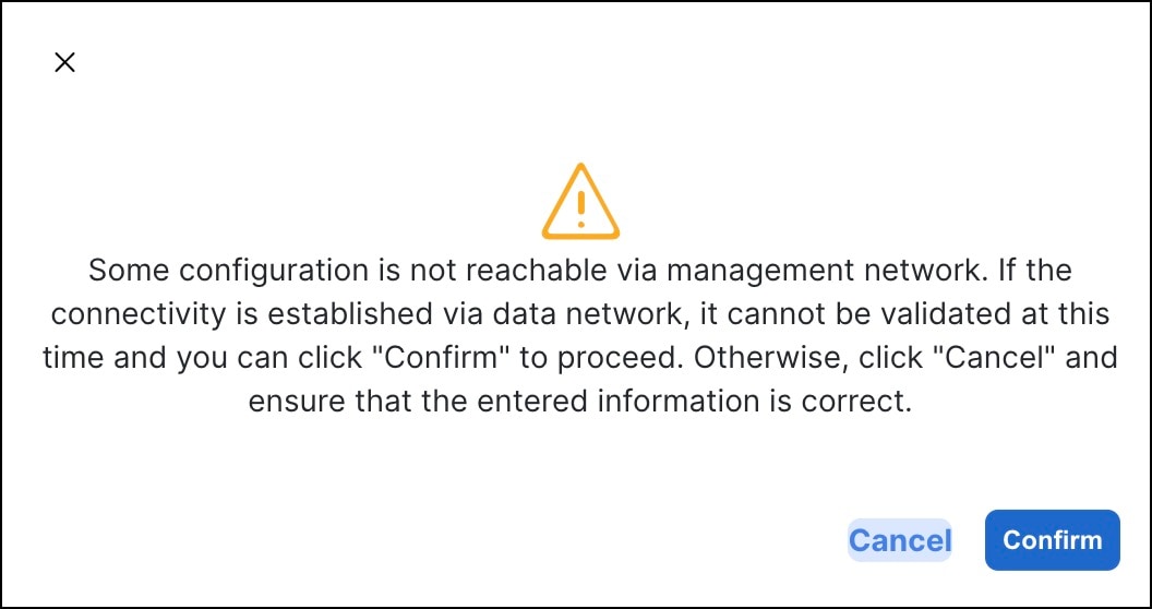
If your node has only an IPv4 management address but you have checked Enabled IPv6 and provided an IPv6 NTP server address, ensure that the NTP address is correct and click Confirm to proceed to the next screen where you will provide the nodes' IPv6 addresses.
|
|
|
Step 12
|
In the Node Details screen, update the current node's information.
You have defined the Management network and IP address for the node into which you are currently logged in during the initial
node configuration in earlier steps, but you must also provide the Data network information for the node before you can proceed
with adding the other primary nodes and creating the cluster.
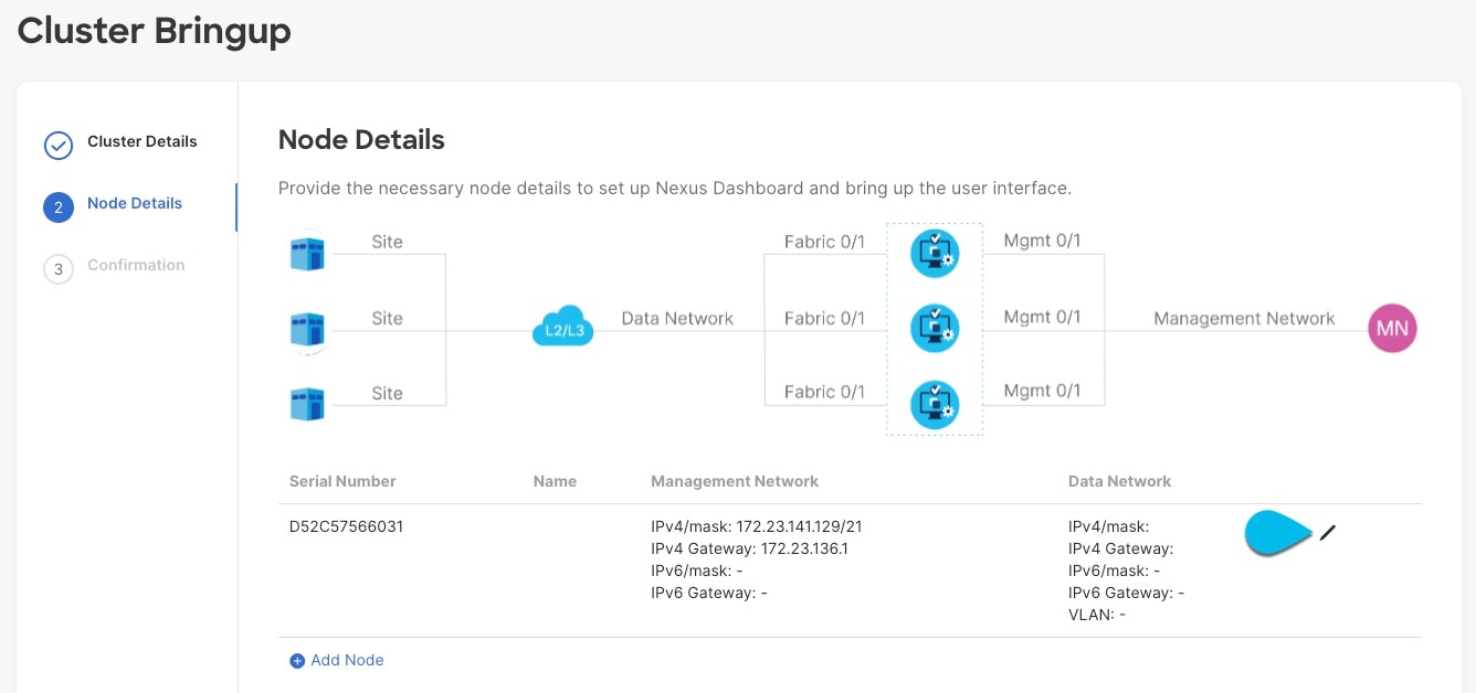
-
Click the Edit button next to the first node.
-
Provide the Name for the node.
The node's Serial Number and the Management Network information are automatically populated.
The node's Name will be set as its hostname, so it must follow the RFC-1123 requirements.
-
In the Data Network area, provide the node's Data Network information.
You must provide the data network IP address, netmask, and gateway. Optionally, you can also provide the VLAN ID for the network.
For most deployments, you can leave the VLAN ID field blank.
If you had enabled IPv6 functionality in a previous screen, provide the IPv6 address, netmask, and gateway.
|
Note
|
If you want to provide IPv6 information, you must do it during cluster bootstrap process. To change IP configuration later,
you would need to redeploy the cluster.
All nodes in the cluster must be configured with either only IPv4, only IPv6, or dual IPv4/IPv6 stack.
|
-
(Optional) If required, Enable BGP for the data network.
BGP configuration is required for the Persistent IPs feature used by some services, such as Nexus Dashboard Insights with
NDFC fabrics. This feature is described in more detail in Prerequisites and Guidelines and the "Persistent IP Addresses" sections of the Cisco Nexus Dashboard User Guide.
|
Note
|
You can enable BGP at this time or in the Nexus Dashboard GUI after the cluster is deployed.
|
When you enable BGP, you must also provide the following information:
-
ASN (BGP Autonomous System Number) of this node.
You can configure the same ASN for all nodes or a different ASN per node.
-
For pure IPv6, the Router ID of this node.
The router ID must be an IPv4 address, for example 1.1.1.1
-
BGP Peer Details, which includes the peer's IPv4 or IPv6 address and peer's ASN.
-
Click Update to save the changes.
|
|
Step 13
|
In the Node Details screen, click Add Node to add the second node to the cluster.
If you are deploying a single-node cluster, skip this step. 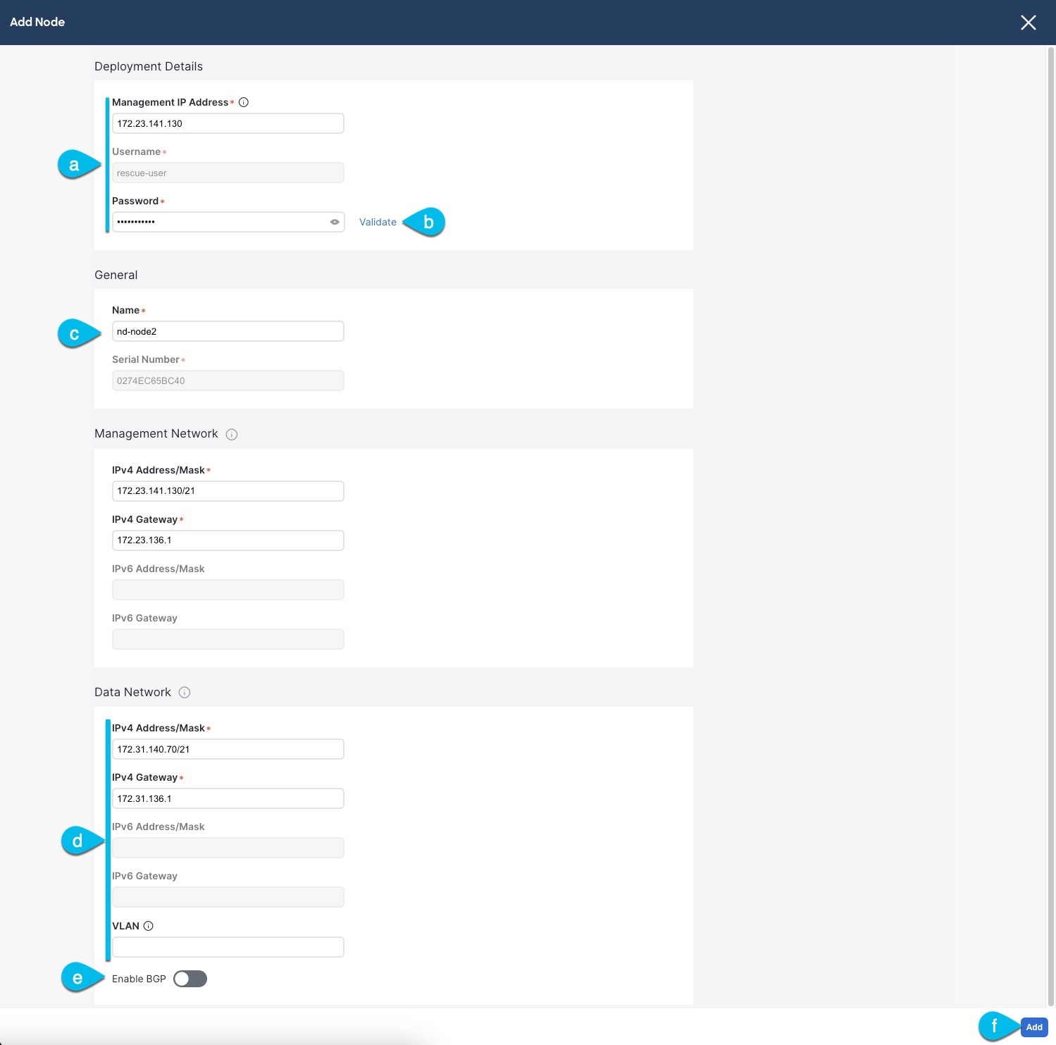
-
In the Deployment Details area, provide the Management IP Address and Password for the second node
You defined the management network information and the password during the initial node configuration steps.
-
Click Validate to verify connectivity to the node.
After network connectivity is validated, you can provide the other required information for the node.
-
Provide the Name for the node.
The node's Serial Number and the Management Network information are automatically populated during the management network information validation in the previous step.
-
In the Data Network area, provide the node's Data Network information.
You must provide the data network IP address, netmask, and gateway. Optionally, you can also provide the VLAN ID for the network.
For most deployments, you can leave the VLAN ID field blank.
If you had enabled IPv6 functionality in a previous screen, provide the IPv6 address, netmask, and gateway.
|
Note
|
If you want to provide IPv6 information, you must do it during cluster bootstrap process. To change IP configuration later,
you would need to redeploy the cluster.
All nodes in the cluster must be configured with either only IPv4, only IPv6, or dual IPv4/IPv6 stack.
|
-
(Optional) If required, Enable BGP for the data network.
BGP configuration is required for the Persistent IPs feature used by some services, such as Nexus Dashboard Insights with
NDFC fabrics. This feature is described in more detail in Prerequisites and Guidelines and the "Persistent IP Addresses" sections of the Cisco Nexus Dashboard User Guide.
|
Note
|
You can enable BGP at this time or in the Nexus Dashboard GUI after the cluster is deployed.
|
When you enable BGP, you must also provide the following information:
-
ASN (BGP Autonomous System Number) of this node.
You can configure the same ASN for all nodes or a different ASN per node.
-
For pure IPv6, the Router ID of this node.
The router ID must be an IPv4 address, for example 2.2.2.2
-
BGP Peer Details, which includes the peer's IPv4 or IPv6 address and peer's ASN.
-
Click Add to save the changes.
|
|
Step 14
|
Repeat the previous step to add the 3rd node.
If you are deploying a single-node cluster, skip this step.
|
|
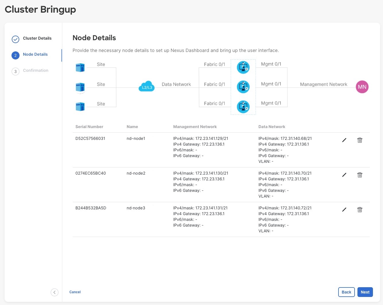
Step 15
|
In the Node Details page, click Next to continue.
After you have provided the management and data network information for all nodes, you can proceed to the final Confirmation screen.
|
|
Step 16
|
In the Confirmation screen, review and verify the configuration information and click Configure to create the cluster.
During the node bootstrap and cluster bring-up, the overall progress as well as each node's individual progress will be displayed
in the UI. If you do not see the bootstrap progress advance, manually refresh the page in your browser to update the status.
It may take up to 30 minutes for the cluster to form and all the services to start. When cluster configuration is complete,
the page will reload to the Nexus Dashboard GUI.
|
|
Step 17
|
Verify that the cluster is healthy.
It may take up to 30 minutes for the cluster to form and all the services to start.
After all three nodes are ready, you can log in to any one node via SSH as the rescue-user using the password you provided during node deployment and run the following command to verify cluster health:
-
Verify that the cluster is up and running.
You can check the current status of cluster deployment by logging in to any of the nodes and running the acs health command.
While the cluster is converging, you may see the following outputs: $ acs health
k8s install is in-progress
$ acs health
k8s services not in desired state - [...]
$ acs health
k8s: Etcd cluster is not ready
When the cluster is up and running, the following output will be displayed:$ acs health
All components are healthy
-
Log in to the Nexus Dashboard GUI.
After the cluster becomes available, you can access it by browsing to any one of your nodes' management IP addresses. The
default password for the admin user is the same as the rescue-user password you chose for the first node of the Nexus Dashboard cluster.
|

 Feedback