Prerequisites and Guidelines
Before you proceed with deploying the Nexus Dashboard cluster in VMware ESX, you must:
-
Ensure that the ESX form factor supports your scale and services requirements.
Scale and services support and co-hosting vary based on the cluster form factor and the specific services you plan to deploy. You can use the Nexus Dashboard Capacity Planning tool to verify that the virtual form factor satisfies your deployment requirements.

Note
This document describes how to initially deploy the base Cisco Nexus Dashboard cluster. If you want to expand an existing cluster with additional
workernodes, see the Infrastructure Management article instead, which is also available from the Cisco Nexus Dashboard UI.Some services (such as Nexus Dashboard Fabric Controller) may require only a single ESX virtual node for one or more specific use cases. In that case, the capacity planning tool will indicate the requirement and you can simply skip the additional node deployment step in the following sections.
Standby nodes are not supported with this cluster form factor.
-
Review and complete the general prerequisites described in Deployment Overview and Requirements.
Note that this document describes how to initially deploy the base Nexus Dashboard cluster. If you want to expand an existing cluster with additional nodes (such as
workerorstandby), see the "Infrastructure Management" chapter of the Cisco Nexus Dashboard User Guide instead, which is available from the Nexus Dashboard UI or online at Cisco Nexus Dashboard User Guide -
Review and complete any additional prerequisites described in the Release Notes for the services you plan to deploy.
-
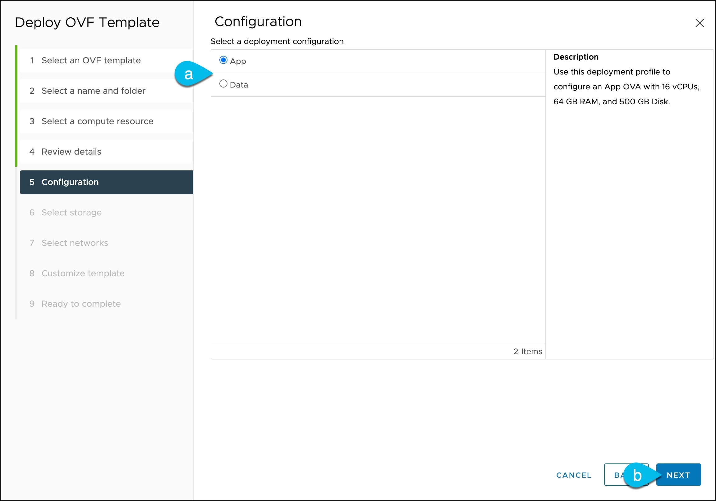
When deploying in VMware ESX, you can deploy two types of nodes:
-
Data Node—node profile with higher system requirements designed for specific services that require the additional resources.
-
App Node—node profile with a smaller resource footprint that can be used for most services.
Note
Some larger scale Nexus Dashboard Fabric Controller deployments may require additional worker nodes. If you plan to add worker nodes to your NDFC cluster, you can deploy all nodes (the initial 3-node cluster and the additional worker nodes) using the OVA-App profile. Detailed scale information is available in the Verified Scalability Guide for Cisco Nexus Dashboard Fabric Controller for your release.
Ensure you have enough system resources:
Table 1. Deployment Requirements Data Node Requirements
App Node Requirements
-
VMware ESXi 7.0, 7.0.1, 7.0.2, 7.0.3
-
VMware vCenter 7.0.1, 7.0.2, 7.0.3 if deploying using vCenter
-
Each VM requires the following:
-
32 vCPUs with physical reservation of at least 2.2GHz
-
128GB of RAM with physical reservation
-
3TB SSD storage for the data volume and an additional 50GB for the system volume
Datanodes must be deployed on storage with the following minimum performance requirements:-
The SSD must be attached to the data store directly or in JBOD mode if using a RAID Host Bus Adapter (HBA)
-
The SSDs must be optimized for
Mixed Use/Application(notRead-Optimized) -
4K Random Read IOPS:
93000 -
4K Random Write IOPS:
31000
-
-
-
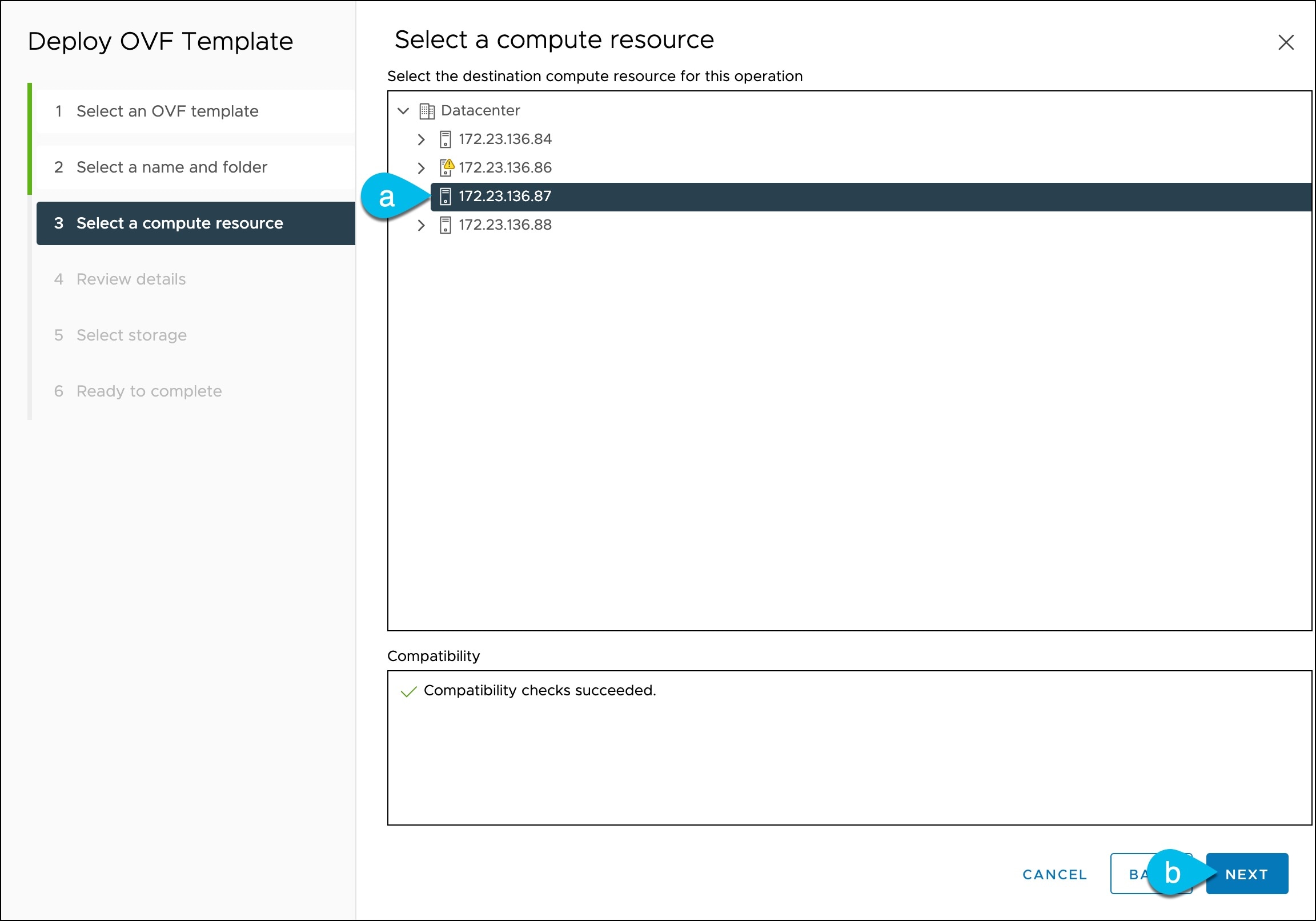
We recommend that each Nexus Dashboard node is deployed in a different ESXi server.
-
VMware ESXi 7.0, 7.0.1, 7.0.2, 7.0.3
-
VMware vCenter 7.0.1, 7.0.2, 7.0.3 if deploying using vCenter
-
Each VM requires the following:
-
16 vCPUs with physical reservation of at least 2.2GHz
-
64GB of RAM with physical reservation
-
500GB HDD or SSD storage for the data volume and an additional 50GB for the system volume
Some services require
Appnodes to be deployed on faster SSD storage while other services support HDD. Check the Nexus Dashboard Capacity Planning tool to ensure that you use the correct type of storage.Note
Beginning with Nexus Dashboard release 3.0(1i) and Nexus Dashboard Insights release 6.3(1), you can use the OVA-App node profile for the Insights service. However, you must change from the default 500GB disk requirement to 1536GB when deploying node VMs which will be used for hosting Insights.
-
-
We recommend that each Nexus Dashboard node is deployed in a different ESXi server.
-
-
If you plan to configure VLAN ID for the cluster nodes' data interfaces, you must enable VLAN 4095 on the data interface port group in vCenter for Virtual Guest VLAN Tagging (VGT) mode.
If you specify a VLAN ID for Nexus Dashboard data interfaces, the packets must carry a Dot1q tag with that VLAN ID. When you set an explicit VLAN tag in a port group in the vSwitch and attach it to a Nexus Dashboard VM's VNIC, the vSwitch removes the Dot1q tag from the packet coming from the uplink before it sends the packet to that VNIC. Because the vND node expects the Dot1q tag, you must enable VLAN 4095 on the data interface port group to allow all VLANs.
-
After each node's VM is deployed, ensure that the VMware Tools' periodic time synchronization is disabled as described in the deployment procedure in the next section.
-
VMware vMotion is not supported for Nexus Dashboard cluster nodes.
-
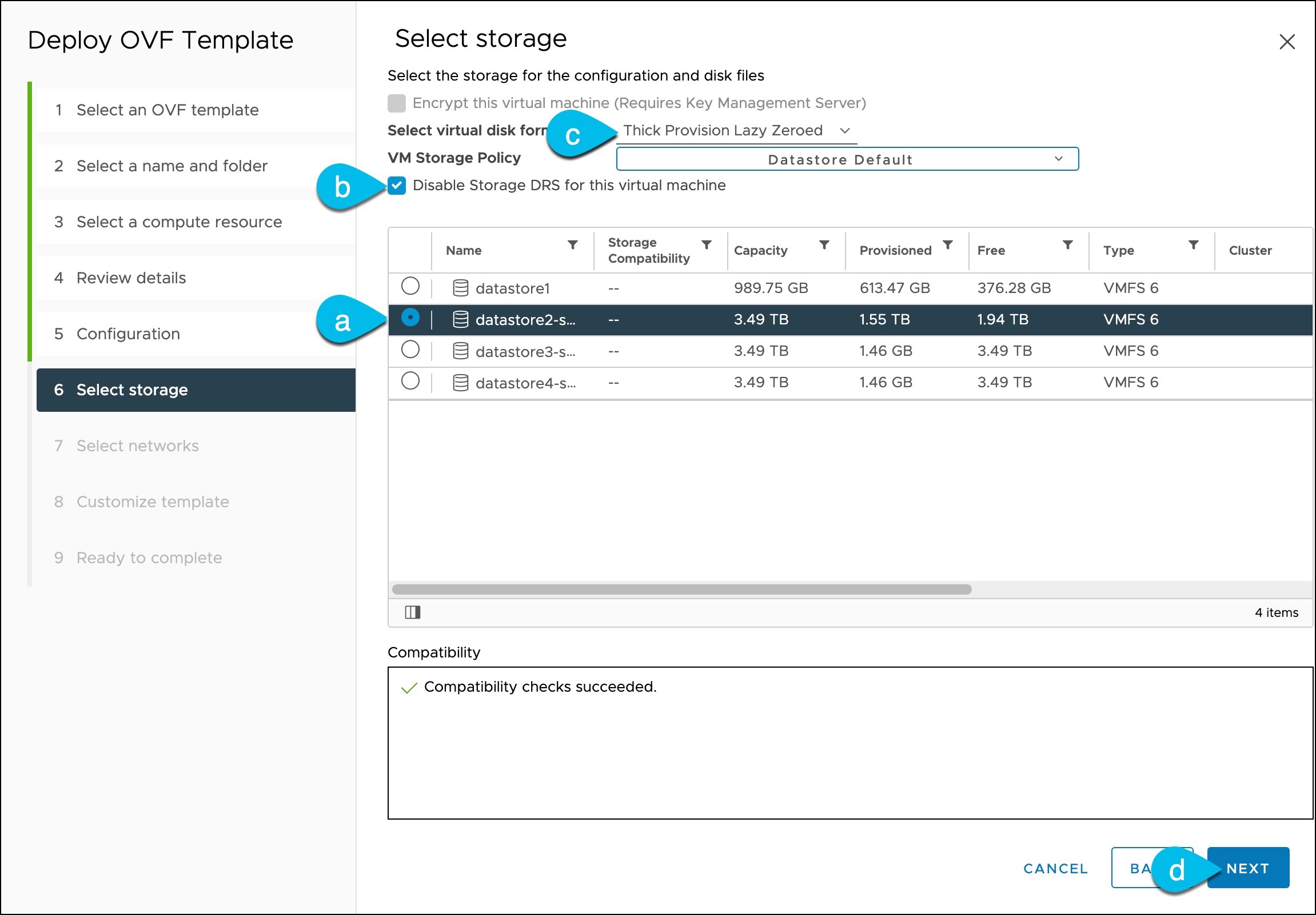
VMware Distributed Resource Scheduler (DRS) is not supported for Nexus Dashboard cluster nodes.
If you have DRS enabled at the ESXi cluster level, you must explicitly disable it for the Nexus Dashboard VMs during deployment as described in the following section.
-
Because Nexus Dashboard is a platform infrastructure, it is not possible to bring down all services.
In other words, if you want to take a snapshot of the virtual machine (such as for debugging purposes), the snapshot must have all Nexus Dashboard services running.
-
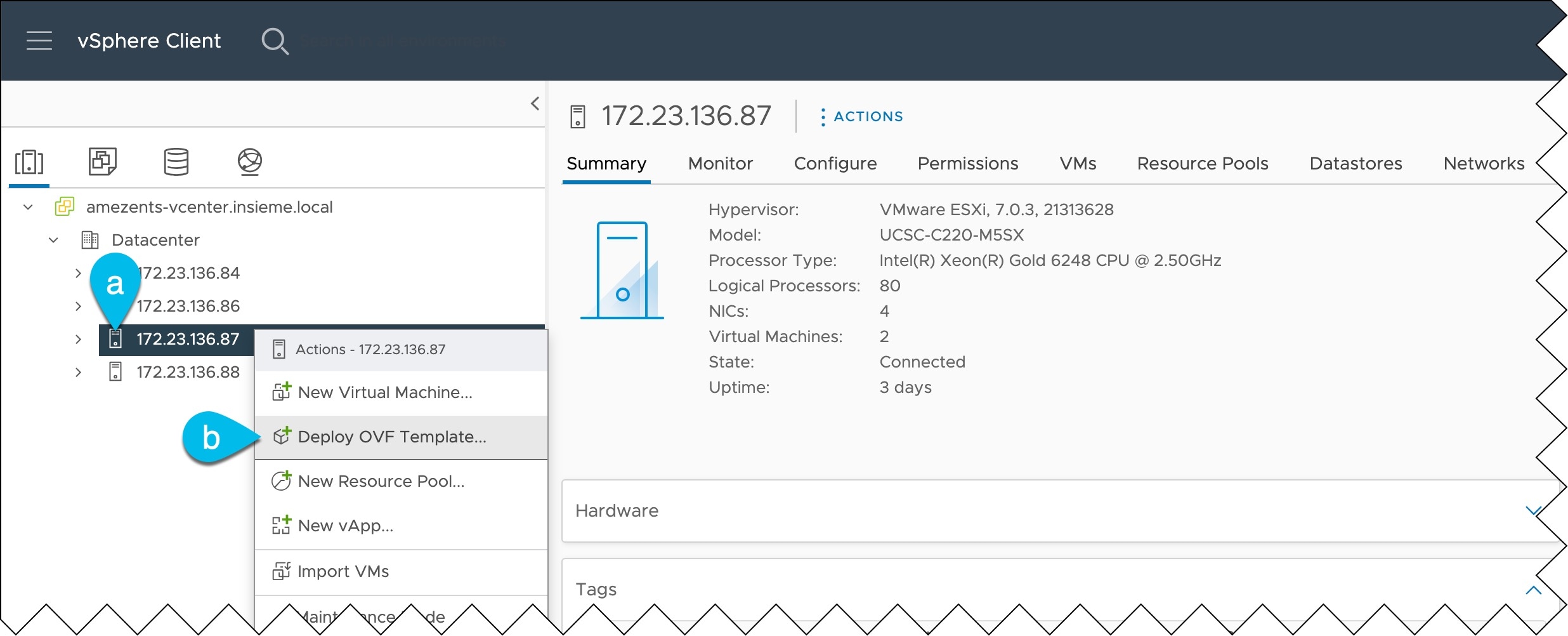
You can choose to deploy the nodes directly in ESXi or using vCenter.
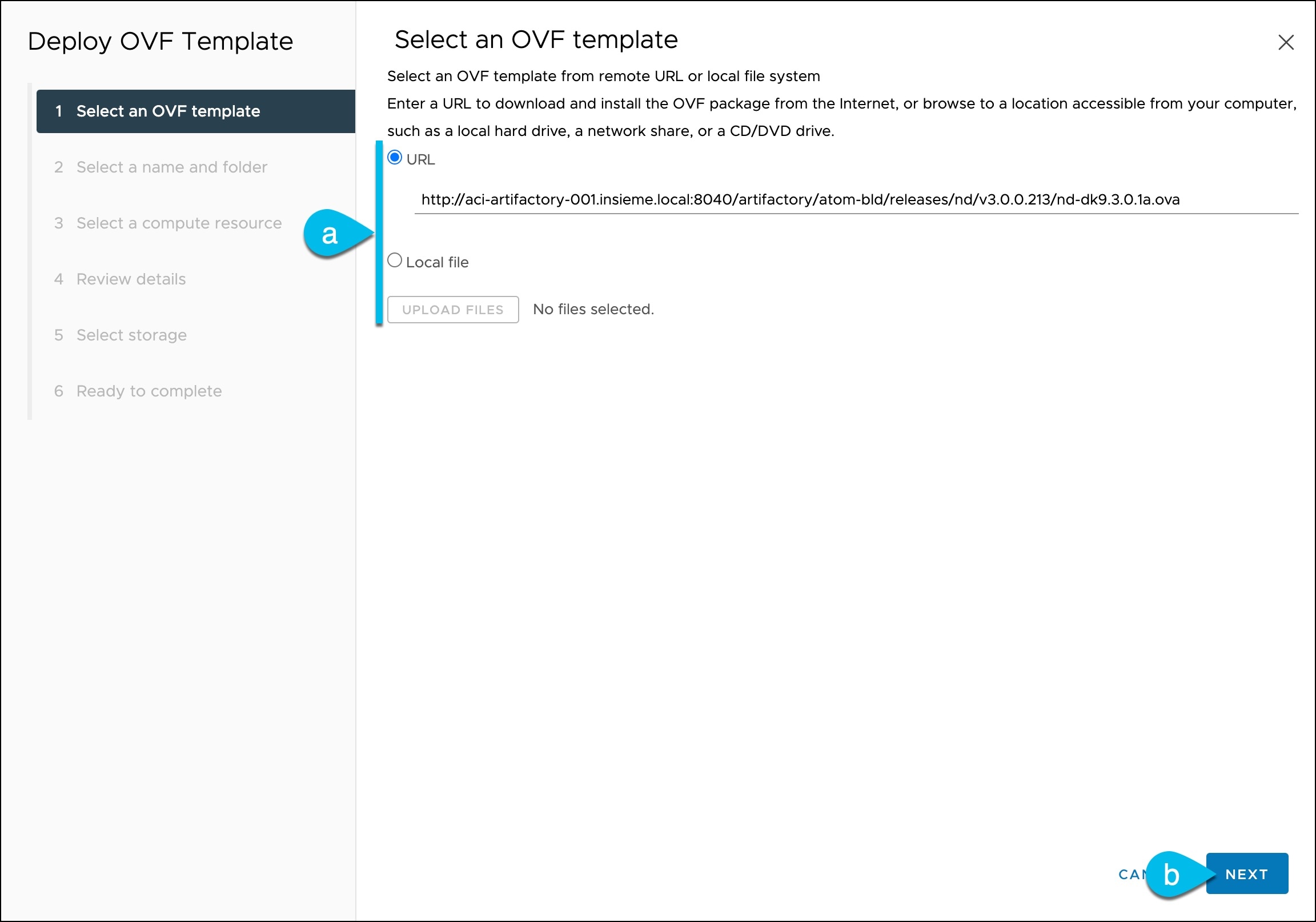
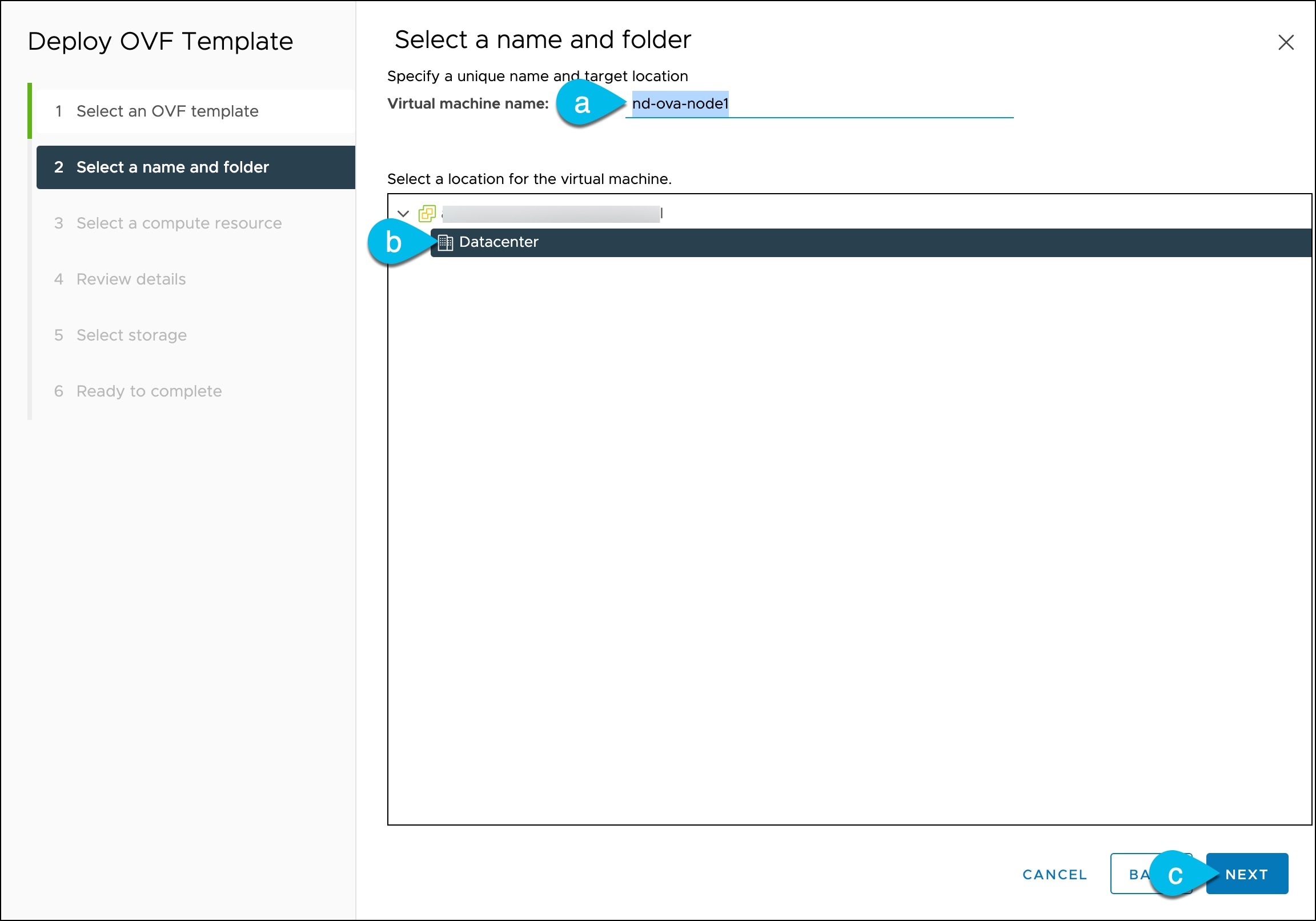
If you want to deploy using vCenter, following the steps described in Deploying Nexus Dashboard Using VMware vCenter.
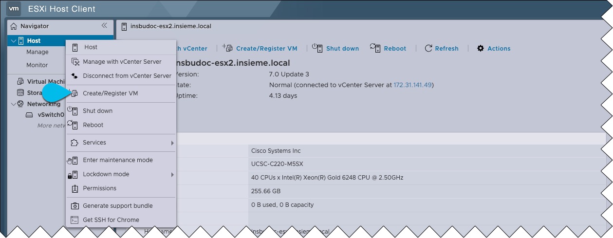
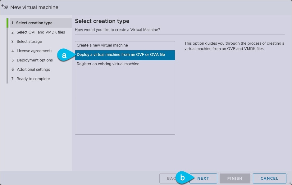
If you want to deploy directly in ESXi, following the steps described in Deploying Nexus Dashboard Directly in VMware ESXi.
Note
If you plan to deploy Nexus Dashboard Insights using the OVA-App node profile, you must deploy using vCenter.
Nexus Dashboard Insights requires a larger disk size than the default value for OVA-App node profiles. If you plan to deploy NDI using the OVA-App node profile, you must change the default disk size for OVA-App nodes from 500GB to 1.5TB during VM deployment. Disk size customization is supported when deploying through VMware vCenter only. For detailed Insights requirements, see the Nexus Dashboard Capacity Planning and the Nexus Dashboard Insights Deployment document.

 Feedback