Features
The Cisco Provider Connectivity Assurance Module Dock (formerly Skylight module dock) is a quick and clientless way to pre-stage both the Cisco Provider Connectivity Assurance Sensor SFP (formerly Skylight sensor: SFP compute) and Cisco Provider Connectivity Assurance Sensor Modules (formerly Skylight sensor: module). Certain network topologies and operational workflows may favor preconfiguring modules such as the Sensor SFP and Sensor Modules to facilitate the discovery and control by the Cisco Provider Connectivity Assurance (formerly Accedian Skylight) Performance Platform. The Module Dock is a USB-powered configuration tool that connects to modules through its RJ45 or SFP port. Upon connection, the Module Dock uses secure authentication to ensure that only genuine Module Docks can communicate with the module. Once the necessary security keys have been exchanged, module configuration and firmware can be updated.

The following table lists the features for the Module Dock.
|
Feature |
Description |
|---|---|
|
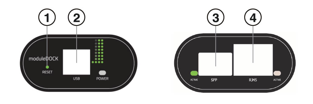
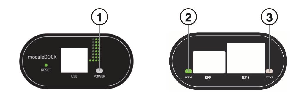
RJ-45 port |
One RJ-45 connector for Sensor Modules (using an Ethernet cable) |
|
SFP port |
One SFP connect for Sensor SFP |
|
USB 2.0 port |
One USB connector for host computer (using a USB cable) |
 Feedback