The documentation set for this product strives to use bias-free language. For the purposes of this documentation set, bias-free is defined as language that does not imply discrimination based on age, disability, gender, racial identity, ethnic identity, sexual orientation, socioeconomic status, and intersectionality. Exceptions may be present in the documentation due to language that is hardcoded in the user interfaces of the product software, language used based on RFP documentation, or language that is used by a referenced third-party product. Learn more about how Cisco is using Inclusive Language.
This section describes how to use the Cisco iNode Manager application:
Cisco iNode Manager Application
The Cisco iNode Manager application page provides you options to add, organize, and update information about the iNodes in
the network.
The Cable iNode Manager page has five tabs:
Overview
Config Profiles
Node Config
Alarms
System
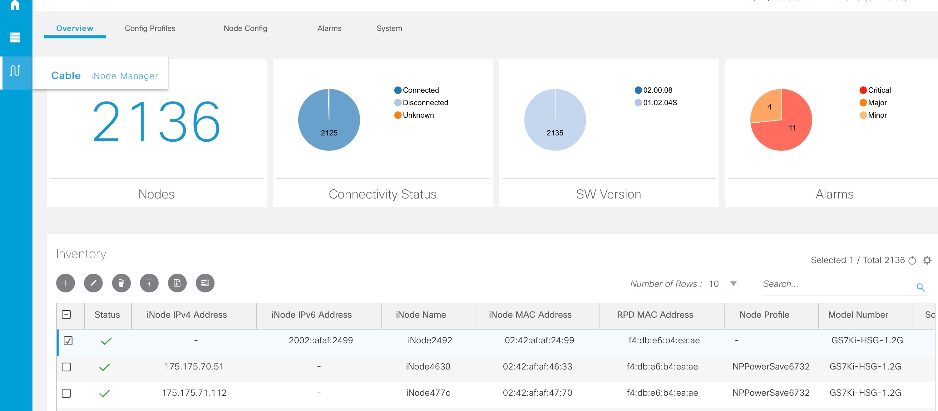
Overview
The Overview page provides the total number of iNodes, their connectivity status, software version running on them, and the number of
active alarms. It also has an Inventory table which shows details of all iNodes in the network. You can perform the following tasks on this page:
Add a new iNode to the inventory
Update the name of the iNode in the inventory
Delete iNodes from the inventory
Export the iNode details from the inventory table in the CSV format
Download log files that are in the iNode, view the latest logs, and the boot parameters of an iNode
Perform bulk operations: Initial setup in bulk, assign configuration profiles, and bulk reboot
The following table contains the descriptions of the graphs on the Overview page and the fields in the inventory table:
Name
Description
Nodes
Total number of iNodes in the inventory.
Connectivity Status
Shows a pie chart of the connectivity status of the iNodes in the network. The following statuses are displayed:
Connected
Disconnected
Unknown
SW Version
Shows a pie chart of the number of iNodes running different software versions.
Alarms
Shows a pie chart of the number of active alarms in the iNodes in the network. The following categories are displayed:
Critical
Major
Minor
Inventory Table Fields
Status
Current Status of the iNode.
iNode IPv4 Address
IPv4 address of the iNode.
A hyphen (-) indicates that the iNode does not have an IPv4 address.
iNode IPv6 Address
IPv6 Address of the iNode.
A hyphen (-) indicates that the iNode does not have an IPv6 Address.
iNode Name
Name of the iNode.
iNode MAC Address
MAC address of the iNode.
RPD MAC Address
MAC address of the RPD that is connected to the iNode.
Node Profile
Name of the Configuration Profile that is assigned to the iNode.
Model Number
Model number of the iNode.
Software Version
Software version of the iNode.
Safe Image Version
Software version of the secondary image in the iNode.
Serial Number
Serial number of the iNode.
RPD IPv4 Address
IPv4 address of the RPD that is connected to the iNode.
RPD IPv6 Address
IPv6 address of the RPD that is connected to the iNode.
RPD Serial Number
Serial number of the RPD that is connected to the iNode.
RPD Software Version
Software version of the RPD that is connected to the iNode.
Adds an iNode to the inventory.
Updates the iNode information.
Deletes iNodes from the inventory.
Exports iNode details to a CSV file.
Downloads the iNode’s logs.
Perform bulk operations.
Sets the columns in the inventory table.
Search
Allows you to search for iNodes based on the search criteria.
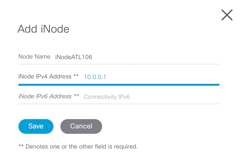
Add an iNode to Inventory
Procedure
Step 1
Log into the Cisco iNode Manager application, and click Dashboard > Launch or choose Cable iNode Manager > Overview.
Step 2
Click the icon to add a node to the Inventory.
The Add iNode pop-up window appears.
Step 3
Enter the IPv4 address or the IPv6 address of the iNode and click Save.
The Cisco iNode Manager retrieves the rest of the details of the iNode, such as the name, MAC address, software version, serial
number, and so on from the iNode and stores it in the inventory.
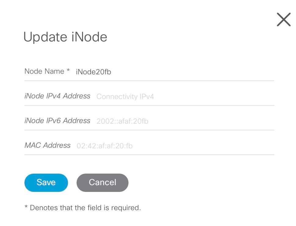
Update the iNode Name
You can update only the name of an iNode.
Procedure
Step 1
Log into the Cisco iNode Manager application, and click Dashboard > Launch or choose Cable iNode Manager > Overview.
Step 2
In the Inventory table, check the check box of the iNode which you want to update.
Step 3
Click the icon to update the name of the iNode.
The Update iNode pop-up window appears.
Step 4
Update the node name and click Save.
Delete iNode from Inventory
You can delete multiple iNodes from the Inventory.
Procedure
Step 1
Log into the Cisco iNode Manager application, and click Dashboard > Launch or choose Cable iNode Manager > Overview.
Step 2
Select the iNodes from the Inventory table and click the icon.
A confirmation message appears.
Step 3
Click Delete to confirm.
Export the Inventory
You can export the details of all iNodes listed in the Inventory in the CSV format.
Procedure
Step 1
Log into the iNode Manager application, and click Dashboard > Launch or choose Cable iNode Manager > Overview.
Step 2
In the Inventory table, check the check boxes for the iNodes of which you want the details exported in a CSV file.
Step 3
Click the icon to export iNodes in the inventory.
A request message to allow downloads appears. This request appears only once for a user profile.
Step 4
Click Allow.
The CSV file is saved to your downloads location on your device. The file name is in the following format: inodeInventoryData-yyyy-mm-dd.hhmmss
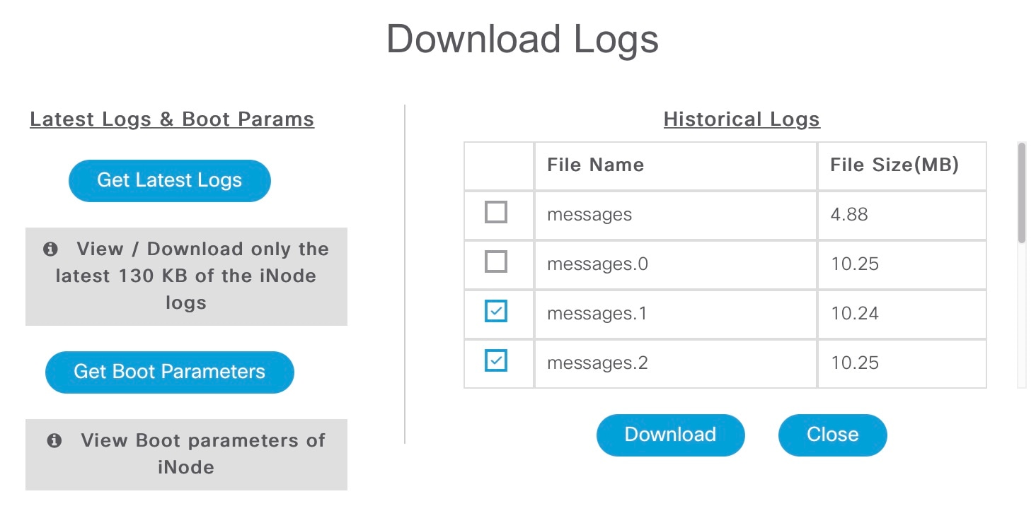
Download Logs
You can view and download the logs to your device.
Procedure
Step 1
Log into the iNode Manager application, and click Dashboard > Launch or choose Cable iNode Manager > Overview.
Step 2
Check the check boxes for the iNodes of which you want to download the logs.
Step 3
Click the icon to view the download options.
The Download Logs pop-up window appears.
Step 4
Click the option based on your requirement.
Option
Description
Get Latest Logs
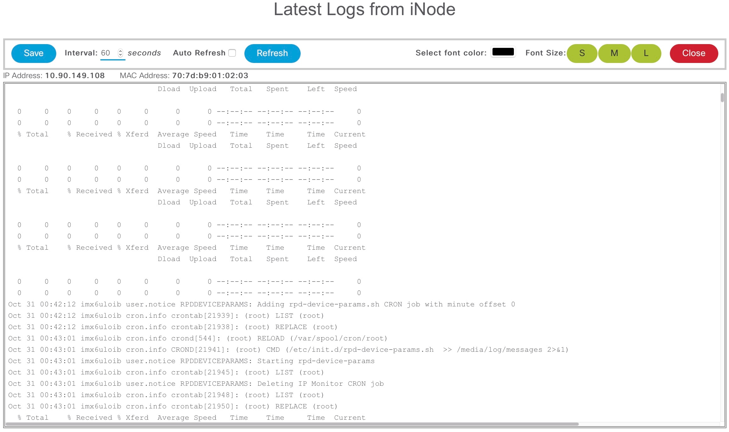
View or download the latest logs. The Latest Logs from iNode window appears. The maximum size of the file is limited to 130 KB.
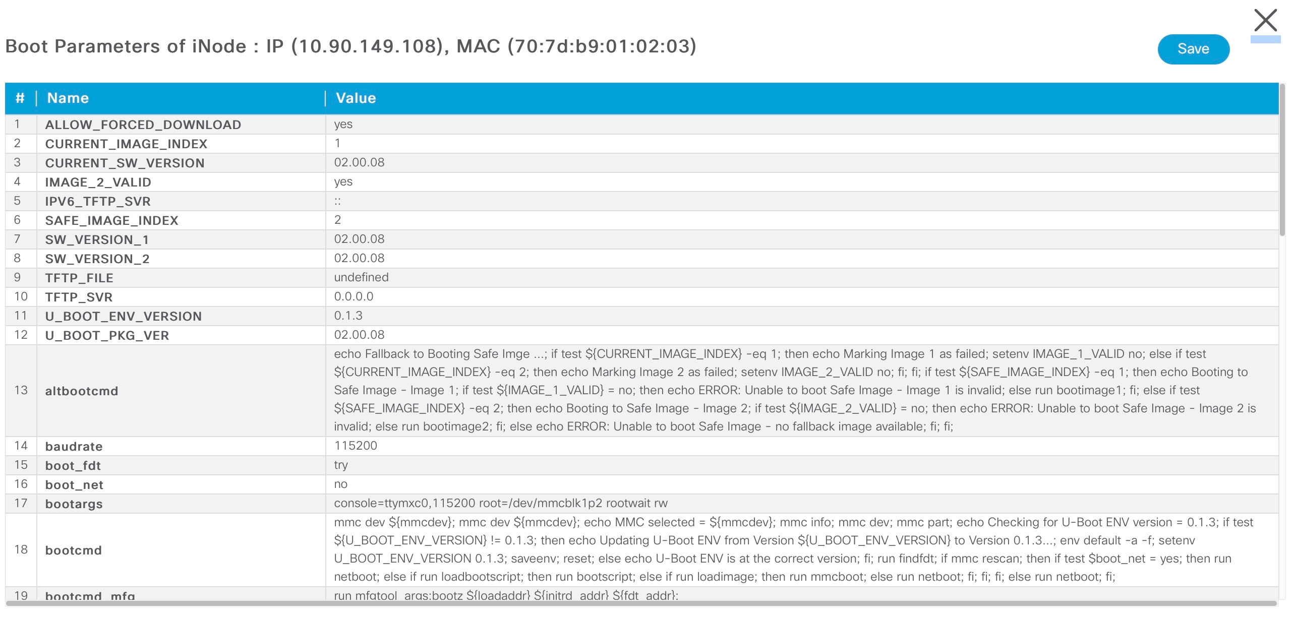
Get Boot Parameters
View and save the boot parameters.
Historical Logs
Download the entire log file. Downloading the file takes several minutes depending on the size of the log file. The progress
bar indicates the current status of the log file download.
Get Latest Logs:
Auto Refresh: Enable the Auto Refresh option in the Latest Logs from iNode window, to get the latest logs periodically. The available range of the auto refresh interval is 10–600 seconds. You can
also click the Refresh button to manually get the latest logs.
The Refresh button is disabled when you enable the Auto Refresh option.
Font color: Click the color in the Select font color option to set the color of the font. You can also set the size of the font using the Font Size options.
Click Save to download the logs to your device. The log file name is in the following format: inode-<IP address>-latest
Get Boot Parameters:
Click Save to download the boot parameters.
Historical Logs: Check the check boxes for the files that you want to download and click Download. The log file is saved to the default download location on your device. the file name is in the following format: inode-<IP address>-messages-complete
Bulk Operations on the iNodes
You can do the following bulk operations on the iNodes that are selected in the inventory:
Assign or clear the configuration profile
Initial setup
Reboot
Assign Configuration Profile
Caution
If the iNodes are already associated with a configuration profile, this operation overwrites it.
Procedure
Step 1
Log into the iNode Manager application, and click Dashboard > Launch or choose Cable iNode Manager > Overview.
Step 2
Check the check boxes for the iNodes of which you want to assign the configuration profiles.
Step 3
Click the icon.
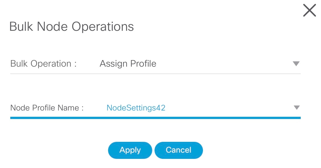
The Bulk Node Operations pop-up window appears.
Step 4
Choose the Assign Profile from the Bulk Operation drop-down list.
Step 5
Choose the profile name from the Node Profile Name drop-down list.
Clear Config Profile: If you choose None for Node Profile Name, the configuration profile is disassociated from the selected iNodes.
Step 6
Click Apply.
The node profile is assigned to the iNodes that are selected in the inventory. A warning message appears if the selected iNodes
are already associated with different profiles.
You can see the status of this bulk operation in the System > Bulk Operation Status page.
Initial Setup on iNodes
Procedure
Step 1
Log into the iNode Manager application, and click Dashboard > Launch or choose Cable iNode Manager > Overview.
Step 2
Check the check boxes of the iNodes for which you want to run the initial setup.
Step 3
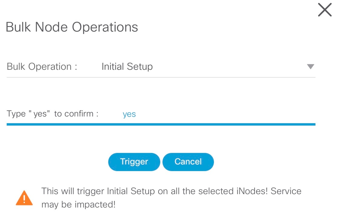
Click the icon to view the bulk operations options.
The Bulk Node Operations pop-up window appears.
Step 4
Choose Initial Setup from the Bulk Operation drop-down list.
Step 5
Enter yes in the Type "yes" to confirm field.
Step 6
Click Trigger.
You can see the status of this bulk operation in the System > Bulk Operation Status page.
Bulk Reboot of iNodes
Note
Use the bulk reboot operation cautiously. Rebooting several iNodes simultaneously may add load on the network components such
as DHCP server and TFTP server.
Procedure
Step 1
Log into the iNode Manager application, and click Dashboard > Launch or choose Cable iNode Manager > Overview.
Step 2
Check the check boxes for the iNodes of which you want to reboot the iNodes.
Note
Before triggering the reboot of iNodes, ensure that you have not checked the check box in the header of the Inventory table. Check the check box in the header of the Inventory table only if you want to reboot all iNodes in your network. It affects the services until the iNodes are rebooted and active.
Step 3
Click the icon to view the bulk operations options.
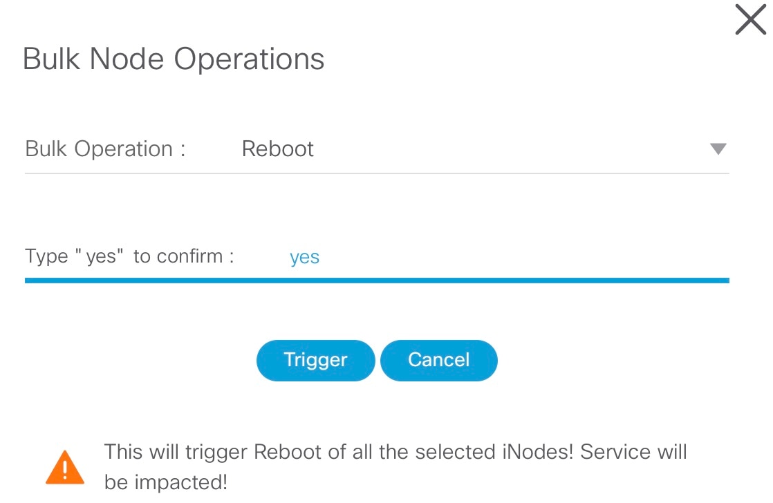
The Bulk Node Operations pop-up window appears.
Step 4
Choose Reboot from the Bulk Operation drop-down list.
Step 5
Enter yes in the Type "yes" to confirm field.
Step 6
Click Trigger.
Reboot is triggered on the iNodes that are chosen in the Inventory.
View the status of the Reboot operation in the System > Bulk Operation Status page.
Config Profiles
You can apply the same node configuration to one or more iNodes in the inventory using the options available in the Config Profiles tab. The iNode Manager application provides two configuration profile options:
RF Profiles: Contains RF port parameters such as the target frequency and amplitude, wink switch, wink attenuation (in dB, if the Wink
Switch is set as variable), and the port status.
The RF profiles are associated to a particular port in the node profile and node profiles are assigned to iNodes.
You cannot apply RF Profiles directly to the iNodes.
Node Profiles: Contains general node settings such as forward and reverse segmentation, power saving modes, OIB reverse attenuation (in
dB), and the SNMP community string. In addition, the node profile also contains the RF port settings profiles which are assigned
to the RF ports in the iNode.
You can assign a Node Profile to one or more iNodes in the inventory.
Using the Config Profiles tab, you can do the following:
Add new node and RF port configuration profiles
Update the configuration profile
Assign the node configuration profile to one or more iNodes in the inventory
Clear the association of the node configuration profiles from one or more iNodes in the inventory
View the list of configuration profiles
Delete configuration profiles
Create RF Profile
The RF Profiles tab lists the RF port settings profiles which are already created. Each RF profile panel shows whether the RF profile is
in use or not.
You can do the following with RF port profiles:
Create a new RF port profile
Edit the profile
Search for profiles
Delete the profile
Duplicate the profile
Procedure
Step 1
Log into the iNode Manager application, and click Dashboard > Launch or choose Cable iNode Manager > Config Profiles.
Step 2
Click the RF Profiles tab.
Step 3
Click the icon to create an RF port profile.
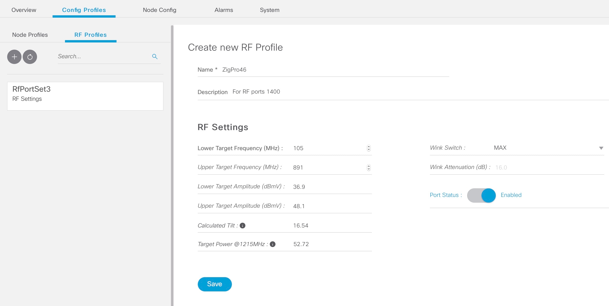
Step 4
Enter the following details in the appropriate fields.
Field
Description
Name
Name of the RF port configuration profile.
Description
Short description of the port profile.
RF Settings
Lower Target Frequency (MHz)
Lower end frequency of the RF port.
Upper Target Frequency (MHz)
Upper end frequency of the RF port.
Lower Target Amplitude (dBmV)
Lower level of output power of the RF port.
Upper Target Amplitude (dBmV)
Upper level of output power of the RF Port.
Calculated Tilt
Tilt is the difference in the signal level between the lower and upper end frequencies of the RF port. It is calculated using
the following formula:
The power level at the highest frequency of the RF port. Formula: (UpperTargetAmplitude + (tilt * (1215 - UpperTargetFrequency) / (1215 - 54)))
Wink Switch
To toggle the addition of extra attenuation.
Wink Attenuation (dB)
Reduction in the amplitude of the RF.
Port Status
Click to disable the port. By default, the port status is enabled.
Step 5
Click Save.
The new RF profile is listed on the left pane in the RF Profiles page.
Create Node Profile
The Node Profiles tab lists the node settings profiles. Each profile in the list shows the number of iNodes to which the Node Profile is assigned
to.
You can do the following with node profiles:
Create a new node profile
Edit the profile
Search for profiles
Delete the profile
Duplicate the profile
Assign the profile
Procedure
Step 1
Log into the iNode Manager application, and click Dashboard > Launch or choose Cable iNode Manager > Config Profiles.
Step 2
Click the Node Profiles tab.
Step 3
Click the icon to create a node profile.
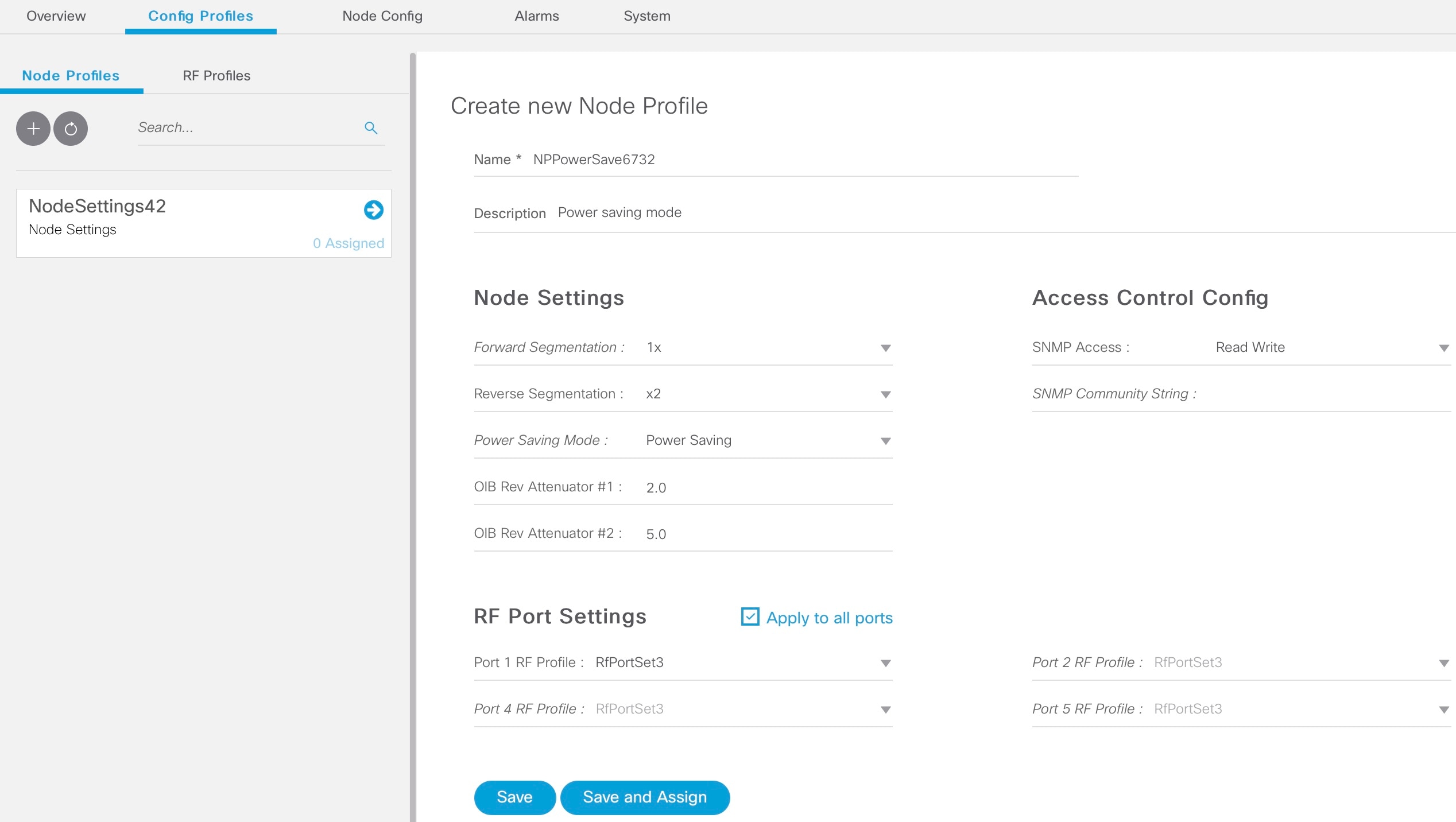
Step 4
Enter the following details in the appropriate fields.
Field
Description
Name
Name of the node configuration profile.
Description
A short description of the node profile.
Node Settings
Forward Segmentation
Number of forward paths to the headend. Intelligent Node supports only one forward path.
Reverse Segmentation
Number of reverse paths to the headend. Intelligent Node supports two reverse paths.
Power Saving Mode
Choose whether the node is in power saving mode or in full power.
OIB Rev Attenuator #1
The attenuation in the reverse transmitter #1.
OIB Rev Attenuator #2
The attenuation in the reverse transmitter #2.
Access Control Config
SNMP Access
To toggle access of the iNode through SNMP.
SNMP Community String
The community string with which the iNode parameters can be viewed and set.
RF Port Settings
Apply to all ports
Check the check box to apply the settings to all ports.
Port 1 RF Profile
Choose the RF profile from the drop-down list.
You can choose profiles for 4 ports.
Step 5
Click Save.
The new node profile is listed on the left pane in the Node Profiles page.
Assign Node Profile to iNodes
Procedure
Step 1
Log into the iNode Manager application, and click Dashboard > Launch or choose Cable iNode Manager > Config Profiles.
Step 2
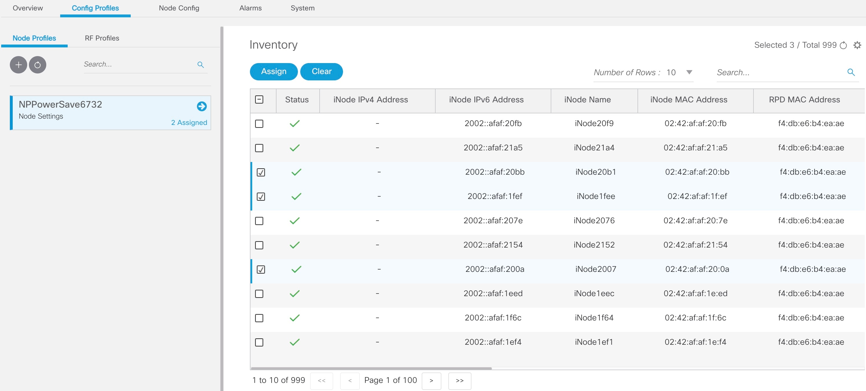
Click the Node Profiles tab and click the right arrow () next to the profile name in the left pane.
The Inventory table appears with the Assign and Clear options.
Or click the profile that you want to assign and click Assign in the Edit Node Profile page .
Step 3
Check the check boxes of the iNodes to which you want to assign the profile.
Step 4
Click Assign.
A message appears showing that assigning the profile is initiated.
View the status in the System > Bulk Operation Status page.
Node Config
The Node Config tab provides the following information:
Displays operational data of the selected iNode, along with the information on its submodule.
Allows you to configure the general settings of the iNode, and the settings of each of the RF ports of the iNode.
Allows you to query and view the forward and reverse path spectrum graphs (Amplitude (dBmV) versus frequency (MHz)) of each
of the RF ports of the selected iNode.
Displays active alarms on the iNode.
Allows you to trigger the initial setup on the iNode, and then reboot the iNode.
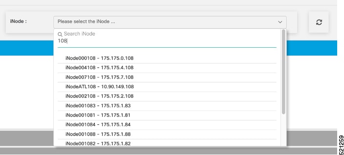
iNode Selection Box
You can use the iNode selection box to list the names and IPv4/IPv6 address of the iNode’s that are in inventory.
You can search for any substring in the name or the IP address of the iNode using the search bar. The filtered list that is
based on the search query would be displayed in the drop-down box, and you can select the iNode from the list. After you select
the iNode, the current operational data of the iNode is displayed.
Figure 1. iNode Selection Box
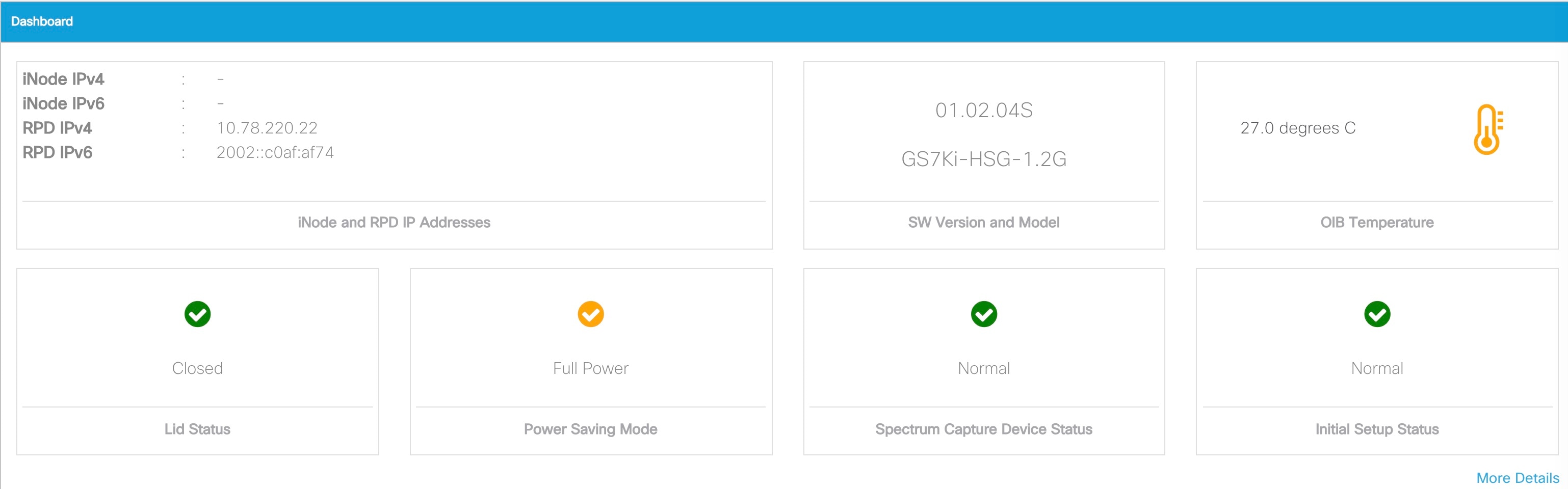
Operational Data of the Selected iNode
The operational data of the iNode is displayed in the form of scorecards. To view the operational data, complete the following
steps:
On the iNodeManager, click Node Config.
Select an iNode from the drop-down list.
Click Dashboard. The following information is displayed by default:
iNode and RPD IP addresses
Software version and model information
OIB temperature
Lid status
Spectrum capture device status
Initial setup status
To view all the operational data, click More Details. To view the default scorecards, click Show Less.
Figure 2. Dashboard Page with all Operational Data of the iNode
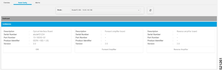
Information About Sub Modules of the iNode
The SubModules pane on the Node Config tab displays the description, serial number, part number, product identifier, and version
of the sub-modules of the iNode.
You can view the SubModules pane by completing the following step:
On the iNodeManager, click the Node Config tab.
Select the iNode for which you want to view the settings from the drop-down list.
Click SubModules. Information on the following sub-modules is displayed:
OIB
Forward Amplifier
Reverse Amplifier
Figure 3. SubModules Pane of the Node Config Tab
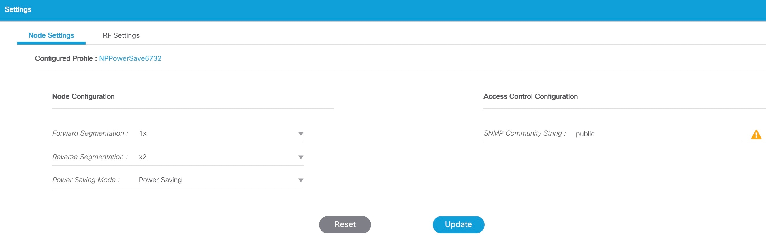
Settings
You can configure the forward segmentation, reverse segmentation, power-saving mode, and the SNMP community string on the
Settings pane. You can also view and modify the general settings of the iNode and of each of the RF ports of the iNode using
the Settings pane.
To view the Settings pane, complete the following steps:
On the iNodeManager, click the Node Config tab.
Select the iNode for which you want to view the settings from the drop-down list.
Click Settings.
Figure 4. General Settings Tab
If you have assigned a Node Setting Configuration Profile to the iNode, the profile name and profile information is displayed
when you click the profile name.
A warning icon is displayed against settings that are different in the iNode and Node Profile. Values present in the Configuration
Profile are displayed when you point to the warning icon.
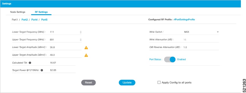
Figure 5. RF Settings Tab
You can choose to set the Lower Target Frequency and Amplitude, Upper Target Frequency and Amplitude, Wink Switch, Wink Attenuation
(in dB, if the Wink Switch is set as variable), the OIB Reverse Attenuation (in dB), and enable/disable each of the RF Port
on the Settings pane. You can also apply the settings that are configured on an RF Port to all the other ports of the iNode
by selecting the Apply Config to all ports check box.
You can calculate the value of tilt using the following formula:
You can set the RF parameters on the iNode only if the value of tilt is calculated to be 0–22 dBmV.
The target power at maximum frequency is also calculated, and the RF Port Config is allowed to be set on the iNode only if
the target power is less than 58 dBmV.
You can calculate the target power at max frequency using the following formula:
If you have assigned an RF Port Configuration Profile to the iNode, the profile name and profile information are displayed
when the profile name is clicked.
A warning icon is displayed against settings that are different in the iNode and RF Port Profile. Values present in the Configuration
Profile are displayed when you point to the warning icon.
Spectrum Graph
You can query and view the Forward Path and the Reverse Path Spectrum Graph (amplitude (in dBmV) and frequency (in MHz)) of
each of the RF Ports on the Forward and Reverse Path pane.
To view the Spectrum Graphs, complete the following steps:
On the iNodeManager, click the Node Config tab.
Select the iNode for which you want to view the settings from the drop-down list.
Click Forward and Reverse Path.
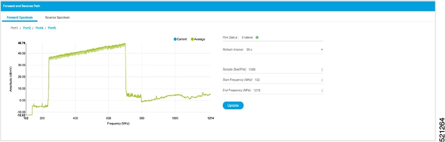
The Forward Path Spectrum Graph displays the full range of frequencies (102–1214 MHz) by default and it refreshes every 30
seconds. You can change the refresh interval, select the sample size (in KHz), the range of frequencies, and refetch the data
from the iNode. The current and the average amplitude at the frequency is displayed when you hover on the graph.
Figure 6. Forward Path Spectrum Graph
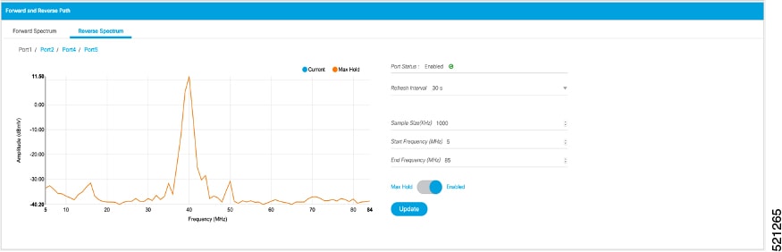
The Reverse Path Spectrum Graph displays the full range of frequencies (5–85 MHz) by default and it would refresh every 30
seconds. You can choose to change the refresh interval, select the sample size, the range of frequencies and refetch the data
from the iNode. The current and the Max Hold amplitude at the frequency is displayed when you hover on the graph.
Figure 7. Reverse Path Spectrum Graph
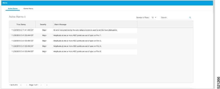
Alarms
You can view the list of active alarms, and also the history of alarms for selected iNodes by using the Alarms pane.
To view the Alarms, complete the following steps:
On the iNodeManager, click the Node Config tab.
Select the iNode for which you want to view the settings from the drop-down list.
Click Alarms.
Figure 8. Active Alarms Pane
The Alarm History table lists the timestamp at which the alarms were set and cleared on the iNode. The table lists the active
alarms as SET.
You can also choose to group the alarms based on the category, and then select each category to view the timestamps.
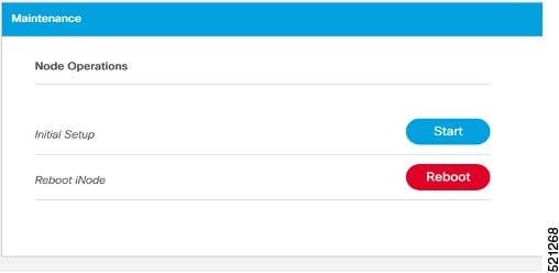
Maintenance
The Maintenance pane allows you to trigger the initial setup operation in the selected iNode, and allows you to reboot the
selected iNode.
To view the Maintenance pane, complete the following steps:
On the iNodeManager, click the Node Config tab.
Choose the iNode for which you want to view the settings from the drop-down list.
Click Maintenance.
Figure 9. Maintenance Pane
Initial Setup
When initial-setup is triggered, the output level of the input source is measured and the attenuators on the OIB are adjusted
to optimize the input level into the forward amplifier. After successful completion, the Initial Setup Status on the Dashboard turns green (status: Normal)
Note
Before you click the Start button for the Initial Setup, set the port frequencies and levels, enable at least Port 1, and save the configuration on the RF configuration pages.
Perform the Initial Setup in the following scenarios:
Replacing RPD or iNode
Changing the RF band, especially when modifying high and low frequencies
Modifying the power level from CCAP core
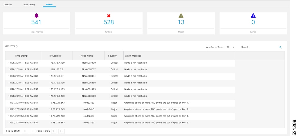
Alarms
You can use the Alarms tab to list the total number of active alarms in the iNode’s, along with the number of alarms based
on their severity in a table. You can select the number of rows to be displayed on page and can filter the alarms that are
displayed by specifying a substring using the search. You can also filter the alarms based on severity by clicking the corresponding
scorecard.
To view the Alarms, complete the following steps:
On the iNodeManager, click the Alarms tab.
Figure 10. Alarms Tab
System
You can choose to take backup of the database, import a database file into the iNode Manager, and to view the results of the
bulk operations using the System tab.
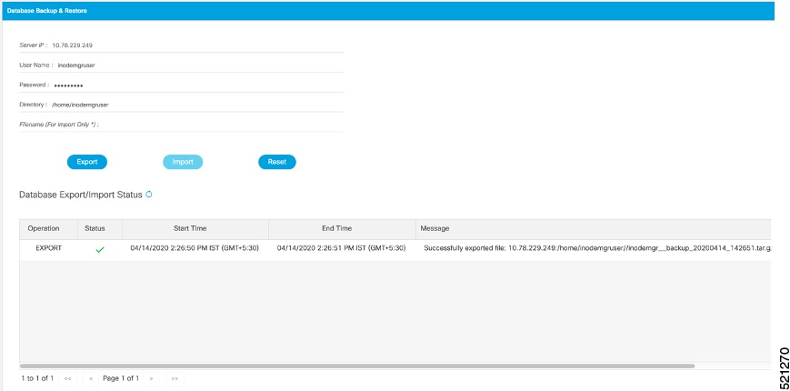
Database Backup and Restore
You can create a backup of the database, and also restore the iNode Manager to an earlier state by importing a database file
by using the Database Backup and Restore pane. You can also view the results and status of the backup and restore operations
that were performed earlier.
To view the Database Backup and Restore pane, complete the following steps:
On the iNodeManager, click the System tab.
Click Database Backup and Restore.
Figure 11. Database Backup and Restore Pane
Note
The Database Import operation is possible only if the iNode Manager does not have any data. Ensure that the iNode Manager
does not have any iNode and configuration profiles.
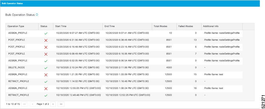
Bulk Operation Status
You can view the status of the bulk operations using the Bulk Operation Status pane.
To view the Bulk Operation Status, complete the following steps:
On the iNodeManager, click the System tab.
Click the Bulk Operation Status pane.
Figure 12. Bulk Operation Status
For Bulk Configuration Profile operations such as Post Profile and Assign Profile, the configuration profile name is listed in Additional Info. The table displays the status of the last 15 bulk operations carried out. The status of the operation on each iNode can
be viewed by clicking the corresponding record on the table.
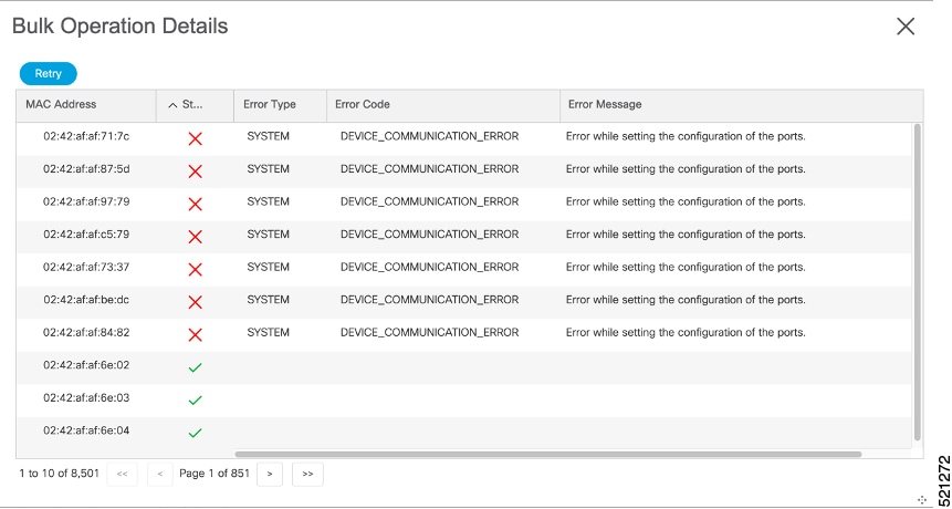
Figure 13. Bulk Operation Details
Click Retry to reattempt the bulk operation on the failed iNodes. The corresponding records related to the bulk operation would be updated
with the retry status.
For bulk operations that might be In Progress for a long time, you can choose to click the Abort button.
Inventory Dashboard
The Inventory dashboard provides you utilities to add, organize, and update information about the network devices. The Inventory
dashboard also allows you to create credential profiles that applies credential settings consistently across devices.
Inventory
You can use the Inventory tab to add, organize, and update information about the network devices. This includes non cable devices too, and hence the
information to be provided is more exhaustive than in the iNode Manager’s view of the inventory.
A new iNode can be added in the inventory table or via the iNode Manager Dashboard.
Table 1. Descriptions of the Inventory Table
Name
Description
Status
Shows a graphical pie chart of all devices in the network, which is categorized by status:
Online
Offline
Type
Shows a graphical pie chart of the type of devices in the network
Manufacturer
Shows a graphical pie chart of manufacturer of the devices in the network
Status
Current Status of the device
Hostname
Hostname of the device
Key Type
MAC ADDRESS / IP ADDRESS
IP Address
IP Address of the device
MAC Address
MAC Address of the device
UUID
Universally Unique Identifier of the device
Product Type
Product Type of the device
Credential Profile
Credential Profile Name
Latitude
Latitude of the device
Longitude
Longitude of the device
Location
Location of the device
Description
Description of the device
Software Version
Software Version of the device
Model Number
Model Number of the device
Adds a device to existing inventory.
Deletes a device from inventory.
Exports device information to a CSV file.
Imports devices by using a CSV file.
Details
Displays a dialog box with the history of the connectivity status of the selected device.
Sets the columns in the device table.
Search
Allows you to search for and filter the network devices.
Credential Profiles
Credential profiles are collections of device credentials for SNMP, and Telnet/SSH to network devices. Using credential profiles
allows you to apply credential settings consistently across devices. When you add or import devices, you can specify the credential
profile that the devices should use. If you must make credential changes, such as changing a device password, you can edit
the profile to update the settings across all devices that use that profile.
Note
The Credential Profile is not applicable for iNode’s.
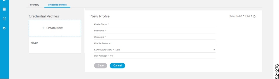
To create a Credential Profile, complete the following steps:
On the iNodeManager, click Inventory > Credential Profiles.
Click Create New.
Provide a profile name, username and other credentials for the profile.
We recommend that you provide the profile with a detailed description, as it will be displayed on the Credential Profiles
panel. Note that when a device is added or updated using this profile, the content you specify here is applied to the device.
Click Save.
Figure 14. Creating a New Credential Profile
Table 2. Descriptions of the Credential Profiles Form
Name
Description
Create New
Allows you to add or edit a credential profile.
Note: Mandatory fields are marked with an asterisk.
Profile Name
Name of the profile
Username
Username of the device
Password
Password of the device
Connectivity Type
Choose to use either an SSH or a Telnet connection type


 Feedback