
Technical Specifications
|
Parameters |
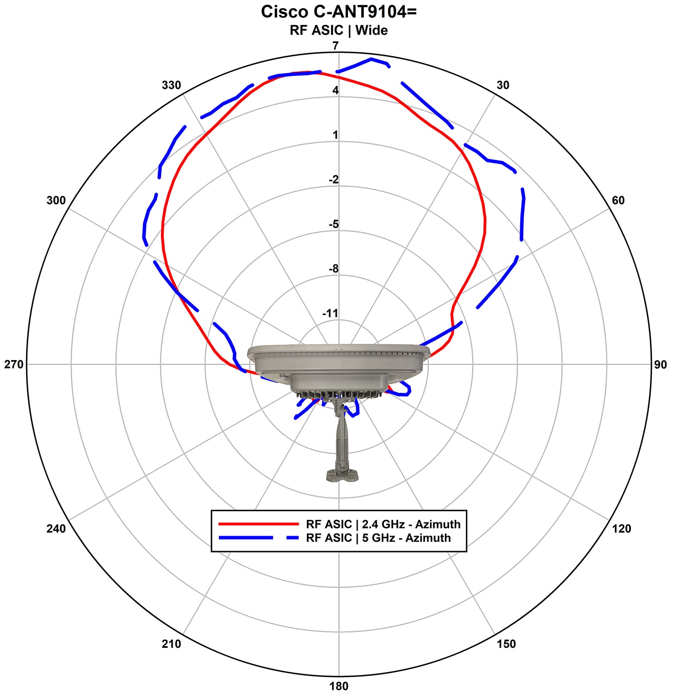
2.4-GHz |
5-GHz Wide Beamwidth |
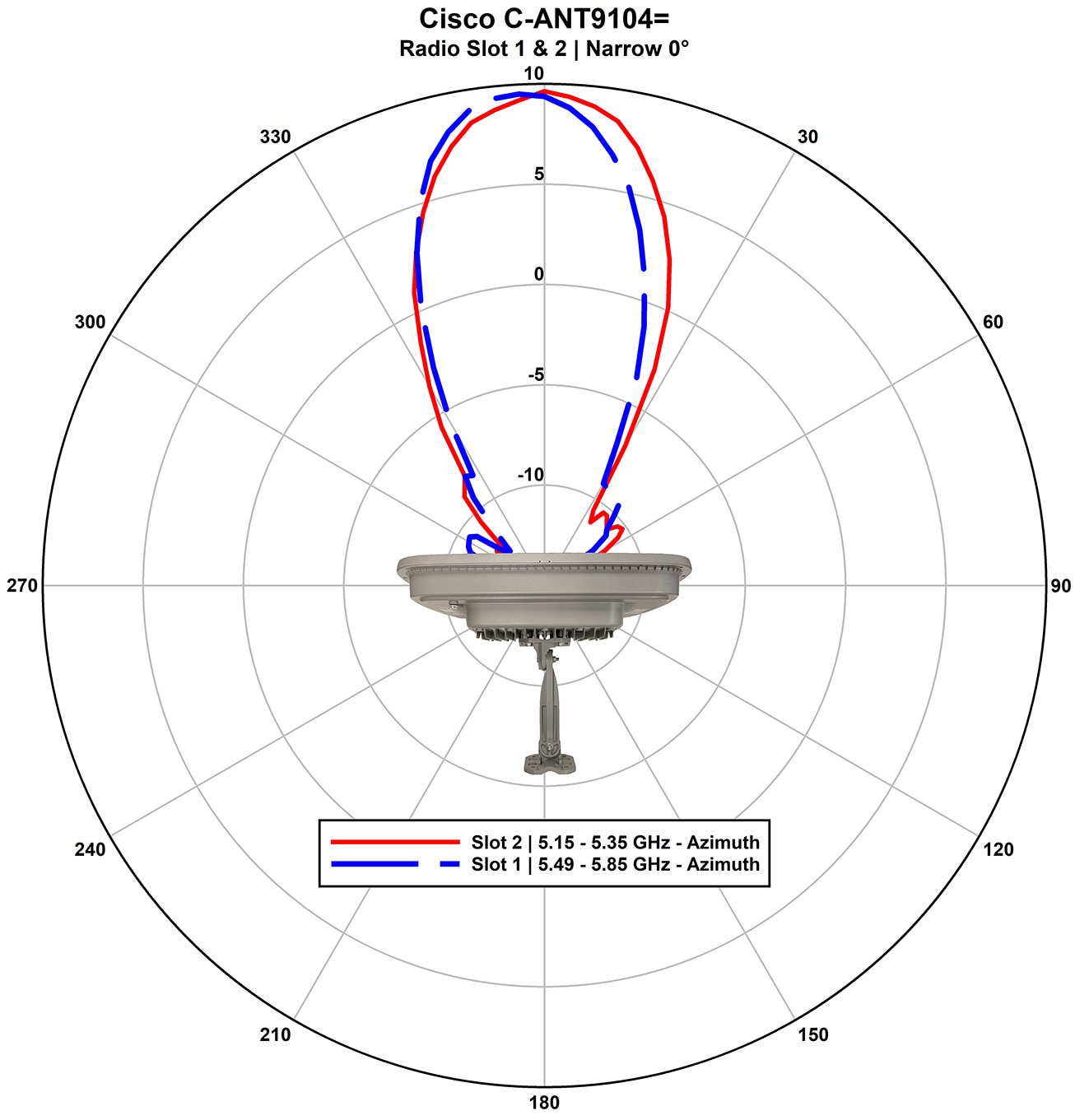
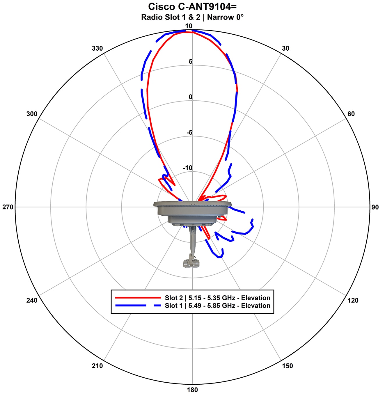
5-GHz Narrow Beamwidth Boresight |
5-GHz Narrow Beamwidth 10° |
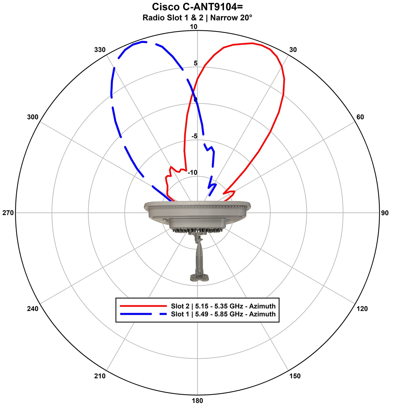
5-GHz Narrow Beamwidth 20° |
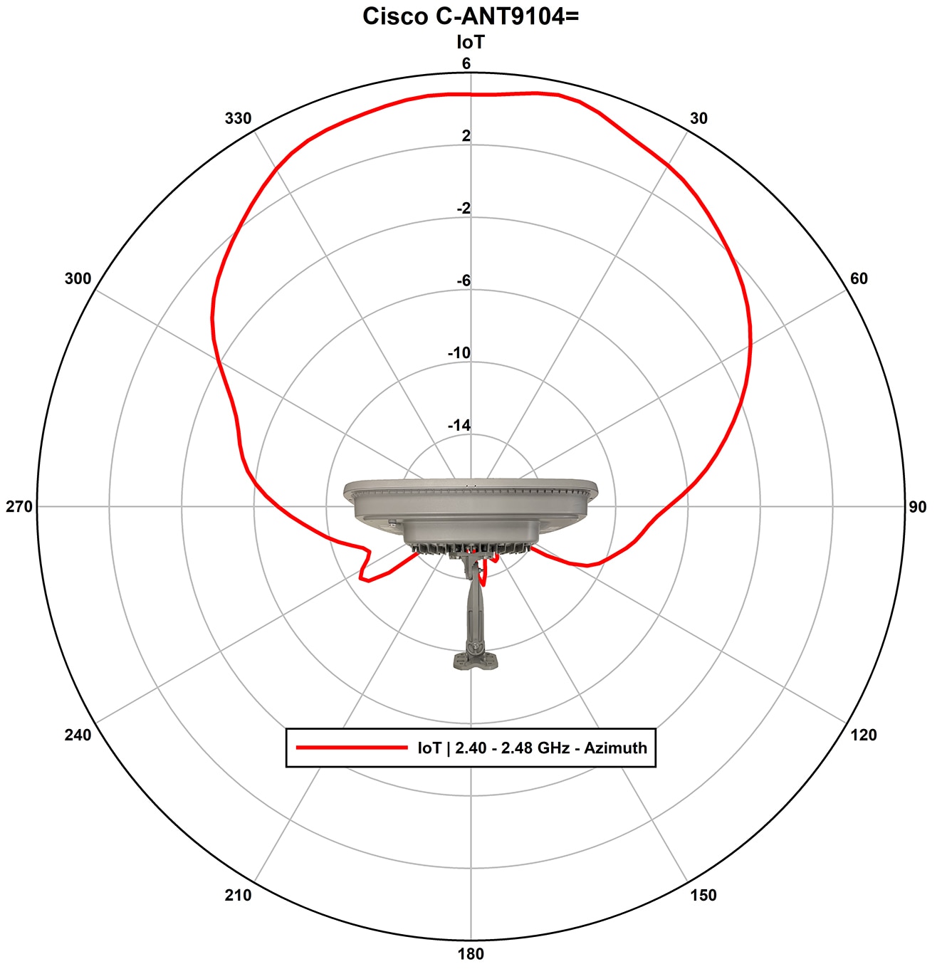
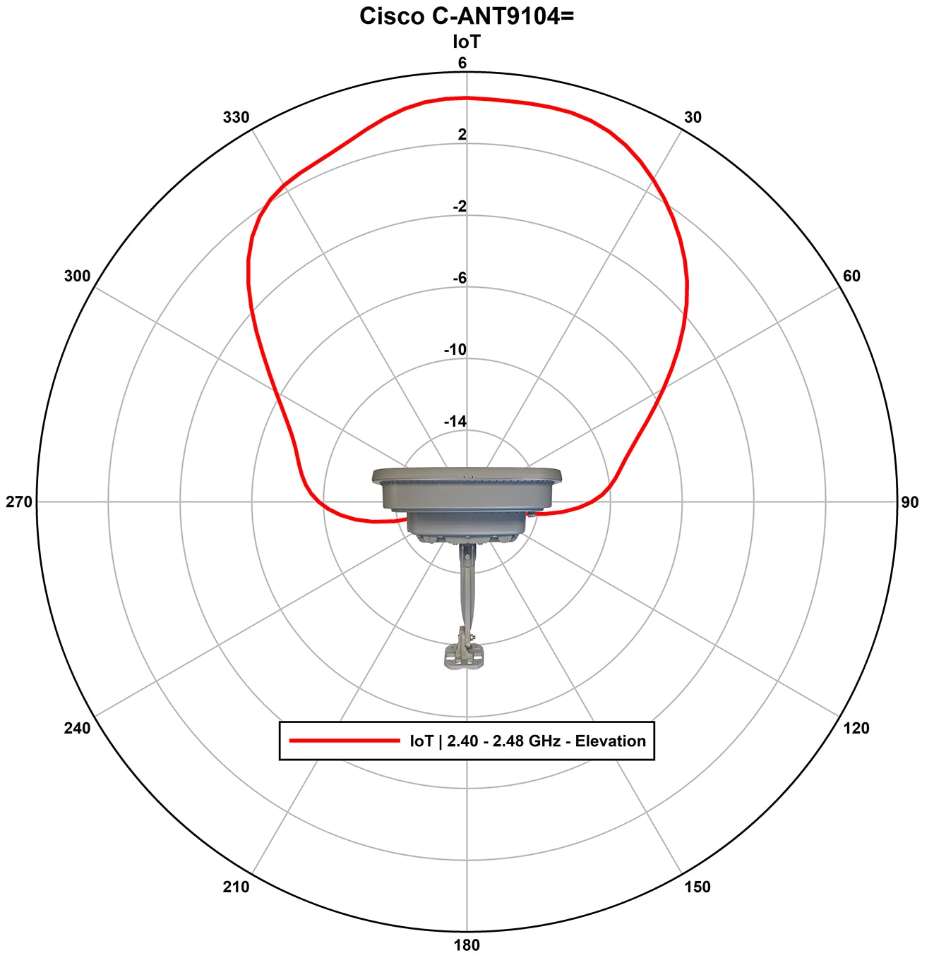
IoT |
|---|---|---|---|---|---|---|
|
Nominal Input Impedance |
50 Ohms |
50 Ohms |
50 Ohms |
50 Ohms |
50 Ohms |
50 Ohms |
|
Voltage Standing Wave Ratio (VSWR) |
2:1 |
2:1 |
2:1 |
2:1 |
2:1 |
2:1 |
|
Peak Gain |
6 dBi |
7 dBi |
10 dBi |
10 dBi |
10 dBi |
6 dBi |
|
Polarization |
Ports A and C are vertically polarized |
Ports A, C, E, and G are vertically polarized |
Ports A, C, E, and G are vertically polarized |
Ports A, C, E, and G are vertically polarized |
Ports A, C, E, and G are vertically polarized |
Vertically Polarized |
|
Ports B and D are horizontally polarized |
Ports B, D, F, and H are horizontally polarized |
Ports B, D, F, and H are horizontally polarized |
Ports B, D, F, and H are horizontally polarized |
Ports B, D, F, and H are horizontally polarized |
||
|
3–dB Beamwidth Azimuth |
70° |
80° |
25° |
25° |
25° |
70° |
|
3–dB Beamwidth Elevation |
70° |
25° |
25° |
25° |
25° |
70° |
|
Sidelobe Level |
NA |
-21 dBr |
-30 dBr |
-30 dBr |
-30 dBr |
NA |
|
Front-to-Back Ratio |
-15 dBr |
-20 dBr |
-30 dBr |
-30 dBr |
-30 dBr |
-15 dBr |
|
Connector Type |
RJ45 PoE |
|||||
|
Width |
23.5 in. (59.70 cm) |
|||||
|
Height |
18.2 in. (46.23 cm) |
|||||
|
Depth |
5.8 in. (14.8 cm) |
|||||
|
Weight |
15.5 lbs (7.03 Kg) |
|||||
|
Water/Foreign Body Ingress |
IP65 |
|||||
|
Operational Wind |
100 mph |
|||||
|
Operating Temperature Range |
No solar loading: -20°C to 60°C (-4°F to 140°F) With solar loading and solar cover: up to 50°C (122°F) |
|||||
|
Storage Temperature Range |
-40°C to 70°C (-40°F to 158°F) |
|||||


 Feedback