How to Use Cisco iNode Manager

This section describes how to use the Cisco iNode Manager application:

Logging into Cisco iNode Manager Application

Access the Cisco iNode Manager Web UI using the following URL:

  • With FQDN disabled:
    https://<ingress-ip>.nip.io
    • For all-in-one (AIO) cluster, the ingress IP address is the management IP address of the ops node or VM.

    • For multi node, the ingress IP address is the virtual IP address that is configured for the management network.

  • With FQDN enabled:
    https://<ingress-hostname>

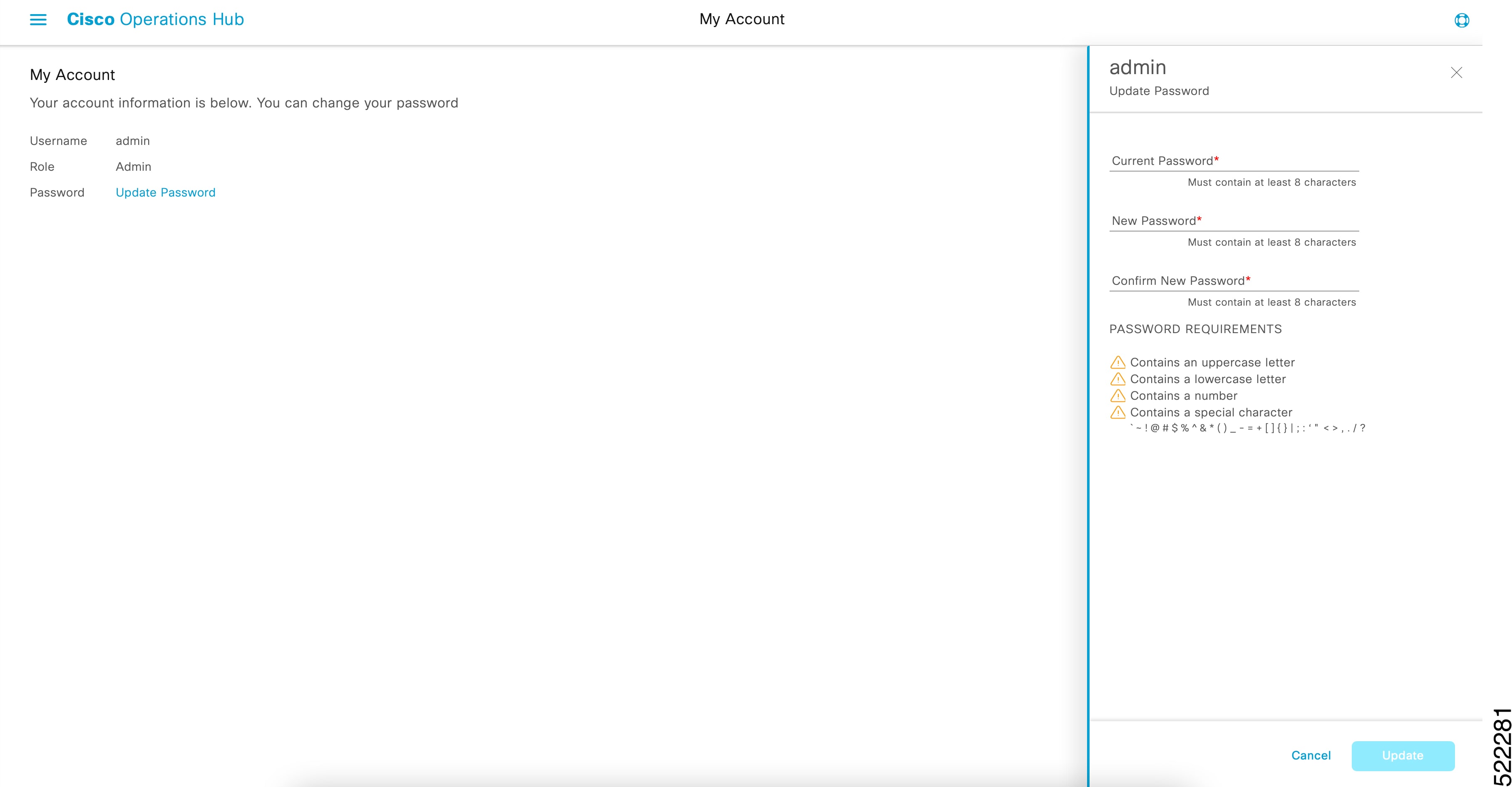
You can log into the Cisco iNode Manager application by entering the credentials that are provided for inode manager operations center while installing the Cisco iNode Manager. Currently, admin is the only user profile that is allowed.

Enter the password that you mentioned while creating the Cisco iNode Manager cluster.

The LDAP user credentials can be entered if LDAP is configured in the Cisco iNode Manager cluster. For information on how to configure LDAP authentication in the Cisco iNode Manager, see the Cisco iNode Manager Installation Guide.


Note


The login page is locked for one minute if there are three consecutive unsuccessful attempts to log into the iNode Manager.
Figure 1. Operations Hub Welcome Page

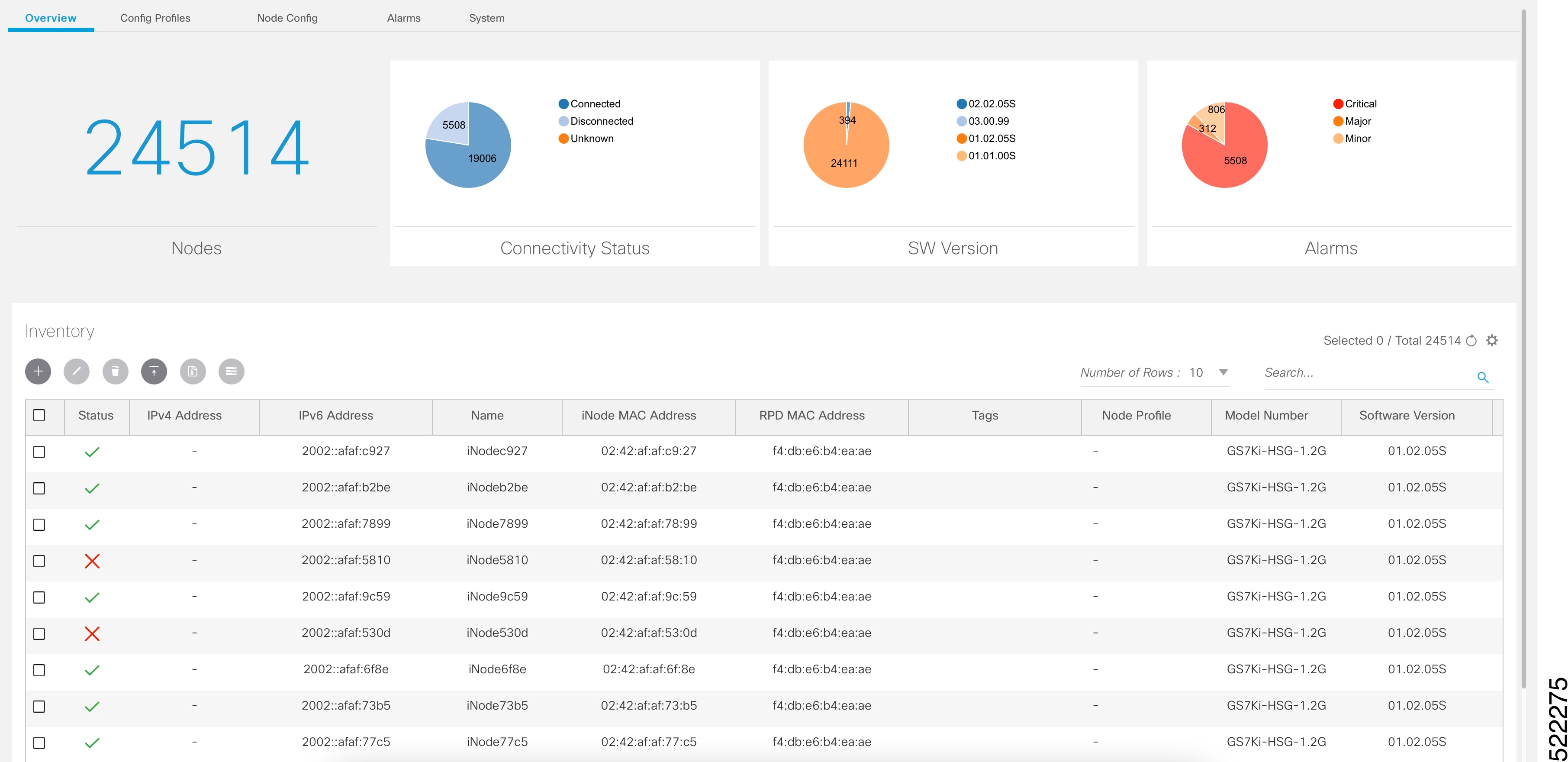
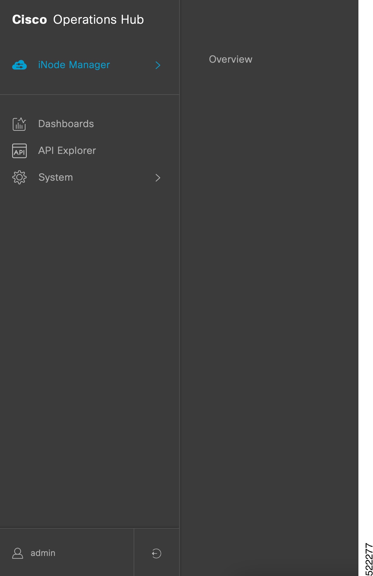
Launch the iNode Manager application by clicking the hamburger button on the top left corner of the Welcome Page and choose iNode Manager > Overview.


Note


To logout from the iNode Manager application, click the hamburger button and select Log out at the bottom of the Operation Hubs Hamburger Menu.

Cisco iNode Manager Application

The Cisco iNode Manager application page provides you options to add, organize, and update information about the iNodes in the network.

The iNode Manager page has five tabs:

  • Overview

  • Config Profiles

  • Node Config

  • Alarms

  • System

Overview

The Overview page provides the total number of iNodes, their connectivity status, software version running on them, and the number of active alarms. It also has an Inventory table which shows details of all iNodes in the network. You can perform the following tasks on this page:

  • Add a new iNode to the inventory

  • Update the name of the iNode in the inventory

  • Delete iNodes from the inventory

  • Export the iNode details from the inventory table in the CSV format

  • Download log files that are in the iNode, view the latest logs, and the boot parameters of an iNode

  • Perform bulk operations: Initial setup in bulk, assign configuration profiles, assign tag, and bulk reboot

The following table contains the descriptions of the graphs on the Overview page and the fields in the inventory table:

Name

Description

Nodes

Total number of iNodes in the inventory.

Connectivity Status

Shows a pie chart of the connectivity status of the iNodes in the network. The following statuses are displayed:

  • Connected

  • Disconnected

  • Unknown

SW Version

Shows a pie chart of the number of iNodes running different software versions.

Alarms

Shows a pie chart of the number of active alarms in the iNodes in the network. The following categories are displayed:

  • Critical

  • Major

  • Minor

Note


The muted alarms are not counted in total alarms. Refer to Alarm Settings for more information.

Inventory Table Fields

Status

Current Status of the iNode.

iNode IPv4 Address

IPv4 address of the iNode.

A hyphen (-) indicates that the iNode does not have an IPv4 address.

iNode IPv6 Address

IPv6 Address of the iNode.

A hyphen (-) indicates that the iNode does not have an IPv6 Address.

iNode Name

Name of the iNode.

iNode MAC Address

MAC address of the iNode.

RPD MAC Address

MAC address of the RPD that is connected to the iNode.

Node Profile

Name of the Configuration Profile that is assigned to the iNode.

Model Number

Model number of the iNode.

Software Version

Software version of the iNode.

Safe Image Version

Software version of the secondary image in the iNode.

Serial Number

Serial number of the iNode.

RPD IPv4 Address

IPv4 address of the RPD that is connected to the iNode.

RPD IPv6 Address

IPv6 address of the RPD that is connected to the iNode.

RPD Serial Number

Serial number of the RPD that is connected to the iNode.

RPD Software Version

Software version of the RPD that is connected to the iNode.

Hamburger button. Opens the hamburger menu.

Adds an iNode to the inventory.

Updates the iNode information.

Deletes iNodes from the inventory.

Exports iNode details to a CSV file.

Downloads the iNode’s logs.

Perform bulk operations.

Sets the columns in the inventory table.

Search

Allows you to search for iNodes based on the search criteria.

Add an iNode to Inventory

Procedure

Step 1

Log into the Cisco iNode Manager application, click the hamburger button and choose iNode Manager > Overview.

Step 2

Click the icon to add a node to the Inventory.

The Add iNode pop-up window appears.

Step 3

Enter the IPv4 address or the IPv6 address of the iNode.

The Cisco iNode Manager retrieves the rest of the details of the iNode, such as the name, MAC address, software version, serial number, and so on, from the iNode and stores it in the inventory.

Step 4

(Optional) Assign one or more tags to the iNode.

You can create a new tag by typing the name of the tag in the corresponding text box and clicking the Enter key. Or you can select the tags that were already created from the drop-down box.

Note


It is not recommended to create one new tag per iNode. The main purpose of the tag is to group iNode. So that it is easier to filter and view the iNode in the inventory table and perform bulk operations.

Step 5

Click Save to add the node.


Update the iNode Name

You can only update the name of an iNode.

Procedure

Step 1

Log into the Cisco iNode Manager application, click the hamburger button and choose iNode Manager > Overview.

Step 2

In the Inventory table, check the check box of the iNode which you want to update.

Step 3

Click the icon to update the name of the iNode.

The Update iNode pop-up window appears.

Step 4

Update the node name.

Step 5

(Optional) Associate tags to the iNode, or remove tags from the iNode.

Step 6

Click Save.


Delete iNode from Inventory

You can delete multiple iNodes from the Inventory.

Procedure

Step 1

Log into the Cisco iNode Manager application, click the hamburger button and choose iNode Manager > Overview.

Step 2

Select the iNodes from the Inventory table and click the icon.

A confirmation message appears.

Step 3

Click Delete to confirm.


Export the Inventory

You can export the details of all iNodes listed in the Inventory in the CSV format.

Procedure

Step 1

Log into the iNode Manager application, click the hamburger button and choose iNode Manager > Overview.

Step 2

In the Inventory table, check the check boxes for the iNodes of which you want the details exported in a CSV file.

Step 3

Click the icon to export iNodes in the inventory.

A request message to allow downloads appears. This request appears only once for a user profile.

Step 4

Click Allow.

The CSV file is saved to your downloads location on your device. The file name is in the following format: inodeInventoryData-yyyy-mm-dd.hhmmss


Download Logs

You can view and download the logs to your device.

Procedure

Step 1

Log into the iNode Manager application, click the hamburger button and choose iNode Manager > Overview.

Step 2

Check the check boxes for the iNodes of which you want to download the logs.

Step 3

Click the icon to view the download options.

The Download Logs pop-up window appears.

Step 4

Click the option based on your requirement.

Option Description
Get Latest Logs View or download the latest logs. The Latest Logs from iNode window appears. The maximum size of the file is limited to 130 KB.

Get Boot Parameters

View and save the boot parameters.

Historical Logs

Download the entire log file. Downloading the file takes several minutes depending on the size of the log file. The progress bar indicates the current status of the log file download.

Get Latest Logs:

  • Auto Refresh: Enable the Auto Refresh option in the Latest Logs from iNode window, to get the latest logs periodically. The available range of the auto refresh interval is 10–600 seconds. You can also click the Refresh button to manually get the latest logs.

    The Refresh button is disabled when you enable the Auto Refresh option.

  • Font color: Click the color in the Select font color option to set the color of the font. You can also set the size of the font using the Font Size options.

Click Save to download the logs to your device. The log file name is in the following format: inode-<IP address>-latest

Get Boot Parameters:

Click Save to download the boot parameters.

Historical Logs: Check the check boxes for the files that you want to download and click Download. The log file is saved to the default download location on your device. the file name is in the following format: inode-<IP address>-messages-complete


Bulk Operations on the iNodes

You can do the following bulk operations on the iNodes that are selected in the inventory:

  • Assign or clear the configuration profile

  • Initial setup

  • Reboot

  • Associate or diassociate tags

Assign Configuration Profile

Caution


If the iNodes are already associated with a configuration profile, this operation overwrites it.


Procedure

Step 1

Log into the iNode Manager application, click the hamburger button and choose iNode Manager > Overview.

Step 2

Check the check boxes for the iNodes of which you want to assign the configuration profiles.

Step 3

Click the icon.

The Bulk Node Operations pop-up window appears.

Step 4

Choose the Assign Profile from the Bulk Operation drop-down list.

Step 5

Choose the profile name from the Node Profile Name drop-down list.

Clear Config Profile: If you choose None for Node Profile Name, the configuration profile is disassociated from the selected iNodes.

Step 6

Click Apply.

The node profile is assigned to the iNodes that are selected in the inventory. A warning message appears if the selected iNodes are already associated with different profiles.

You can see the status of this bulk operation in the System > Bulk Operation Status page.


Initial Setup on iNodes
Procedure

Step 1

Log into the iNode Manager application, click the hamburger button and choose iNode Manager > Overview.

Step 2

Check the check boxes of the iNodes for which you want to run the initial setup.

Step 3

Click the icon to view the bulk operations options.

The Bulk Node Operations pop-up window appears.

Step 4

Choose Initial Setup from the Bulk Operation drop-down list.

Step 5

Enter yes in the Type "yes" to confirm field.

Step 6

Click Trigger.

You can see the status of this bulk operation in the System > Bulk Operation Status page.


Bulk Reboot of iNodes

Note


Use the bulk reboot operation cautiously. Rebooting several iNodes simultaneously may add load on the network components such as DHCP server and TFTP server.


Procedure

Step 1

Log into the iNode Manager application, click the hamburger button and choose iNode Manager > Overview.

Step 2

Check the check boxes for the iNodes of which you want to reboot the iNodes.

Note


Before triggering the reboot of iNodes, ensure that you have not checked the check box in the header of the Inventory table. Check the check box in the header of the Inventory table only if you want to reboot all iNodes in your network. It affects the services until the iNodes are rebooted and active.

Step 3

Click the icon to view the bulk operations options.

The Bulk Node Operations pop-up window appears.

Step 4

Choose Reboot from the Bulk Operation drop-down list.

Step 5

Enter yes in the Type "yes" to confirm field.

Step 6

Click Trigger.

Reboot is triggered on the iNodes that are chosen in the Inventory.

View the status of the Reboot operation in the System > Bulk Operation Status page.


Associate and Diassociate the Tags
Procedure

Step 1

Log into the iNode Manager application, click the hamburger button and choose iNode Manager > Overview.

Step 2

Check the check boxes for the iNodes of which you want to associate or diassociate tags.

Step 3

Click the icon.

The Bulk Node Operations pop-up window appears.

Step 4

Choose the Tags from the Bulk Operation drop-down list.

Step 5

To associate or diassociate the tags on the selected iNode, choose the tags from the drop-down list, then click the Update Tags button. You can also create new tag by specifying the name of the tag in the corresponding text field and click the Enter key.

Step 6

To remove all the tags associated with the selected iNode, click the Remove Tags button.

The Remove Tags button is disabled if you choose any tags in Step 5.

Note


You can manage the tags in the System > Tag Management page.


Config Profiles

You can apply the same node configuration to one or more iNodes in the inventory using the options available in the Config Profiles tab. The iNode Manager application provides two configuration profile options:

  • RF Profiles: Contains RF port parameters such as the target frequency and amplitude, wink switch, wink attenuation (in dB, if the Wink Switch is set as variable), and the port status.

    The RF profiles are associated to a particular port in the node profile and node profiles are assigned to iNodes.

    You cannot apply RF Profiles directly to the iNodes.

  • Node Profiles: Contains general node settings such as forward and reverse segmentation, power saving modes, OIB reverse attenuation (in dB), and the SNMP community string. In addition, the node profile also contains the RF port settings profiles which are assigned to the RF ports in the iNode.

    You can assign a Node Profile to one or more iNodes in the inventory.

Using the Config Profiles tab, you can do the following:

  • Add new node and RF port configuration profiles

  • Update the configuration profile

  • Assign the node configuration profile to one or more iNodes in the inventory

  • Clear the association of the node configuration profiles from one or more iNodes in the inventory

  • View the list of configuration profiles

  • Delete configuration profiles

Create Node Profile

The Node Profiles tab lists the node settings profiles. Each profile in the list shows the number of iNodes to which the Node Profile is assigned to.

You can do the following with node profiles:

  • Create a new node profile

  • Edit the profile

  • Search for profiles

  • Delete the profile

  • Duplicate the profile

  • Assign the profile

Procedure

Step 1

Log into the iNode Manager application, click the hamburger button and choose iNode Manager > Overview.

Step 2

Select Config Profiles tab from the top of the screen.

Step 3

Select the Node Profiles tab.

Step 4

Click the icon to create a node profile.

Step 5

Enter the following details in the appropriate fields.

Field

Description

Name

Name of the node configuration profile.

Description

A short description of the node profile.

Node Settings

Forward Segmentation

Number of forward paths to the headend. Intelligent Node supports only one forward path.

Reverse Segmentation

Number of reverse paths to the headend. Intelligent Node supports two reverse paths.

Power Saving Mode

Choose whether the node is in power saving mode or in full power.

OIB Rev Attenuator #1

The attenuation in the reverse transmitter #1.

OIB Rev Attenuator #2

The attenuation in the reverse transmitter #2.

Access Control Config

SNMP Access

To toggle access of the iNode through SNMP.

SNMP Community String

The community string with which the iNode parameters can be viewed and set.

RF Port Settings

Apply to all ports

Check the check box to apply the settings to all ports.

Port 1 RF Profile

Choose the RF profile from the drop-down list.

You can choose profiles for 4 ports.

Step 6

Click Save.

The new node profile is listed on the left pane in the Node Profiles page.


Create RF Profile

The RF Profiles tab lists the RF port settings profiles which are already created. Each RF profile panel shows whether the RF profile is in use or not.

You can do the following with RF port profiles:

  • Create a new RF port profile

  • Edit the profile

  • Search for profiles

  • Delete the profile

  • Duplicate the profile

Procedure

Step 1

Log into the iNode Manager application, click the hamburger button and choose iNode Manager > Overview.

Step 2

Select Config Profiles tab from the top of the screen.

Step 3

Select the RF Profiles tab.

Step 4

Click the icon to create an RF port profile.

Step 5

Enter the following details in the appropriate fields.

Field

Description

Name

Name of the RF port configuration profile.

Description

Short description of the port profile.

RF Settings

Lower Target Center Frequency (MHz)

Lower end frequency of the RF port.

Upper Target Center Frequency (MHz)

Upper end frequency of the RF port.

Lower Target Amplitude (dBmV)

Lower level of output power of the RF port.

Upper Target Amplitude (dBmV)

Upper level of output power of the RF Port.

Calculated Tilt

Tilt is the difference in the signal level between the lower and upper end frequencies of the RF port. It is calculated using the following formula:
((UpperTargetAmplitude -
        LowerTargetAmplitude) * ((1215 - 54)) / (UpperTargetFrequency -
        LowerTargetFrequency)))

Target Power @1215MHz

The power level at the highest frequency of the RF port. Formula: (UpperTargetAmplitude + (tilt * (1215 - UpperTargetFrequency) / (1215 - 54)))

Wink Switch

To toggle the addition of extra attenuation.

Wink Attenuation (dB)

Reduction in the amplitude of the RF.

Port Status

Click to disable the port. By default, the port status is enabled.

Step 6

Click Save.

The new RF profile is listed on the left pane in the RF Profiles page.


Assign Node Profile to iNodes

Procedure

Step 1

Log into the iNode Manager application, click the hamburger button and choose iNode Manager > Overview.

Step 2

Select Config Profiles tab from the top of the screen.

Step 3

Select the Node Profiles tab and click the right arrow () next to the profile name in the left pane.

The Inventory table appears with the Assign and Clear options.

Or click the profile that you want to assign and click Assign in the Edit Node Profile page .

Step 4

Check the check boxes of the iNodes to which you want to assign the profile.

Step 5

Click Assign.

A message appears showing that assigning the profile is initiated.

View the status in the System > Bulk Operation Status page.


Node Config

The Node Config tab provides the following information:

  • Displays operational data of the selected iNode, along with the information on its submodule.

  • Allows you to configure the general settings of the iNode, and the settings of each of the RF ports of the iNode.

  • Allows you to query and view the forward and reverse path spectrum graphs (Amplitude (dBmV) versus frequency (MHz)) of each of the RF ports of the selected iNode.

  • Displays active alarms on the iNode.

  • Allows you to trigger the initial setup on the iNode, and then reboot the iNode.

iNode Selection Box

You can use the iNode selection box to list the names and IPv4/IPv6 address of the iNode’s that are in inventory.

You can search for any substring in the name or the IP address of the iNode using the search bar. The filtered list that is based on the search query would be displayed in the drop-down box, and you can select the iNode from the list. After you select the iNode, the current operational data of the iNode is displayed.

Figure 2. iNode Selection Box


Operational Data of the Selected iNode

The operational data of the iNode is displayed in the form of scorecards. To view the operational data, complete the following steps:

  1. On the iNodeManager, click Node Config.

  2. Select an iNode from the drop-down list.

  3. Click Dashboard. The following information is displayed by default:

    • iNode and RPD IP addresses

    • Software version and model information

    • OIB temperature

    • Lid status

    • Spectrum capture device status

    • Initial setup status

    • Power saving mode

To view all the operational data, click More Details. To view the default scorecards, click Show Less.

Figure 3. Dashboard Page with all Operational Data of the iNode


Information About Sub Modules of the iNode

The SubModules pane on the Node Config tab displays the description, serial number, part number, product identifier, and version of the sub-modules of the iNode.

You can view the SubModules pane by completing the following step:

  1. On the iNodeManager, click the Node Config tab.

  2. Select the iNode for which you want to view the settings from the drop-down list.

  3. Click SubModules. Information on the following sub-modules is displayed:

    • OIB

    • Forward Amplifier

    • Reverse Amplifier

Figure 4. SubModules Pane of the Node Config Tab


Settings

You can configure the forward segmentation, reverse segmentation, power-saving mode, and the SNMP community string on the Settings pane. You can also view and modify the general settings of the iNode and of each of the RF ports of the iNode using the Settings pane.

To view the Settings pane, complete the following steps:

  1. On the iNodeManager, click the Node Config tab.

  2. Select the iNode for which you want to view the settings from the drop-down list.

  3. Click Settings.

Figure 5. General Settings Tab


If you have assigned a Node Setting Configuration Profile to the iNode, the profile name and profile information is displayed when you click the profile name.

A warning icon is displayed against settings that are different in the iNode and Node Profile. Values present in the Configuration Profile are displayed when you point to the warning icon.

Figure 6. RF Settings Tab


You can choose to set the Lower Target Center Frequency and Amplitude, Upper Target Center Frequency and Amplitude, Wink Switch, Wink Attenuation (in dB, if the Wink Switch is set as variable), the OIB Reverse Attenuation (in dB), and enable/disable each of the RF Port on the Settings pane. You can also apply the settings that are configured on an RF Port to all the other ports of the iNode by selecting the Apply Config to all ports check box.

You can calculate the value of tilt using the following formula:

((UpperTargetAmplitude - LowerTargetAmplitude) * ((1215 - 54)) / 
(UpperTargetFrequency - LowerTargetFrequency)))

Note


You can set the RF parameters on the iNode only if the value of tilt is calculated to be 0–22 dBmV.


The target power at maximum frequency is also calculated, and the RF Port Config is allowed to be set on the iNode only if the target power is less than 58 dBmV.

You can calculate the target power at max frequency using the following formula:
(UpperTargetAmplitude + (tilt * (1215 - UpperTargetFrequency) / (1215 - 54)))

If you have assigned an RF Port Configuration Profile to the iNode, the profile name and profile information are displayed when the profile name is clicked.

A warning icon is displayed against settings that are different in the iNode and RF Port Profile. Values present in the Configuration Profile are displayed when you point to the warning icon.

Spectrum Graph

You can query and view the Forward Path and the Reverse Path Spectrum Graph (amplitude (in dBmV) and frequency (in MHz)) of each of the RF Ports on the Forward and Reverse Path pane.

To view the Spectrum Graphs, complete the following steps:

  1. On the iNode Manager, click the Node Config tab.

  2. Select the iNode for which you want to view the settings from the drop-down list.

  3. Click Forward and Reverse Path.

    The Forward Path Spectrum Graph displays the full range of frequencies (102–1214 MHz) by default and it refreshes every 30 seconds. You can change the refresh interval, select the sample size (in KHz), the range of frequencies, and refetch the data from the iNode. The current and the average amplitude at the frequency is displayed when you hover on the graph.

    The table in the right part displays user-configured amplitude and actual level of the amplitude at the lower target and the upper target frequencies.

Figure 7. Forward Path Spectrum Graph

The Reverse Path Spectrum Graph displays the full range of frequencies (5–85 MHz) by default and it would refresh every 30 seconds. You can choose to change the refresh interval, select the sample size, the range of frequencies and refetch the data from the iNode. The current and the Max Hold amplitude at the frequency is displayed when you hover on the graph.

Figure 8. Reverse Path Spectrum Graph


Alarms

You can view the list of active alarms, and also the history of alarms for the selected iNode by using the Alarms pane.

To view the Alarms, complete the following steps:

  1. On the iNodeManager, click the Node Config tab.

  2. Select the iNode for which you want to view the settings from the drop-down list.

  3. Click Alarms.

Figure 9. Active Alarms Pane


The Muted column indicates whether the alarm is muted by the user.

You can export the list of active alarms as a CSV file by clicking the Export CSV button.

The Alarms History table lists the timestamp at which the alarms were set and cleared on the iNode. The table lists the active alarms as SET.

Figure 10. Alarms History Pane


You can also choose to group the alarms based on the category, and then select each category to view the timestamps.

You can also export the alarm history as a CSV file by clicking the Export CSV button.

Maintenance

The Maintenance pane allows you to trigger the initial setup operation in the selected iNode, and allows you to reboot the selected iNode.

To view the Maintenance pane, complete the following steps:

  1. On the iNodeManager, click the Node Config tab.

  2. Choose the iNode for which you want to view the settings from the drop-down list.

  3. Click Maintenance.

Figure 11. Maintenance Pane


Initial Setup

When initial-setup is triggered, the output level of the input source is measured and the attenuators on the OIB are adjusted to optimize the input level into the forward amplifier. After successful completion, the Initial Setup Status on the Dashboard turns green (status: Normal)


Note


Before you click the Start button for the Initial Setup, set the port frequencies and levels, enable at least Port 1, and save the configuration on the RF configuration pages.


Perform the Initial Setup in the following scenarios:

  • Replacing RPD or iNode

  • Changing the RF band, especially when modifying high and low frequencies

  • Modifying the power level from CCAP core

Alarms

You can use the Alarms tab to list the total number of unmuted alarms in the iNode’s, along with the number of unmuted alarms based on their severity in a table. You can select the number of rows to be displayed on page and can filter the alarms that are displayed by specifying a substring using the search. You can also filter the alarms based on severity by clicking the corresponding scorecard.

To view the Alarms, complete the following step:

  1. On the iNodeManager, click the Alarms tab.

To view the muted alarms, click the Muted Alarms scorecard.

Figure 12. Alarms Tab


Alarm Settings

In Alarm Settings section, all alarm categories are enabled by default. You can uncheck the box corresponding to the alarm category to mute that category of alarms. The muted alarms are not displayed in the Alarms table, and they are not counted as part of the alarm statistics.

All Power Supply related alarms can be muted by checking the corresponding PS (Power Supply) checkbox at the bottom of the section. After making the change, click the Enable button to update the Alarm Settings.

Figure 13. Alarm Settings

System

You can choose to take backup of the database, import a database file into the iNode Manager, and to view the results of the bulk operations using the System tab.

Database Backup and Restore

You can create a backup of the database, and also restore the iNode Manager to an earlier state by importing a database file by using the Database Backup and Restore pane. You can also view the results and status of the backup and restore operations that were performed earlier.

To view the Database Backup and Restore pane, complete the following steps:

  1. On the iNodeManager, click the System tab.

  2. Click Database Backup and Restore.

Figure 14. Database Backup and Restore Pane


Note


The Database Import operation is possible only if the iNode Manager does not have any data. Ensure that the iNode Manager does not have any iNode, configuration profile, and the DB export schedule.


Database Import Validation

Starting from Cisco iNode Manager release 3.2.0, the exported database file contains important metadata and the checksum. The checksum is used to validate the database file during the import operation. The metadata in the database file is displayed to the user during the import operation. The user can confirm/cancel the database import operation after checking the metadata.

Figure 15. Database Import Confirmation

If you try to import a database file that was exported from the iNode Manager prior to release 3.2.0, you can see the following warning message and confirm/cancel the database import.

If the database file is found to be corrupt while importing, the database import will stop and you will see the following message.

Database Export Scheduling

You can schedule the database export at the following intervals:

  • every 1 to 6 days

  • every week

  • every month

Figure 16. Database Export Scheduling

Only one schedule can be configured. To delete the schedule, click on the Delete button.

Bulk Operation Status

You can view the status of the bulk operations using the Bulk Operation Status pane.

To view the Bulk Operation Status, complete the following steps:

  1. On the iNodeManager, click the System tab.

  2. Click the Bulk Operation Status pane.

Figure 17. Bulk Operation Status


For Bulk Configuration Profile operations such as Post Profile and Assign Profile, the configuration profile name is listed in Additional Info. The table displays the status of the last 15 bulk operations carried out. The status of the operation on each iNode can be viewed by clicking the corresponding record on the table.

Figure 18. Bulk Operation Details


Click Retry to reattempt the bulk operation on the failed iNodes. The corresponding records related to the bulk operation would be updated with the retry status.

For bulk operations that might be In Progress for a long time, you can choose to click the Abort button.

Tag Management

Tag Management pane displays the information about the tags that were created by the user. Tag Management Status table lists the name of the tag, the number of iNode to which the tag is associated with, the name of the user who created the tag, and the time at which the tag was created.

Figure 19. Tag Management

You can create a new tag by clicking the button. The tags that are not associated with any iNode can be removed by selecting the tags in the table, and then clicking the button.

Operations Hub Metrics Dashboard

To open the Grafana Metrics Dashboard, click the hamburger button and choose Dashboards.

Figure 20. Operations Hub Metrics Dashboard

This page displays the various statistics that are available both from the iNode Manager application and the underlying Kubenetes and infra.

The following are a few snapshots of the statistics that are provided by the iNode Manager application:

Figure 21. Operations Hub Metrics – iNode Manager Application – Spring Boot – Basic Stats
Figure 22. Operations Hub Metrics – iNode Manager Application – Spring Boot – HTTP Stats

The following are a few snapshots of the statistics that are exposed by Kubernetes, and the infra pods:

Figure 23. Operations Hub Metrics – Node CPU, Memory and Disk Usage
Figure 24. Operations Hub Metrics – Cassandra Stats
Figure 25. Operations Hub Metrics – Elastic Search Stats

Using REST APIs

API Explorer

To open the API Explorer Dashboard:

  1. Click the hamburger button and select API Explorer.

  2. Click iNode Service Manager under INODE MANAGER API to open the iNode Service Manager API Docs page.

The iNode Service Manager API Docs can also be launched directly by using the URL:

  • With FQDN disabled:
    https://<ingress-ip>.nip.io/home/inodemanager/api-explorer/inode-service-manager
    • For all-in-one (AIO) cluster, the ingress IP address is the management IP address of the ops node or VM.

    • For multi node, the ingress IP address is the virtual IP address that is configured for the management network.

  • With FQDN enabled:
    https://<ingress-hostname>/home/inodemanager/api-explorer/inode-service-manager
Figure 26. API Explorer – iNode Service Manager API Docs

API Authentication

Use the following steps to add Authentication token in Operations Hub

  1. Create a base64 encoded string of an Ops Hub user’s username and password. For example:

    echo -n 'admin:lab' | base64
    YWRtaW46bGFi

    In this example the user name is admin and password is lab.

  2. Collect an access_token by submitting the base64 encoded string using basic authentication to API: /api/auth/v1/token.

    curl -X POST https://<cluster-mgmt-IP-address>/api/auth/v1/token -H  "accept: application/json" -H "authorization: Basic YWRtaW46bGFi" -k
     
    Response code: 201
    Response body
     
    {
    "access_token": "eyJhbGciOiJIUzI1NiIsInR5cCI6IkpXVCJ9.eyJ1c2VybmFtZSI6ImFkbWluIiwicm9sZSI6ImxpLWF
    kbWlufGFwaS12aWV3ZXJ8YXBpLWVkaXRvcnxhcGktYWRtaW4iLCJzYWx0IjoiZU9ZR0RtRFBsVFVwaEg1WCIsImV4cCI6MTY4
    MTc3Nzg2NCwic3ViIjoiYWRtaW4ifQ.gYIFghIusN4uN6ok0Ey8sANPTqRw_VcWmvtqklzkNDU",
    "refresh_token": "uWjDc2TzPSvIzOWveMlQfHT5-V6DnzzMcdiatGi5",
    "refresh_token_expire": 1684348264,
    "token_type": "jwt"
    } 

    Note


    The access_token is valid for 12 hours. It can be refreshed by submitting both the access_token and refresh_token to API: /api/auth/v1/token/fresh. For more information, access API Explorer > Authentication, at the main menu in Operations Hub.


  3. Use the access_token collected in Step 2 to make subsequent REST API calls.

    curl -X GET https://<cluster-mgmt-IP-address>/api/rbac/v1/identitymgmt/user -H  "accept: 
    application/json" -H "Authorization: Bearer eyJhbGciOiJIUzI1NiIsInR5cCI6IkpXVCJ9.eyJ1c2VybmFtZSI6ImFkbWluIi
    wicm9sZSI6ImxpLWFkbWlufGFwaS12aWV3ZXJ8YXBpLWVkaXRvcnxhcGktYWRtaW4iLCJzYWx0IjoiZU9ZR0RtRFBsVFVwaEg1WCIsImV4c
    CI6MTY4MTc3Nzg2NCwic3ViIjoiYWRtaW4ifQ.gYIFghIusN4uN6ok0Ey8sANPTqRw_VcWmvtqklzkNDU" -k
     
    Response code: 201
    Response body
     
    {
    "userDetailList": [
      {
       "groupList": [
        "admin",
        "api-admin",
        "api-editor",
        "api-viewer",
        "li-admin"
       ],
       "username": "admin",
       "passwordExpiryPeriod": "325"
      }
    ]
    }
  4. Before the access_token expires, refresh the token by submitting both the access_token and refresh_token to API: /api/auth/v1/token/fresh. For more information, access API Explorer > Authentication, at the main menu in Operations Hub.

Update the Admin Password

The admin user can update the password by clicking on the admin username at the bottom of the Operation Hubs Hamburger Menu.

Figure 27. Operations Hub Hamburger Menu

Update the password in the Update Password pane of the My Account page. Make sure to follow the password requirements in the pane.

Figure 28. Update Password

A message displays when the password expires in less than 30 days. You can change the password by clicking the Reset your password link.

Figure 29. Password Expiry Reminder

Renewing the Cisco iNode Manager Certification

Cisco iNode Manager utilizes an X.509 certificate to secure the communications channel between it and the Cisco GS7000 Intelligent Nodes it manages. The certificate validity period is 11 months from the date the iNode Manager software was installed. if the certificate expires, you lose the ability to remotely manage your GS7000 Intelligent Nodes. In iNodeManager 24.1 an the certificate is automatically renewed after 300 days ( approximately 10 months) while for all the previous releases the certificate is automatically renewed after 270 days. The validity of certificate is 11 from the date of renewal. User can also renew the certificate manually as follows.

AIO

For AIO, login to the cluster and use the following steps to restart the inode-service-manager pod:

Procedure


Step 1

Identify the inode-service-manager.

Example:

inodemgruser@cicd-aio-229-control-plane:~$ kubectl get pods -A | grep inode-manager-data
inode-manager-data   diskutil-9ltzz                                                1/1     Running     2          26d
inode-manager-data   documentation-79cf864479-w22dp                                1/1     Running     2          26d
inode-manager-data   inode-registry-service-8495f69bdb-wvfp6                       1/1     Running     4          23d
inode-manager-data   inode-service-manager-b7bdcf769-k7lpd                         1/1     Running     3          26d
inode-manager-data   inodemanager-grafana-dashboard-metrics-7754fc5589-vstnv       1/1     Running     2          26d
inode-manager-data   ops-center-inode-manager-data-ops-center-7b64855f7c-dk82g     5/5     Running     10         26d
inode-manager-data   robot-ui-74b86b4979-txgwr                                     2/2     Running     4          26d
inode-manager-data   smart-agent-inode-manager-data-ops-center-b9867c68-8c7rv      1/1     Running     5          26d

Step 2

Delete the inode-service-manager.

Example:

inodemgruser@cicd-aio-229-control-plane:~$ kubectl delete pod -name  inode-service-manager-b7bdcf769-k7lpd -n inode-manager-data
pod "inode-service-manager-b7bdcf769-k7lpd" deleted
The inode-service-manager restarts automatically.

Step 3

Ensure that inode-service-manager pod restarts with a different ID appended at the end.

Example:

inodemgruser@cicd-aio-229-control-plane:~$ kubectl get pods -A | grep inode-manager-data
inode-manager-data   diskutil-9ltzz                                                1/1     Running     2          26d
inode-manager-data   documentation-79cf864479-w22dp                                1/1     Running     2          26d
inode-manager-data   inode-registry-service-8495f69bdb-wvfp6                       1/1     Running     4          23d
inode-manager-data   inode-service-manager-b7bdcf769-rhlxk                         1/1     Running     0          46s
inode-manager-data   inodemanager-grafana-dashboard-metrics-7754fc5589-vstnv       1/1     Running     2          26d
inode-manager-data   ops-center-inode-manager-data-ops-center-7b64855f7c-dk82g     5/5     Running     10         26d
inode-manager-data   robot-ui-74b86b4979-txgwr                                     2/2     Running     4          26d
inode-manager-data   smart-agent-inode-manager-data-ops-center-b9867c68-8c7rv      1/1     Running     5          26d

Multinode Setup

For Multinode setup, login into the control plane and execute the kubectl get pods command.

Procedure


Step 1

Example:

inodemgruser@cicd-multi-node-211-control-plane-1:~$ kubectl get pods -A | grep inode-manager-data
inode-manager-data   diskutil-8jwst                                                1/1     Running     2          25d
inode-manager-data   diskutil-gcdhm                                                1/1     Running     2          25d
inode-manager-data   diskutil-ldvxn                                                1/1     Running     2          25d
inode-manager-data   documentation-556f96574-pn6lx                                 1/1     Running     1          11d
inode-manager-data   inode-registry-service-74bddb657f-khtnz                       1/1     Running     2          25d
inode-manager-data   inode-registry-service-74bddb657f-smr4g                       1/1     Running     1          11d
inode-manager-data   inode-registry-service-74bddb657f-vhrpt                       1/1     Running     2          25d
inode-manager-data   inode-service-manager-6b5f8694b4-jf5kz                        1/1     Running     0          9d
inode-manager-data   inode-service-manager-6b5f8694b4-kmj66                        1/1     Running     0          9d
inode-manager-data   inode-service-manager-6b5f8694b4-vs2p7                        1/1     Running     0          9d
inode-manager-data   inodemanager-grafana-dashboard-metrics-b794f6ccf-5b7h7        1/1     Running     2          25d
inode-manager-data   ops-center-inode-manager-data-ops-center-69ff64db6-vg7xl      5/5     Running     0          9d
inode-manager-data   robot-ui-7bd88c77cb-jckxd                                     2/2     Running     2          11d
inode-manager-data   smart-agent-inode-manager-data-ops-center-557c6cc9b8-55t7h    1/1     Running     6          25d
It shows three ISM pods running in three VMs.

Step 2

Delete the three ISM pods and ensure that ISM pods restart as mentioned in the preceding AIO setup.